download the package with used files and compilers from here: https://media.henriaanstoot.nl/assembly.tgz
extract with tar xzvf /tmp/assembly.tgz to a directory
start dosbox and mount the directory as C
mount c /path/assembly
Run “a line”, this a batchfile which starts the editor (qedit) When closing the file (esc – q menu) It will compile the assembly and write out a executable
This is the batchfile
@echo off
q %1.asm
cls
masm %1.asm;
link %1.obj;
exe2bin %1.exe %1.com
echo READY!
line assemblycode
    NAME lijnentrekroutine

.286

Code SEGMENT
    ASSUME CS:Code,DS:Code
org 100h
Start:
    mov ax,13h            ;set video mode
    int 10h

    mov bx,100
    mov cx,100
hiero:
    mov dx,0a000h
    mov es,dx
    mov ax,320
    mul cx
    add ax,bx
    mov di,ax
    mov al,2
    stosb
    inc bx
    inc bx
    inc cx
    cmp bx,150
    jnz hiero


    mov ah,8
    int 21h
    mov ax,3
    int 10h

    MOV AX,4C00h
    INT 21h

code ends
end start
While playing with MuseScore…. (Typesetting some scores for Pipes and Flute)
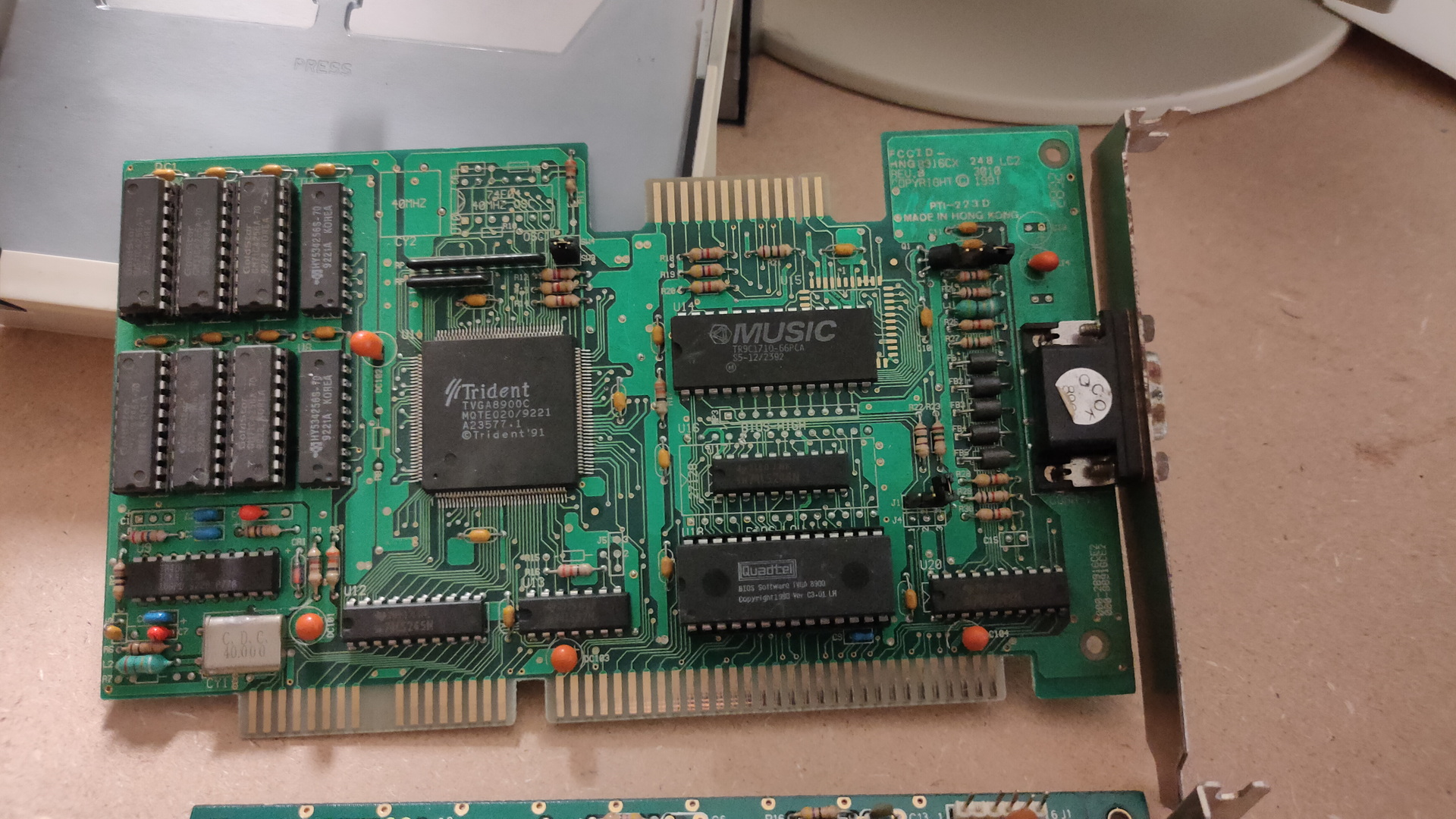
This came in: WOOOT
Trident 8900C (1024 x768 max 512Kb)
This is a Trident VGA card. While having a 16bit ISA connector, it can work in a 8bits ISA slot.
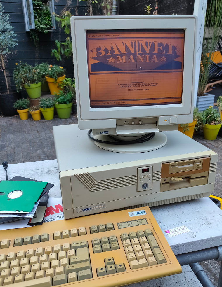
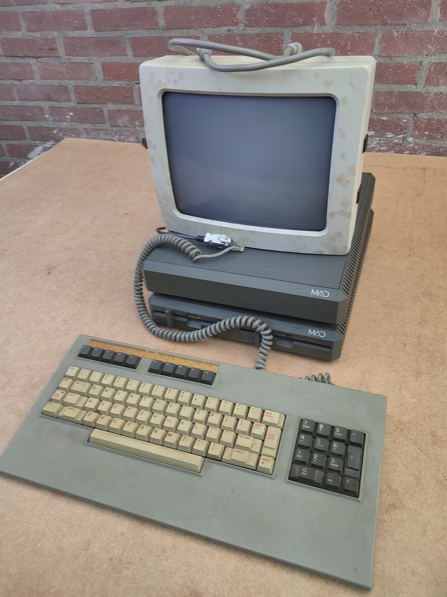
A while ago i bought a Laser XT/3, that’s the one my parents had. This is where i did a lot of assembly programming on. It’s a 8086 cpu, 640K and has a Hercules/CGA graphics card.
I found loads of assembly files and i want to see if i can get it running again. While some code was written for hercules, ( That’s the monochrome image you see in the example above ) and a few for EGA (4 colors).
Most of it was written for VGA. Probably on a later machine like a 80386?
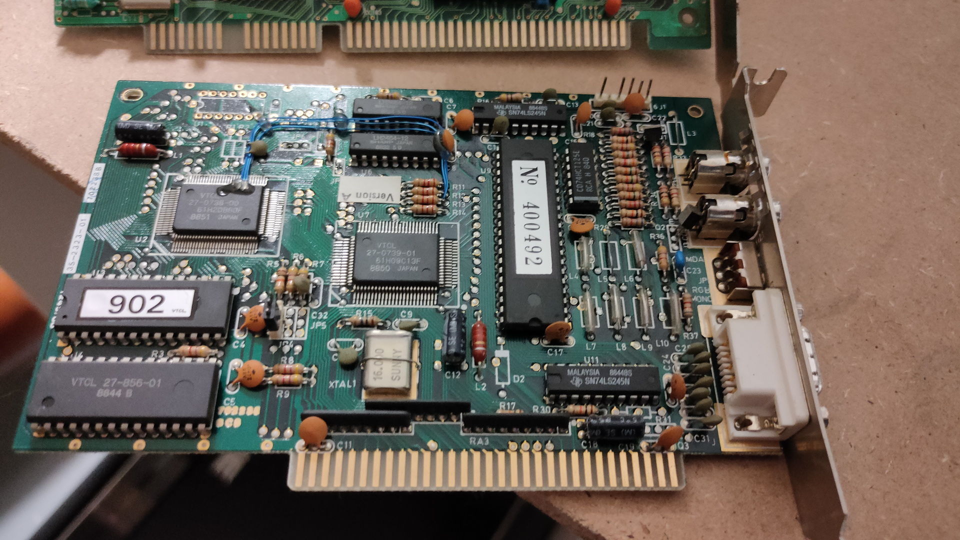
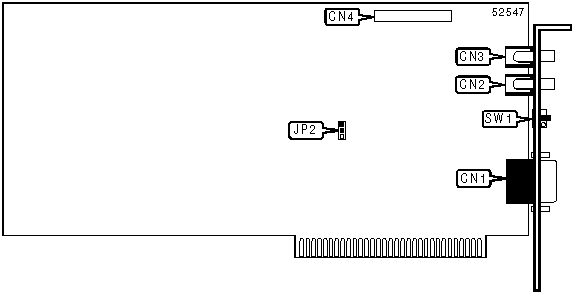
But i know there are vga cards for 8 bit msdos computers, and i found one. ( This one is even autodetect, so no jumpers to figure out)
So i’ve put this card in the machine, turned it on, and it works! I’ve got only 2 examples living on the harddisk of the machine, both black and white … 🙂 I have to search for interesting code in hundreds of files.
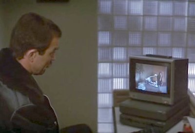
Some friends of mine, picture was taken from an amiga genlock digitizerThe intro pages of a “amiga emulator” WHERE is the rest??? (end is a cga starfield demo)
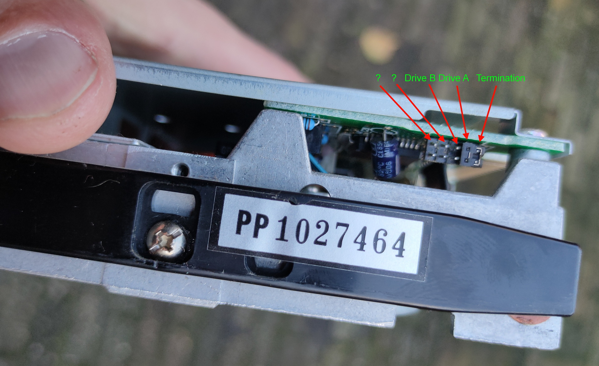
And a boot demo, which was able to start from a bootsector, went into a graphic mode and ran a demo with sound. Edk wrote a sector loader for this. I have some 5.25 inch floppy disks, labelled boot demo. So i wanted to try this today … I needed to change the boot order, so i went online to search for jumper settings.
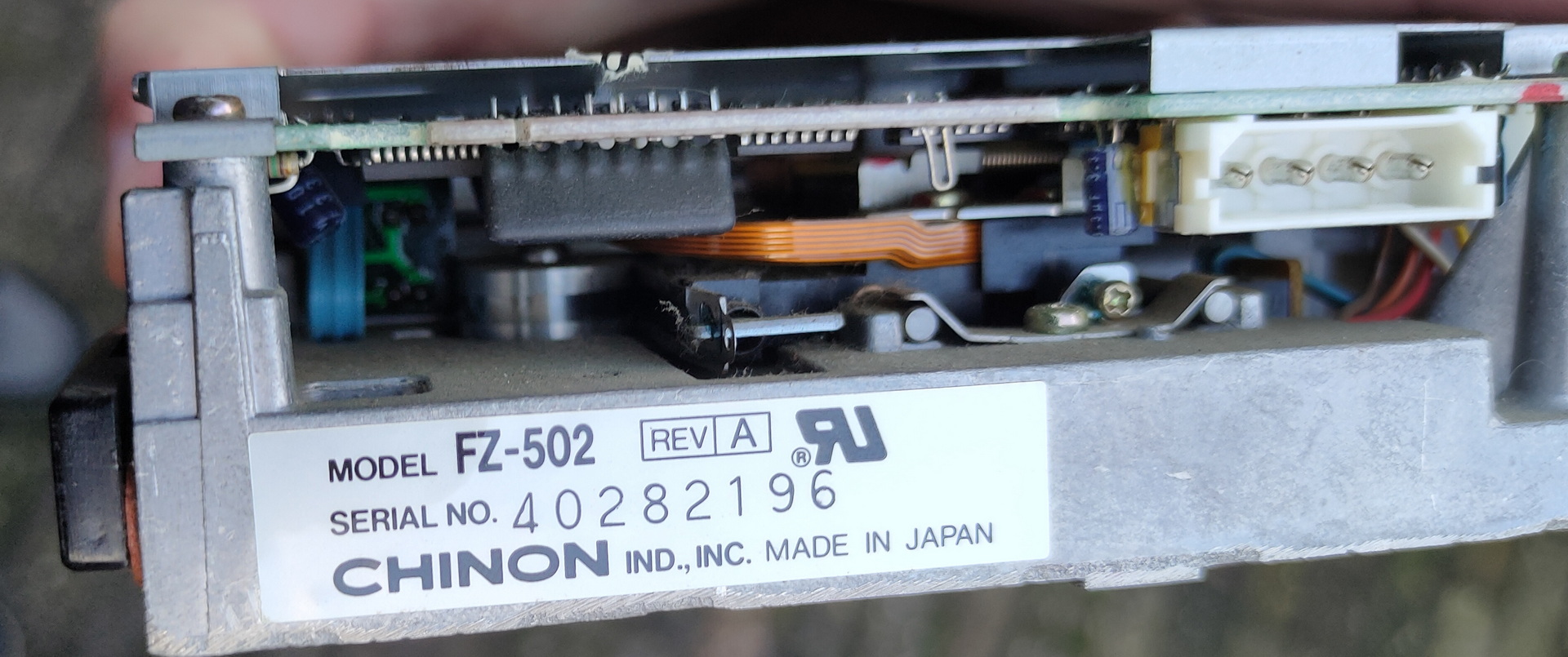
I see a led when it tries to boot, but my disks are probably formatted 720Kb instead of 360Kb, which this drive is.
So …. TODO!
Find a 720Kb floppy drive (5.25 inch), and sort through my code! There is a 8bit soundblaster compatible soundcard that i bidding on online, hopefully i’ll get it
Assembly and modes
I wasn’t sure how to sort the assembly code into Hercules and VGA compatible, but i used this table (There are also extended modes for higher resolutions)
mode 0x00
text 40×25 gray
mode 0x01
text 40×25 16 colors
mode 0x02
text 80×25
mode 0x03
text 80×25 16 color
mode 0x04
graphics mode (CGA) 320×200
mode 0x05
graphics mode (CGA) 320×200
mode 0x06
graphics mode (CGA) 640×200 (B/W)
mode 0x07
text 80×25 Hercules
mode 0x0F
graphics mode 640×350? gray
mode 0x10
graphics mode 640×350?
mode 0x11
graphics vga 2 colors
mode 0x12
graphics vga 16 colors
mode 0x13
graphics 320×200 256 colors
# Set VGA mode
    mov ax,13h
    int 10h         ;screen 320x200 256 colours

# Exit VGA mode
    mov ax,3
    int 10h         ;screen  80x25 text
    mov ax,4c00h
    int 21h         ;back to DOS
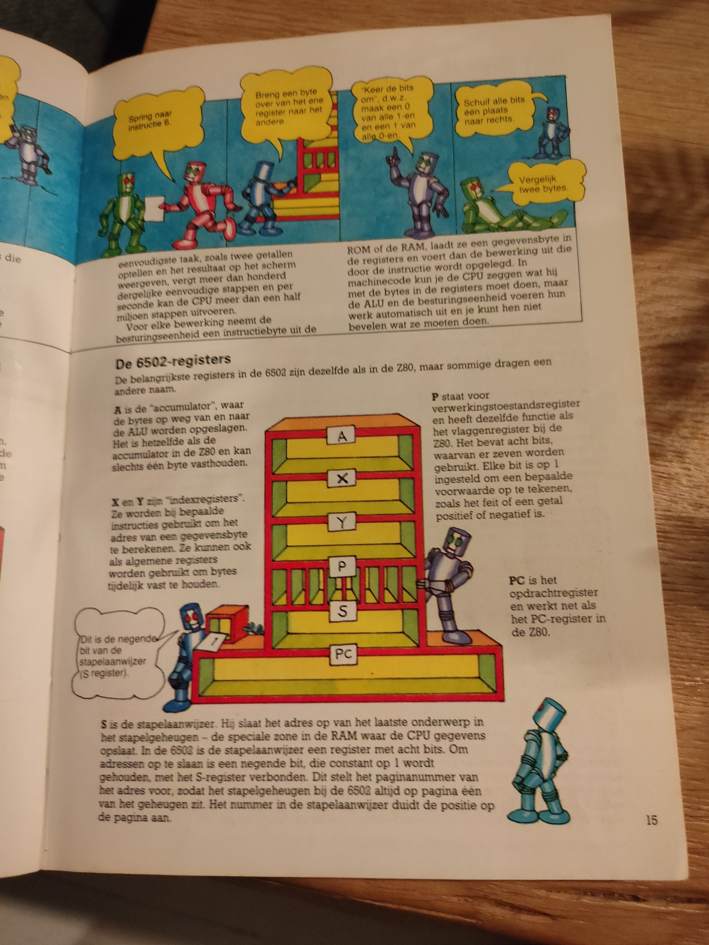
I’ve used a basic program on C64 in the past and a Cartridge machinecode monitor in the past. I’ve really forgotten how, what i’ve used and what i’ve done with it. Not nearly as much as my friends at that time. I started with a Vic-20 and played around with machinecode on a 6502. I didn’t have a C64 for many years.
How much funit this!
I’ve recently started to build a 6502 computer again, and programming on 65xx again (Generic 6502 and C64). (2022)
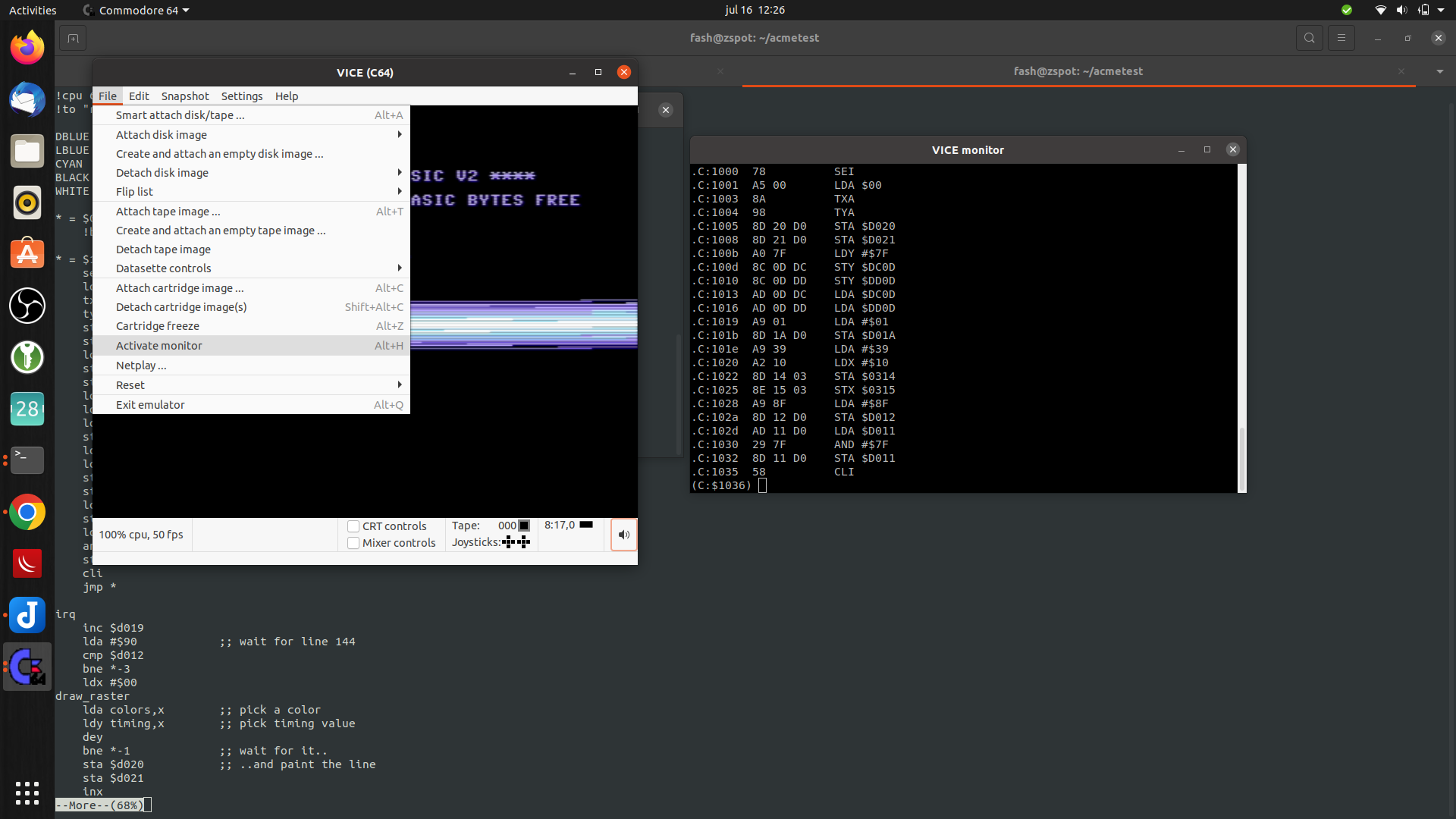
Below is my setup on linux, to write assembly code, compiling and running the code in a emulator.
I have installed the Acme compiler and Vice as a emulator. Both can compile/run machinecode for multiple computer emulations. So maybe i can run my old Vic-20 machine code or the few C64 programs i’ve written.
I’ve only made the bash script, the included asm files i copied from someone on the internet. ( Credit lookup )
makeprg bash file:
#!/bin/bash
set -x
f=""
if [ "$2" == "f" ] ; then f="-fullscreen" ; fi
if [ ! -f $1.asm ] ; then
cp template.asm $1.asm
fi
vi $1.asm
acme --cpu 6510 --format cbm --outfile $1.prg $1.asm
if [ ! $? -eq 0 ] ; then exit 1 ; fi
c1541 -format foo,id d64 $1.d64 -write $1.prg
if [ ! $? -eq 0 ] ; then exit 1 ; fi
x64 $f $1.prg
template.asm
!source "basic-boot.asm"

+start_at $0900

; Set background and border to black
ldx #$00
stx bgcol
stx bocol

; Flicker border and background
.loop
  inc bgcol
  inc bocol
  jmp .loop
basic-boot.asm
; A BASIC booter, encodes `10 SYS <address>`.
; Macroified from http://www.pouet.net/topic.php?which=6541

!source "constants.asm"

!macro start_at .address {
  * = basic
  !byte $0c,$08,$00,$00,$9e
  !if .address >= 10000 { !byte 48 + ((.address / 10000) % 10) }
  !if .address >=  1000 { !byte 48 + ((.address /  1000) % 10) }
  !if .address >=   100 { !byte 48 + ((.address /   100) % 10) }
  !if .address >=    10 { !byte 48 + ((.address /    10) % 10) }
  !byte $30 + (.address % 10), $00, $00, $00
  * = .address
}

; A cooler example is to write
;
;   10 SYS <address>: REM <backspaces>Your comment
;
; When the user types LIST, he will just see
;
;   10 Your comment
;
; but still be able to run it.
; For this, see http://codebase64.org/doku.php?id=base:acme-macro-tu
When running above bash script. it will open the file if it exists, else it will take a template file. After opening it with vi, and editing it, it starts a the compiler and creates a C64 d64 disk. This is going to be autorun/started with the VIce emulator. Appending -f to the bash script will start it in fullscreen mode. ./makeprg myawesomedemo.asm -f
Below it is running without the fullscreen option. but is shows how to start the interactive monitor in vice.
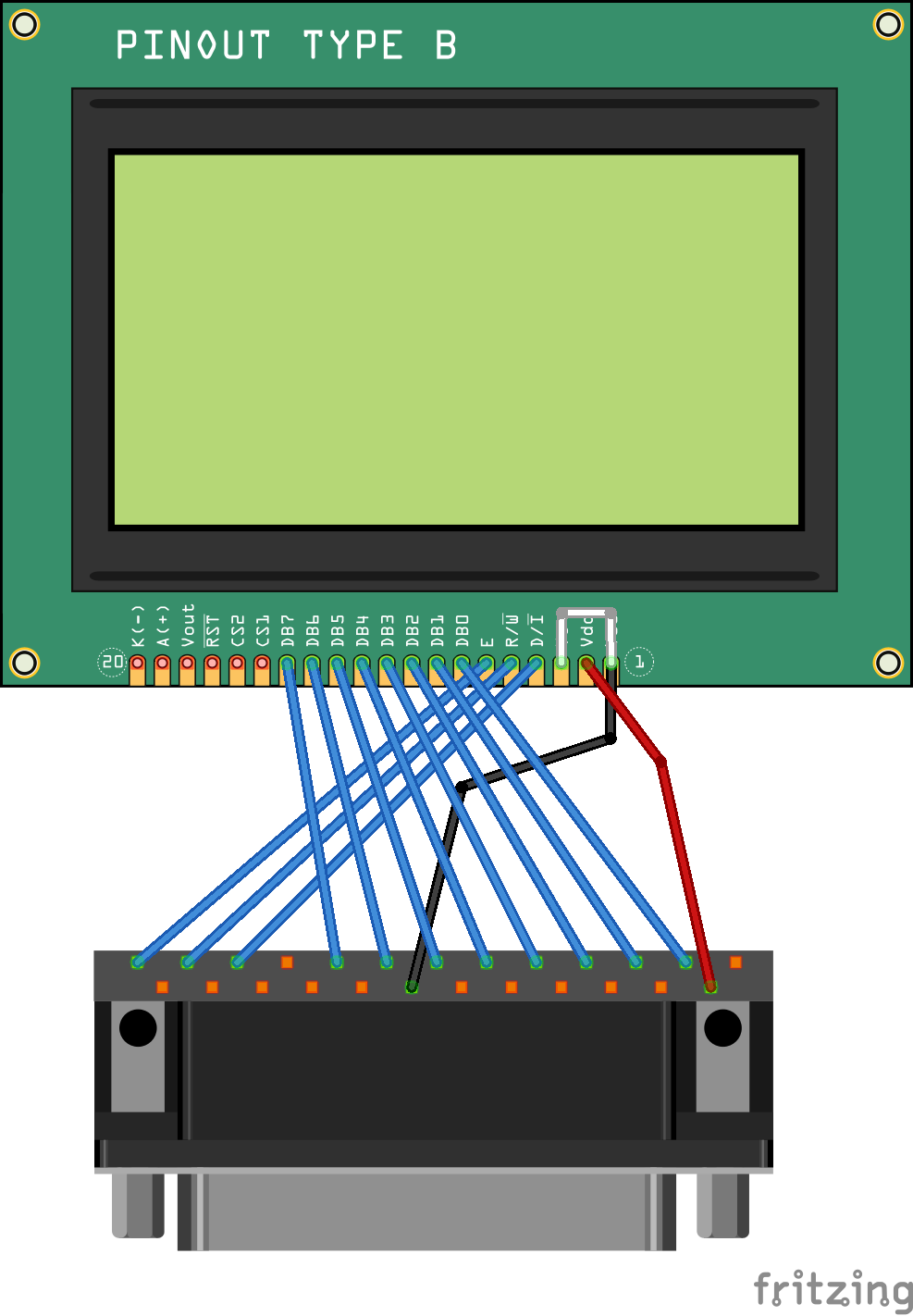
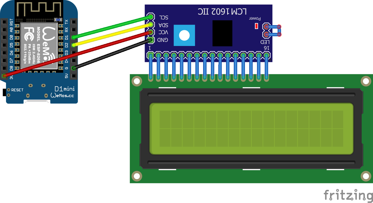
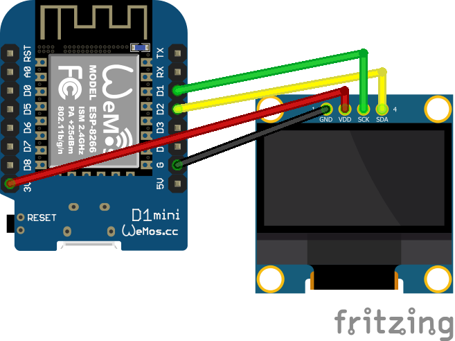
Below some examples and connection diagrams to control displays. More code and complete schematics will be added on this page or on a separate projects page.
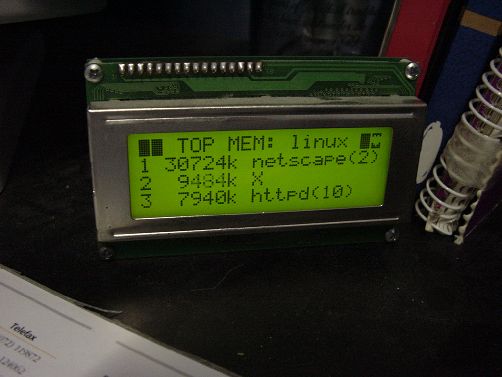
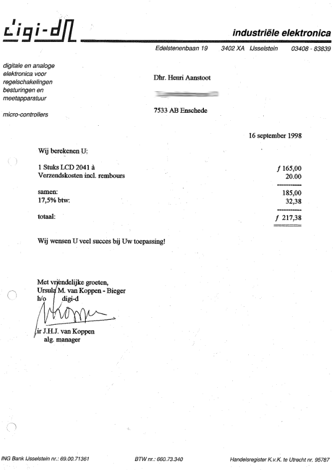
UPDATE 20230119 Cost of 20×4 display in 1998
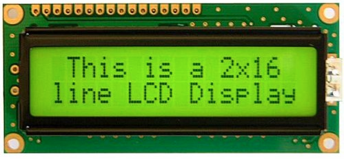
LCD
I’ve used a LCD display like this (HITACHI HD44780) on my PC in the 90s, and also written code to use this as a monitoring device on my amiga.
On Linux i used LcdProc – This module also was equiped with a serial connector
Now (2023) it is 8 euros! When bought now fl to euro 98 Euro or 107 $
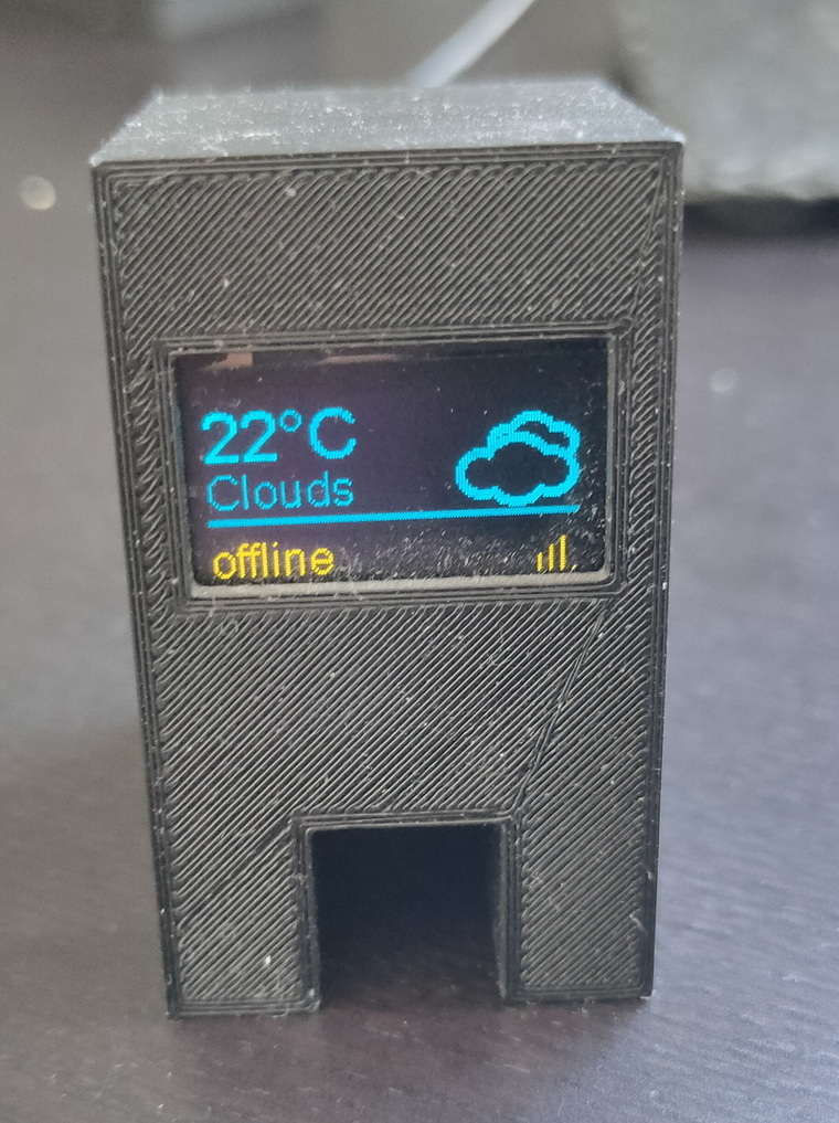
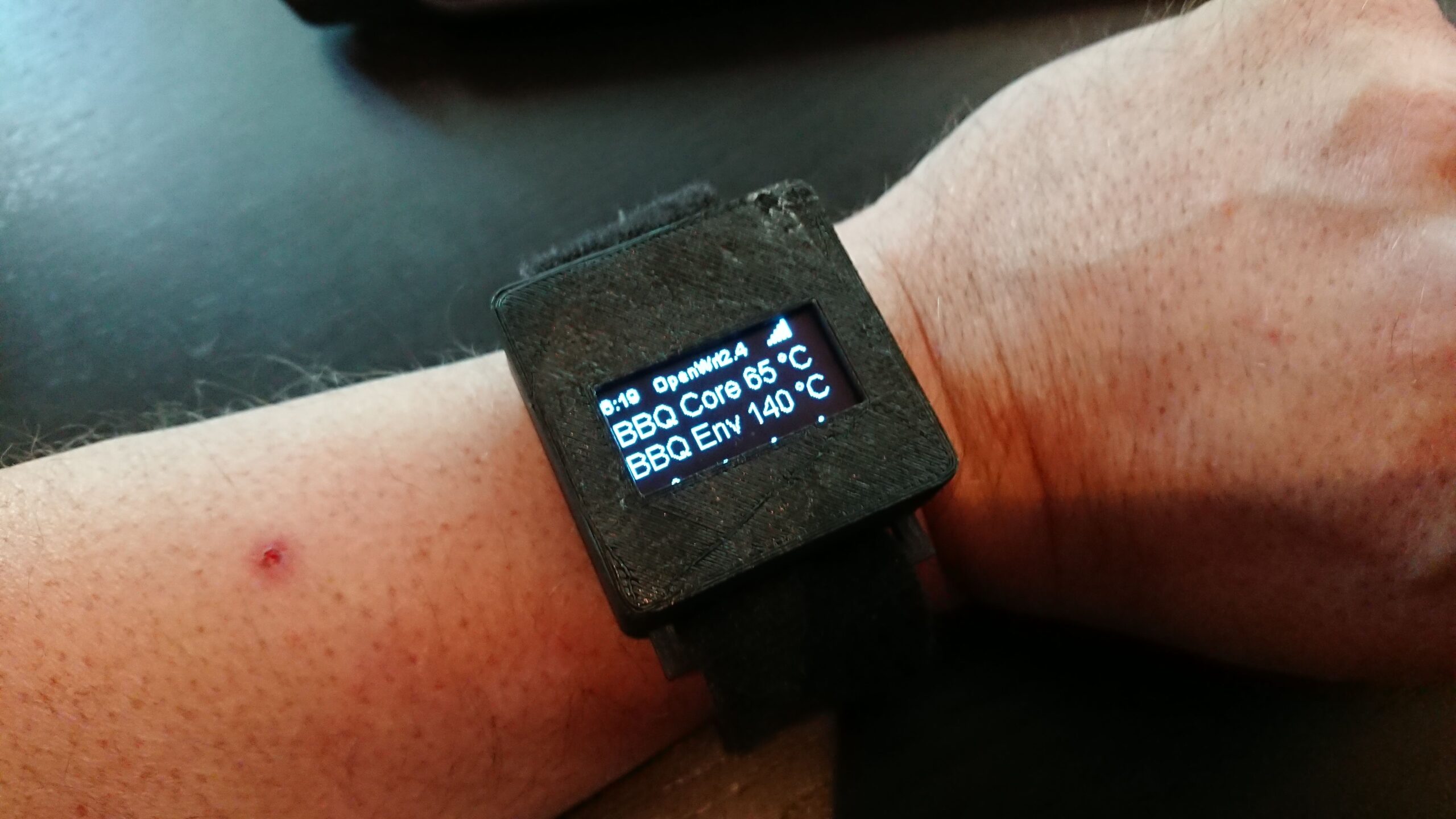
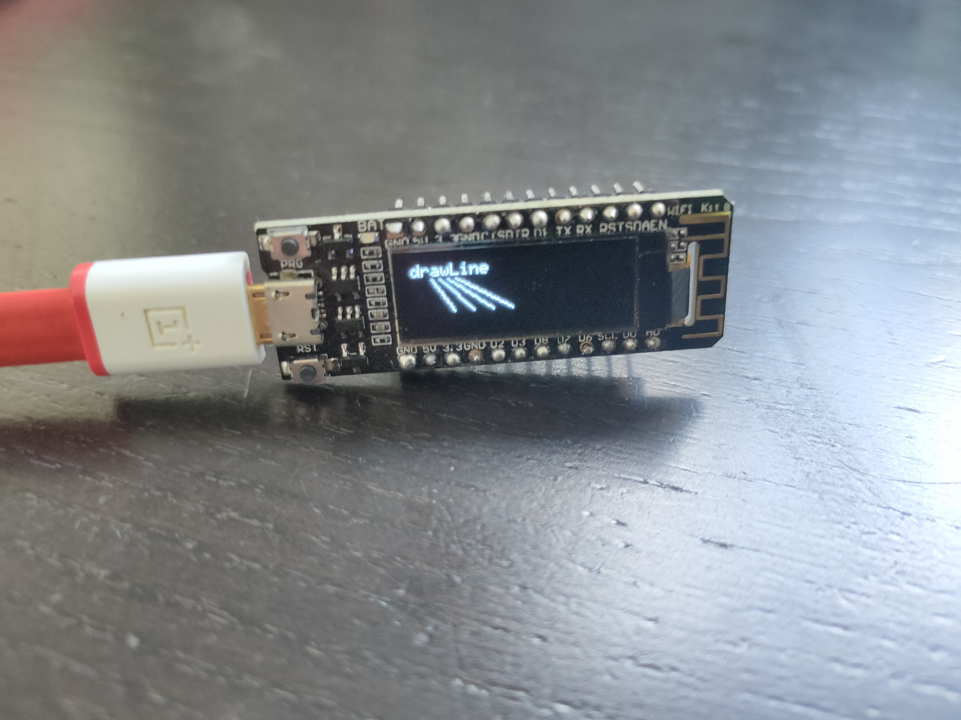
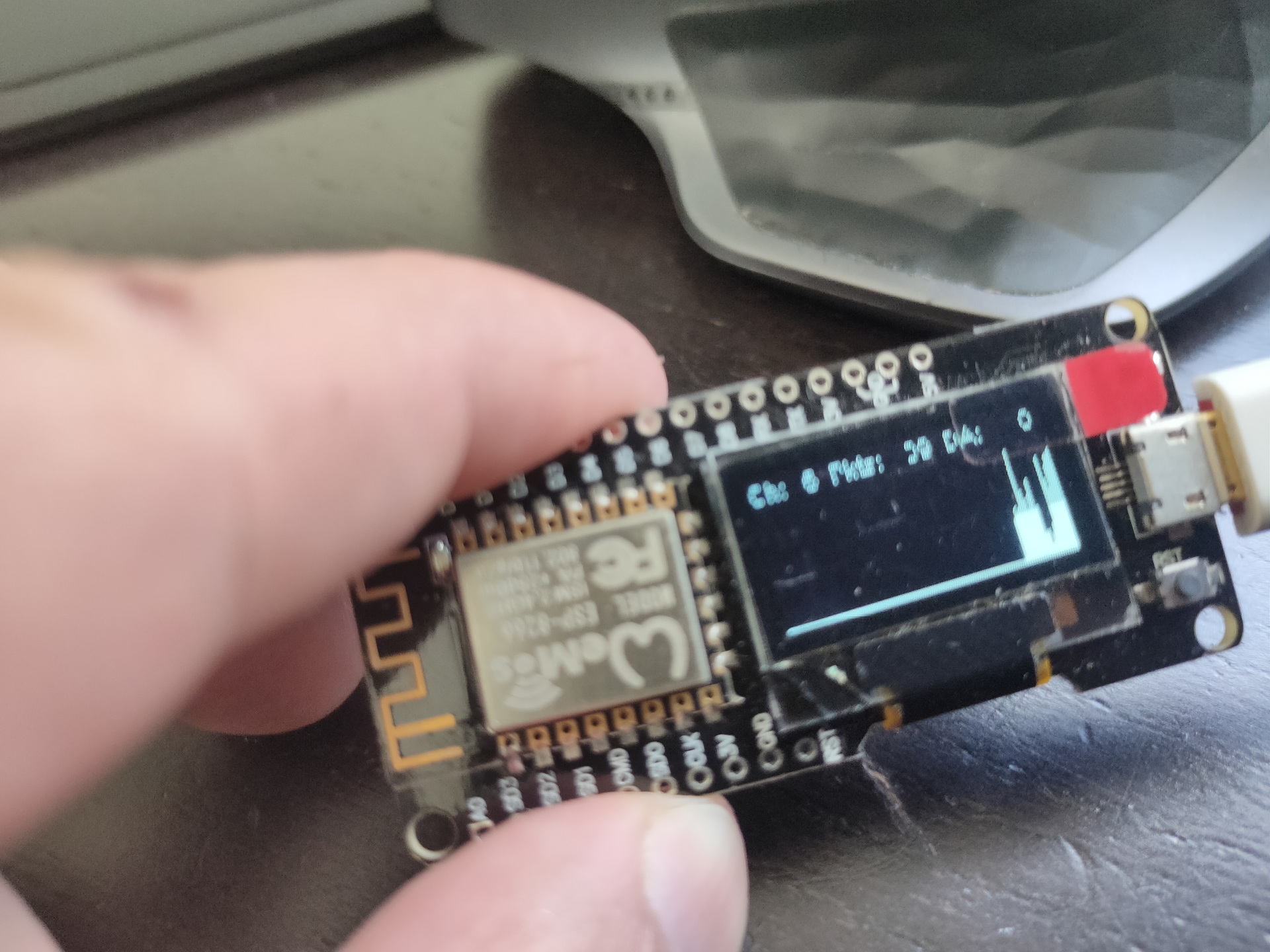
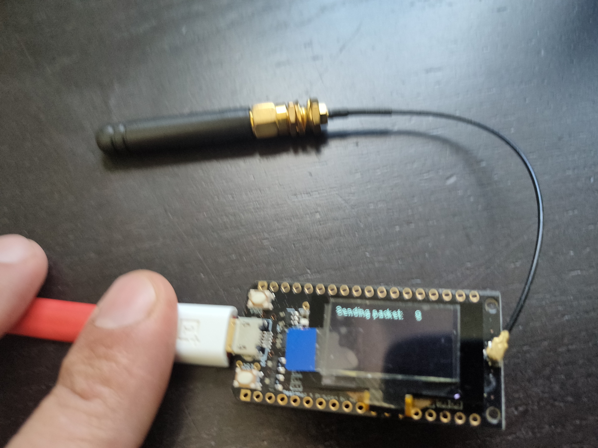
Some arduino’s have embedded displays like those i’ve used for a Lora project.
No usedWifi packet monitorLora test
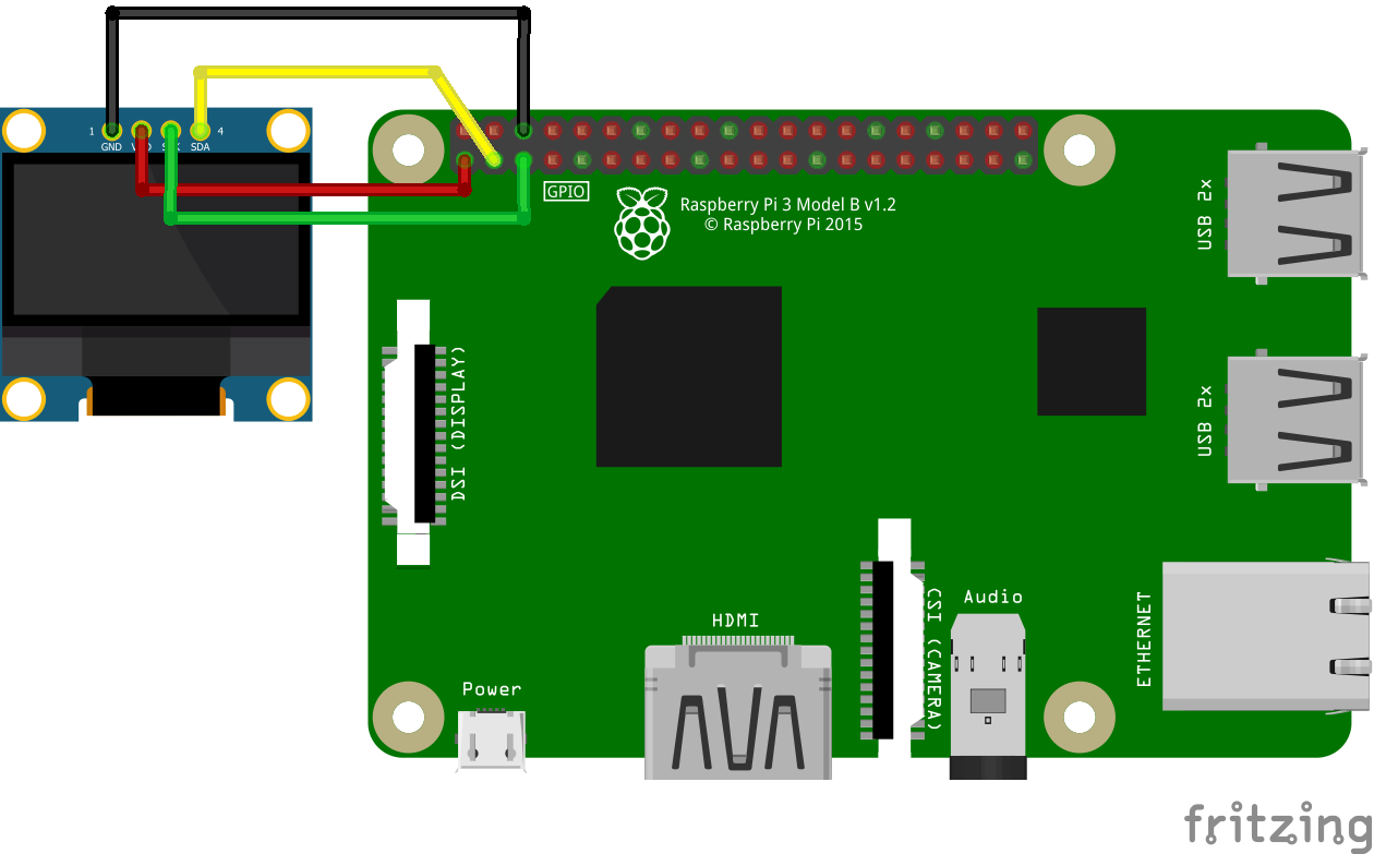
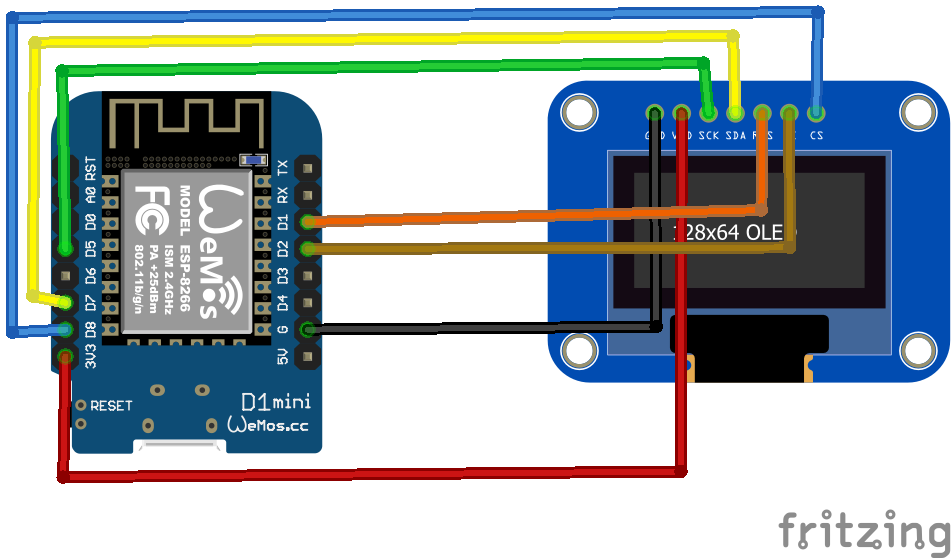
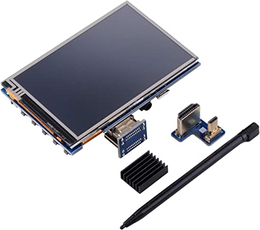
Other means of connecting : SPI
SPI connected display
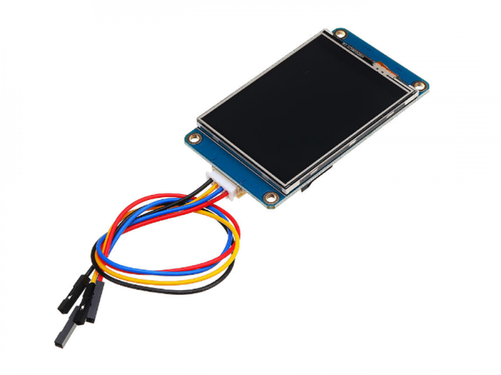
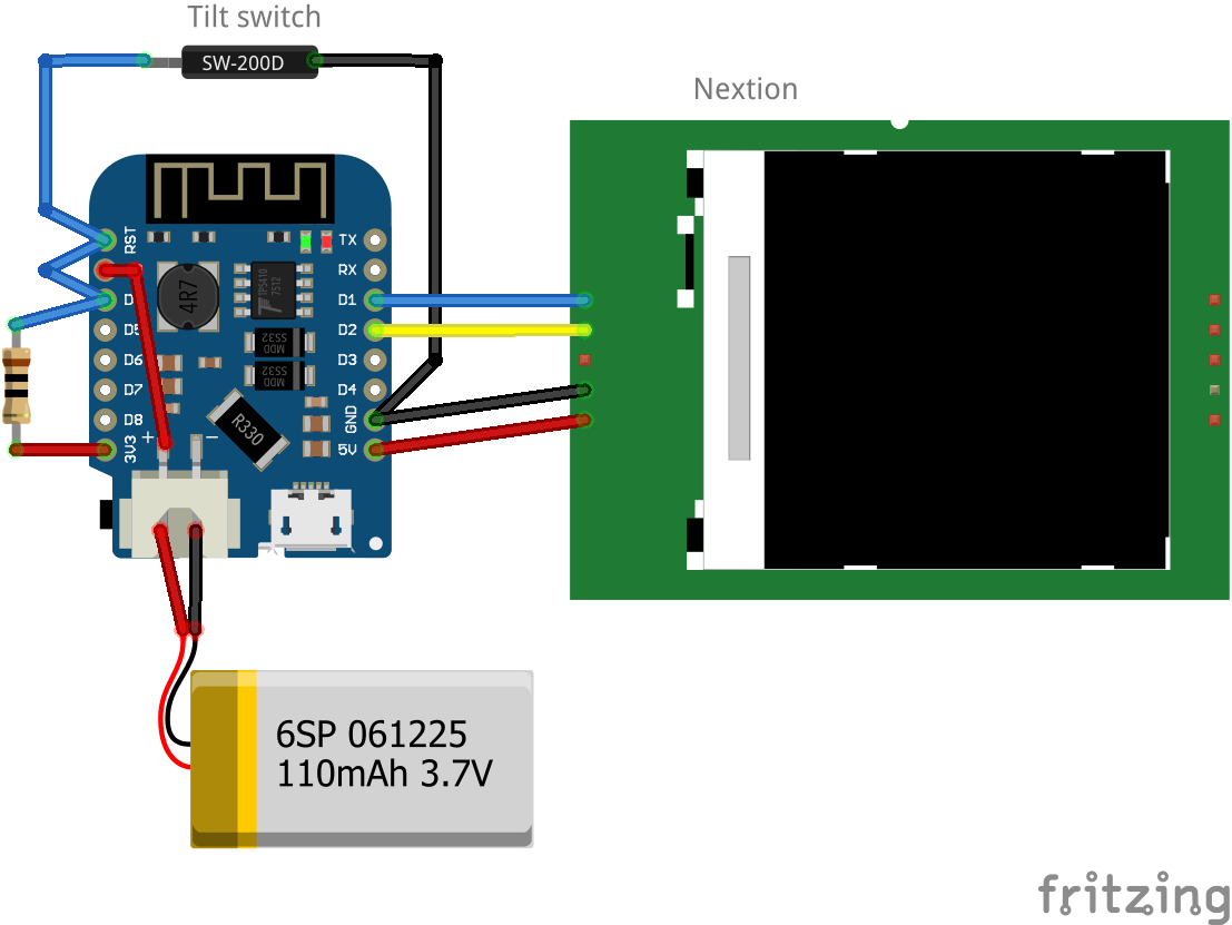
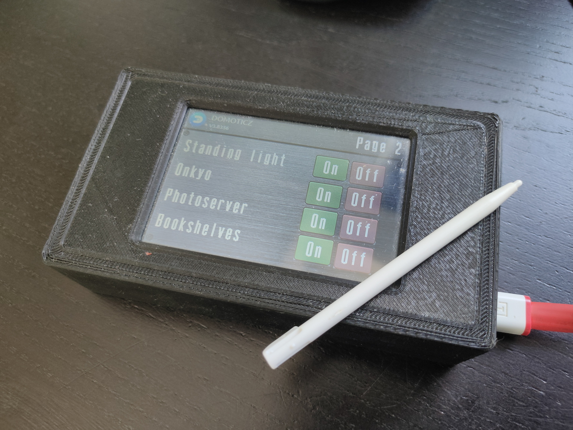
Nextion
Nextion is a Human Machine Interface (HMI) solution combining an onboard processor and memory touch display with Nextion Editor software for HMI GUI project development.
Using the Nextion Editor software, you can quickly develop the HMI GUI by drag-and-drop components (graphics, text, button, slider, etc.) and ASCII text-based instructions for coding how components interact on the display side.
Nextion HMI display connects to peripheral MCU via TTL Serial (5V, TX, RX, GND) to provide event notifications that peripheral MCU can act on, the peripheral MCU can easily update progress, and status back to Nextion display utilizing simple ASCII text-based instructions.
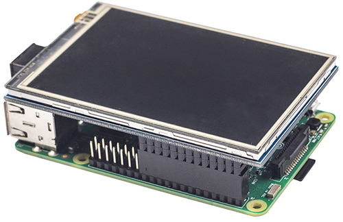
edit cmdline.txt
add "fbcon=map:10 fbcon=font:ProFont6x11 logo.nologo"
at the end
edit config.txt
add between custom comments at the bottom
dtoverlay=piscreen,speed=24000000,rotate=90
# Or check http://www.lcdwiki.com/3.5inch_RPi_Display
Above display’s i’ve used for Picore Players and the Lidar POC
To try: Getting above display running with a arduino https://github.com/PaulStoffregen/XPT2046_Touchscreen
Raspberry HDMI display
Easiest of them all, just connect with HDMI, there is a adaptor for hdmi-hdmi (versions 1,2,3) and hdmi-mini-hdmi for RPi4 variants.
Epaper and 7-Segment displays
Other means of displaying information are for example
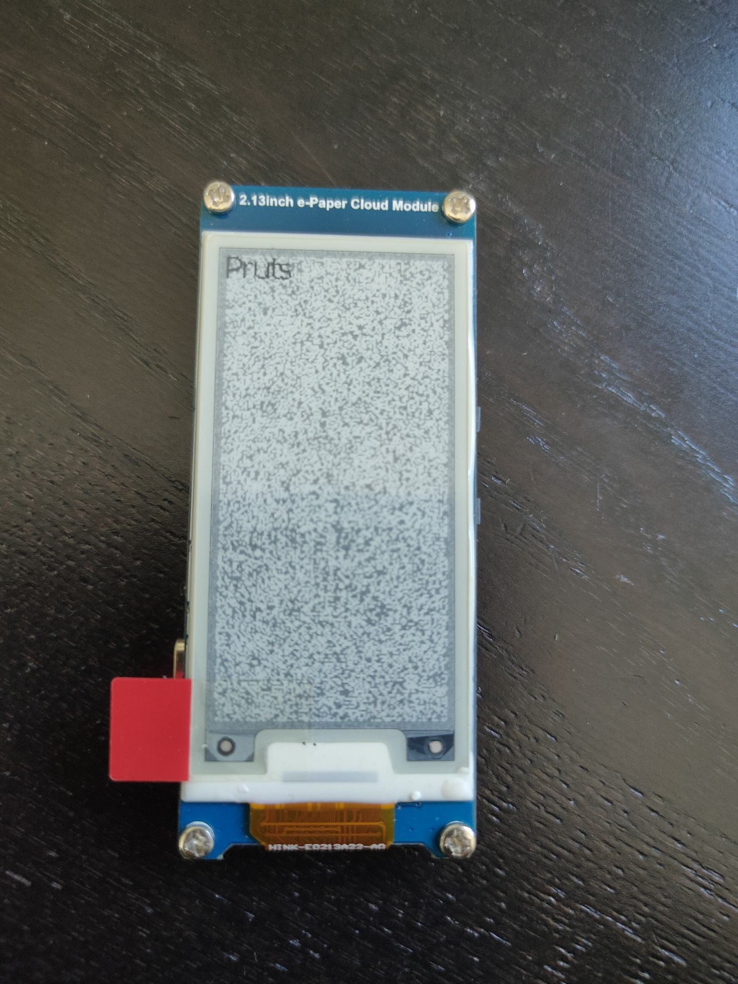
Epaper
ESP with epaper module, disconnected power for a while, artifacts appear.
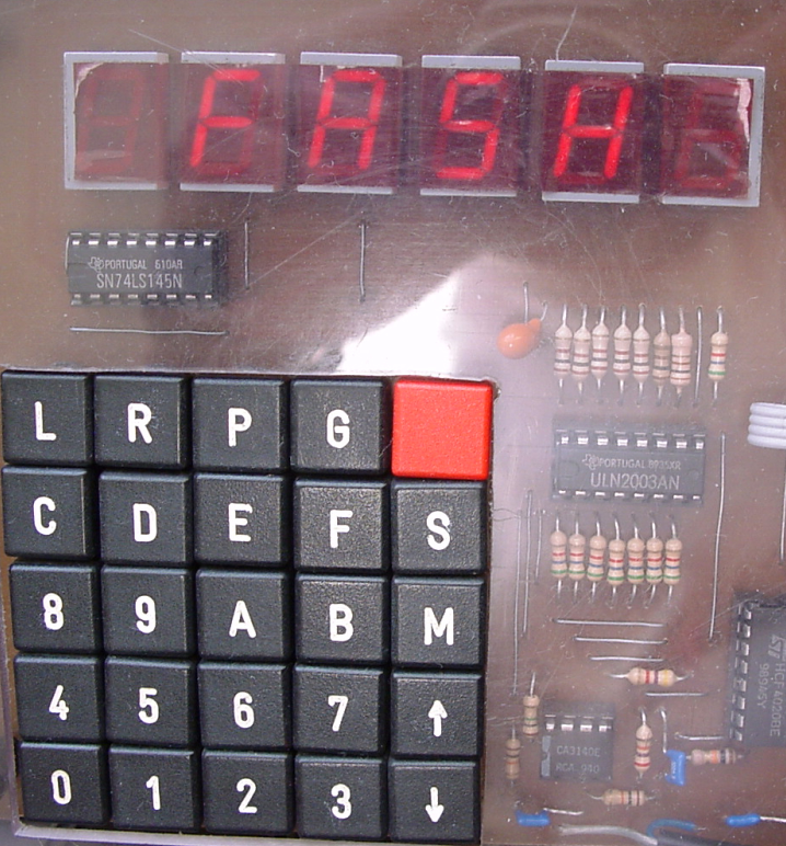
7 Segment displays
I used a lot of 7-Segment display’s in the past. They look cool and are hardcore.
My homebrew computer uses this
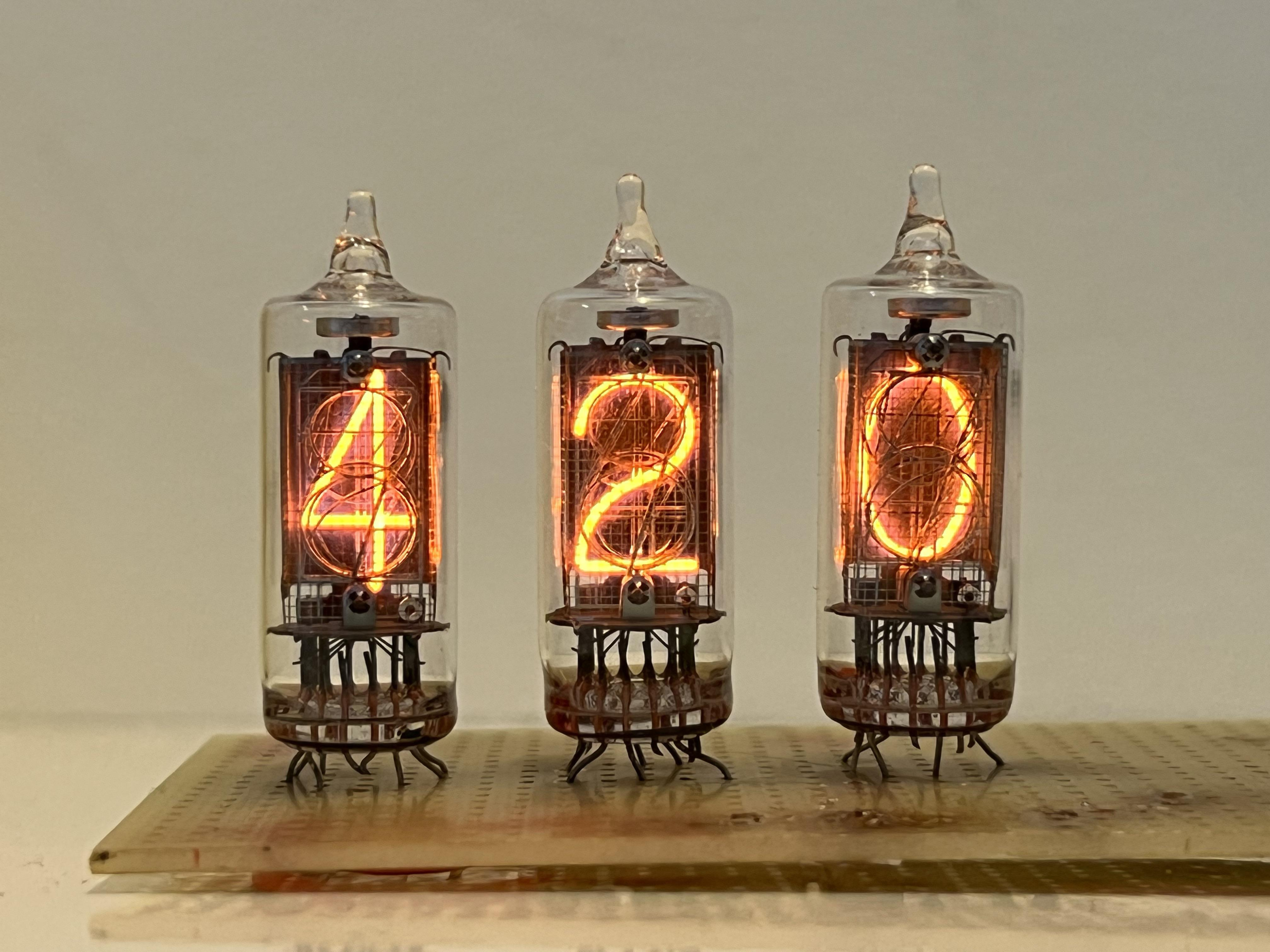
Nixie tubes!
And there are https://en.wikipedia.org/wiki/Nixie_tube .. I’ve never had those
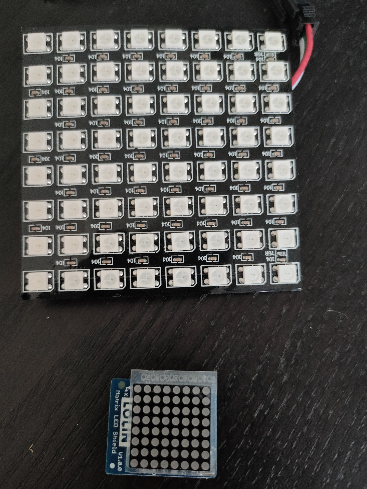
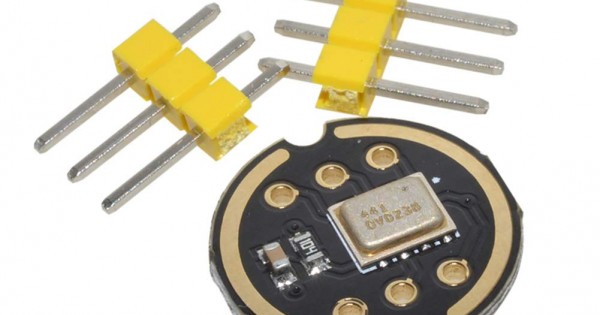
Above bigger 2D display i used with Wled and a digital microphone, so its sound reactive. The lower part i got in recently .
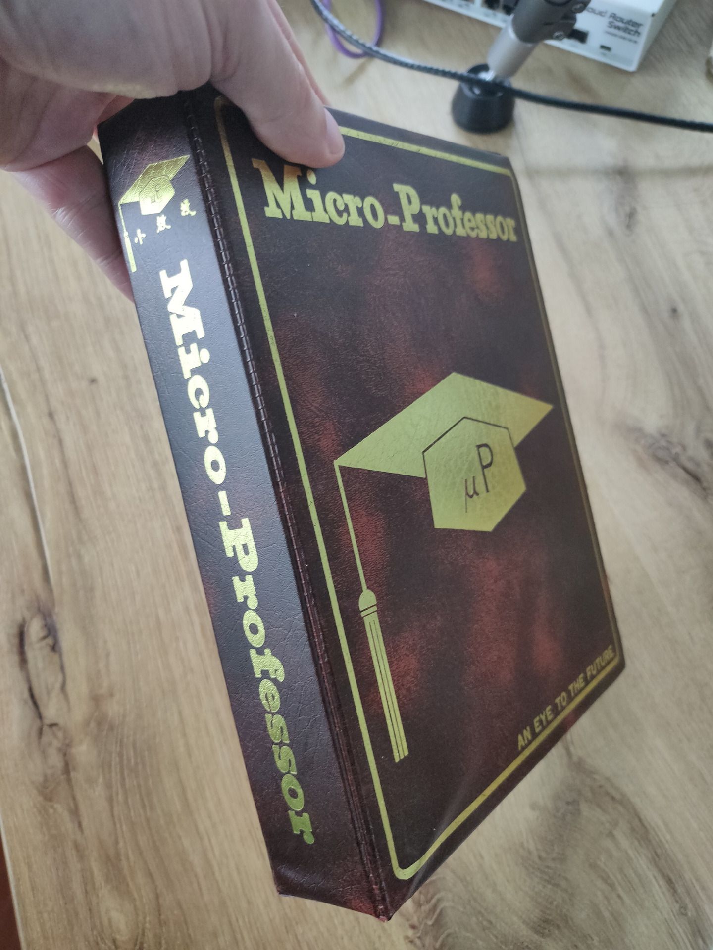
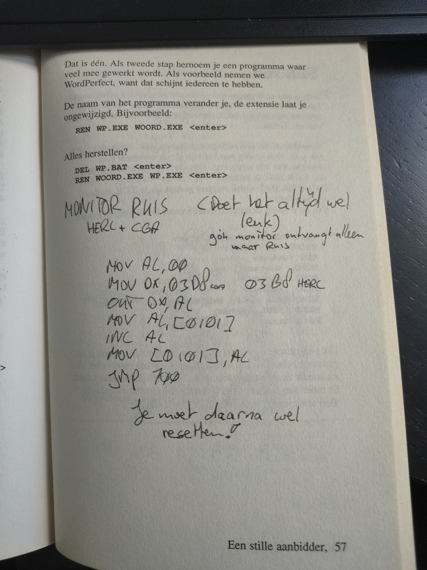
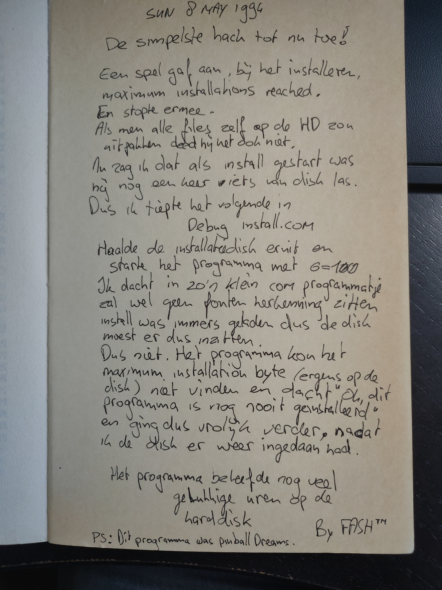
A long time ago i took a book about doing funny stuff in dos, and wrote own additions in the sidelines of the book. Or used the empty pages.
It contains jokes using autoexec.bat and config.sys. Additions by me are most of the time things you could do with debug.com, a little program which existed on any pc at that time.
A little program which created static on a CGA or Hercules monitor. Yes, that long ago. CGA provided 16 colors in 80×25 or 40×25 text modes, but only four colors at 320×200 resolution and two colors at 640×200. Hercules was only monochrome and a max resolution of 720×348. It was on a hercules card i made my first copperbar. ( Before the effect was named copperbar ). Due to difference in timing on every machine, you had to get the copperbar timing right by using two keys i’d assigned the timing to.
MOV AL,00                      # Fill AL register with 0
MOV DX,0x03D8 (cga) 03B8 (herc)# DX with address
OUT DX,AL                      # Set address with AL
MOV AL,[0101]                  # Reg AL with contents
INC AL                         # Increment AL
MOV [0101],AL                  # Address fill with AL
JMP 100                        # Jump to start
The opcodes for the program :
b0 00
66 ba d8 03
ee
a0 41 00 00 00
fe c0
a2 41 00 00 00
e9 60 00 00 00
Sometimes i put these little programs in autoexec.bat, so at next restart of the pc, it would do something weird. My little BOFH jokes. Friends and computerstores where not safe.
Another example:
Two drives in a PC ? (Wie A: zegt moet ook B: zeggen) Use with care, below will f*ck up your drives. (And makes a lot of noise while doing so.)
MOV DX,0x03F2
MOV AL,71
OUT DX,AL
MOV AL,74
OUT DX,AL
JMP 100
20220502: Fixed another C64, PIA (Peripheral Interface Adapter) was dead, luckily i’ve got several spare-part c64’s. So that was a easy fix.
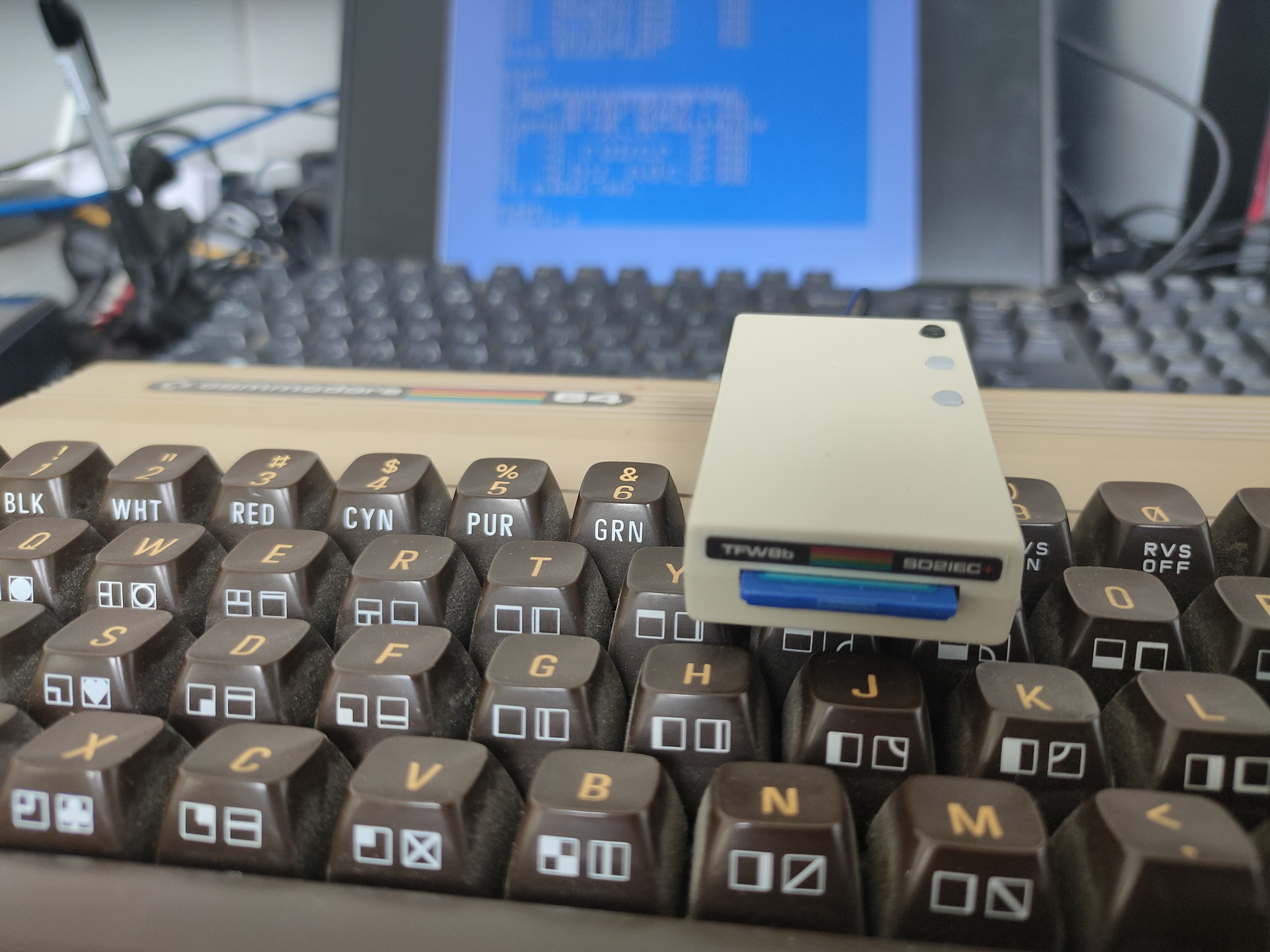
20220504: Got my sd2iec adaptor in, see bottom of this page.
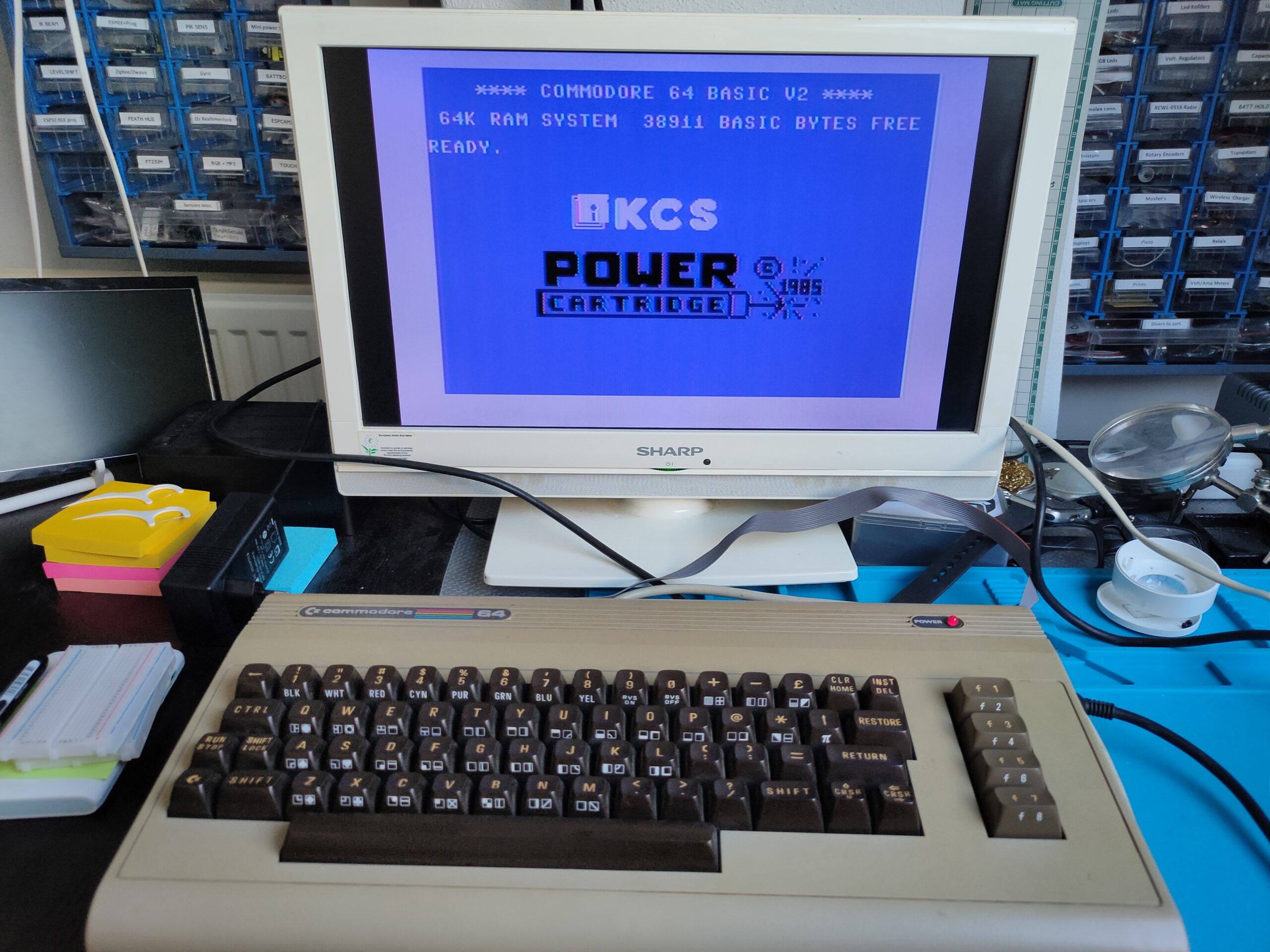
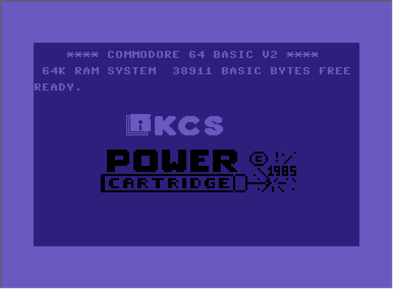
Booting with a power cartridge
None of my old computers was unmodified
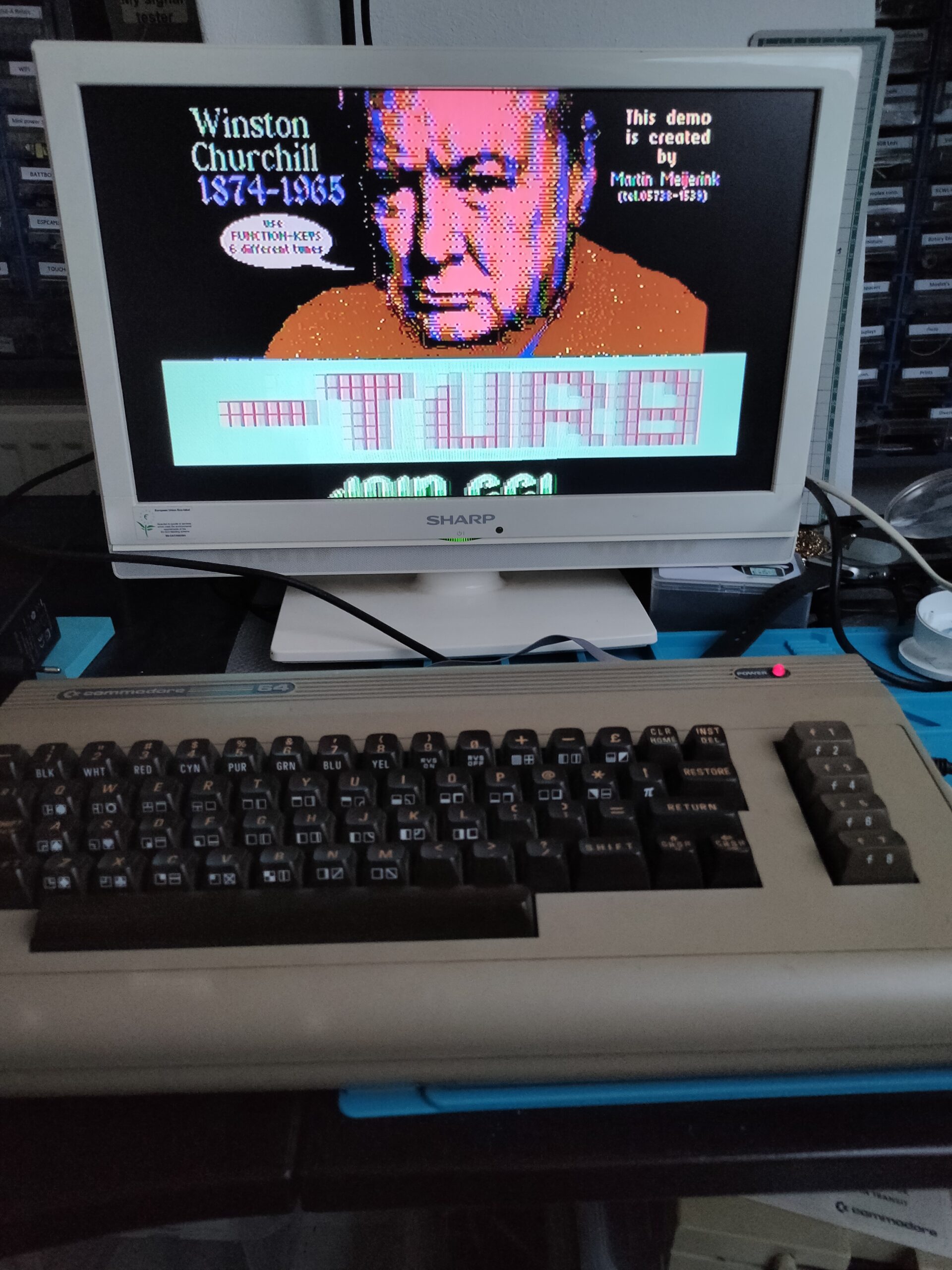
Demo by my old friend Sepp
Drive is a 1541model 2
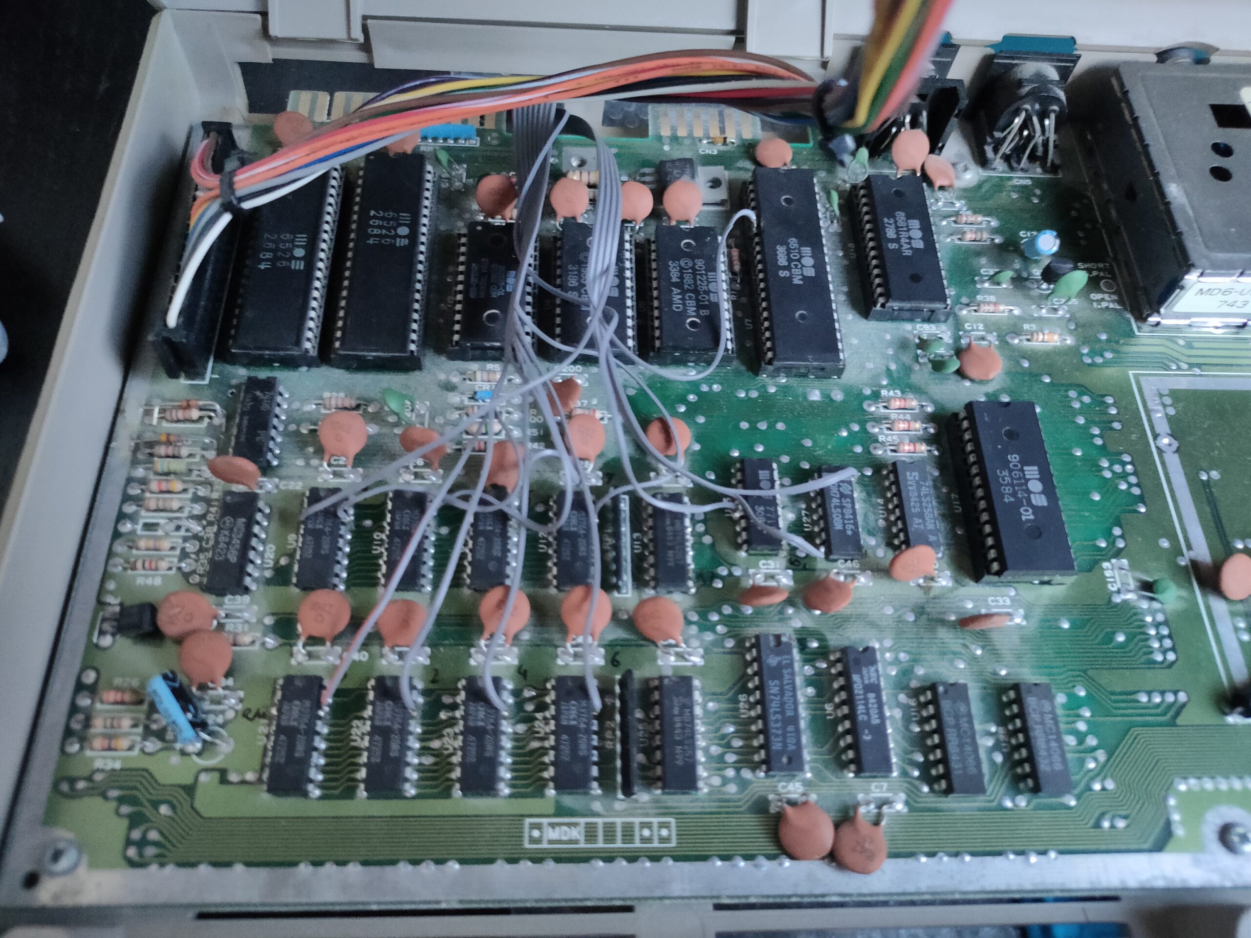
De wires are going to the DOUT pins of the memory chips. Showing activity using leds. Sometimes i monitored CS .. also informative.
SD2IES Cardreader
Little small funky gadget, it replaces a 1541 Floppy drive with a SDCard reader where you can store a lot of floppydisk images on. More on this later.
NOTE : Doesn’t work together with my KCS Power cartridge.
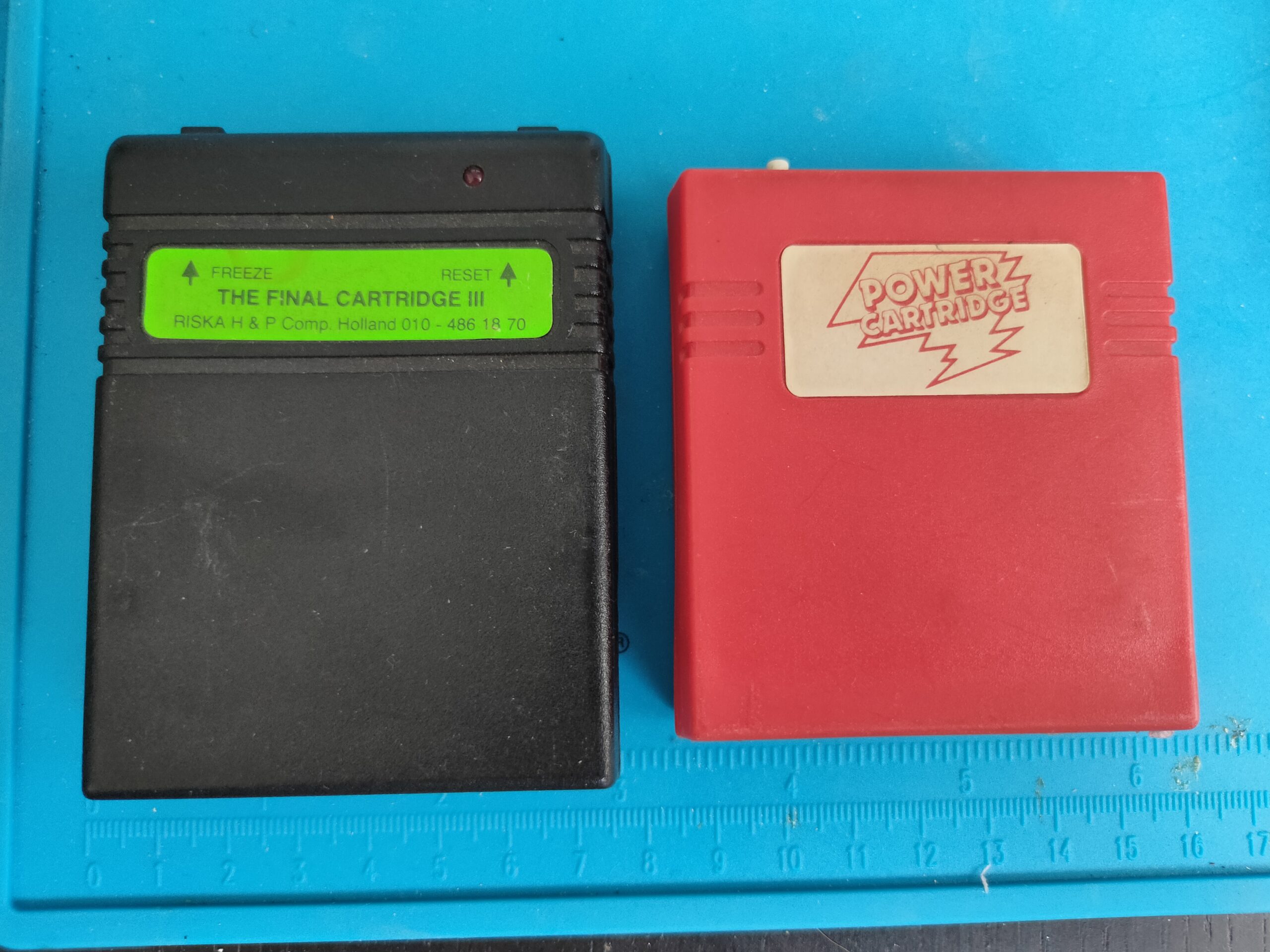
CartridgeScreen
I’ve tested two cartridges.
Final cartridge III fastload test on a program did ~3 seconds. ( Normal load time ~17 seconds. ) KCS powercartridge didn’t work. Tip: press `runstop` when using FC3 while turning on to get into basic not the desktop.
o = out
port 0x0070-0x0071	The CMOS and RTC registers (more info below)
# Does not seem related but it works!


-o 70 2E
-o 71 FF
-q

OR

-o 70 17
-o 71 17
-q
Other fixes i’ve used:
Remove cmos battery .. and short the connections with wire. This CAN completely reset your Bios settings!
0070-007F ----	CMOS RAM/RTC (Real Time Clock  MC146818)

0070	w	CMOS RAM index register port (ISA, EISA)
		 bit 7	 = 1  NMI disabled
			 = 0  NMI enabled
		 bit 6-0      CMOS RAM index (64 bytes, sometimes 128 bytes)

		any write to 0070 should be followed by an action to 0071
		or the RTC wil be left in an unknown state.

0071	r/w	CMOS RAM data port (ISA, EISA)
		RTC registers:
		00    current second in BCD
		01    alarm second   in BCD
		02    current minute in BCD
		03    alarm minute   in BCD
		04    current hour in BCD
		05    alarm hour   in BCD
		06    day of week  in BCD
		07    day of month in BCD
		08    month in BCD
		09    year  in BCD (00-99)
		0A    status register A
		       bit 7 = 1  update in progress
		       bit 6-4 divider that identifies the time-based
				frequency
		       bit 3-0 rate selection output  frequency and int. rate
		0B    status register B
		       bit 7 = 0  run
			     = 1  halt
		       bit 6 = 1  enable periodic interrupt
		       bit 5 = 1  enable alarm interrupt
		       bit 4 = 1  enable update-ended interrupt
		       bit 3 = 1  enable square wave interrupt
		       bit 2 = 1  calendar is in binary format
			     = 0  calendar is in BCD format
		       bit 1 = 1  24-hour mode
			     = 0  12-hour mode
		       bit 0 = 1  enable daylight savings time. only in USA.
				  useless in Europe. Some DOS versions clear
				  this bit when you use the DAT/TIME command.
		0C    status register C
		       bit 7 =	  interrupt request flag
		       bit 6 =	  peridoc interrupt flag
		       bit 5 =	  alarm interrupt flag
		       bit 4 =	  update interrupt flag
		       bit 3-0	  reserved
		0D    status register D
		       bit 7 = 1  Real-Time Clock has power
		       bit 6-0	  reserved
		0E    diagnostics status byte
		       bit 7 = 0  RTC lost power
		       bit 6 = 1  CMOS RAM checksum bad
		       bit 5 = 1  invalid configuration information at POST
		       bit 4 = 1  memory size error at POST
		       bit 3 = 1  fixed disk/adapter failed initialization
		       bit 2 = 1  CMOS RAM time found invalid
		       bit 1 = 1  adapters do not match configuration (EISA)
		       bit 0 = 1  time out reading an adapter ID (EISA)
		0F    shutdown status byte
		       00 = normal execution of POST
		       01 = chip set initialization for real mode reentry
		       04 = jump to bootstrap code
		       05 = issue an EOI an JMP to Dword ptr at 40:67
		       06 = JMP to Dword ptrv at 40:67 without EOI
		       07 = return to INT15/87 (block move)
		       08 = return to POST memory test
		       09 = return to INT15/87 (block move)
		       0A = JMP to Dword ptr at 40:67 without EOI
		       0B = return IRETS through 40:67
		10    diskette drive type for A: and B:
		       bit 7-4	drive type of drive 0
		       bit 3-0	drive type of drive 1
			       = 0000	   no drive
			       = 0001	   360K
			       = 0010	   1M2
			       = 0011	   720K
			       = 0100	   1M44
			       = 0101-1111 reserved
		11    reserved / AMI Extended CMOS setup (AMI Hi-Flex BIOS)
		       bit 7   = 1     Typematic Rate Programming
		       bit 6-5 = 00    Typematic Rate Delay 250 mSec
		       bit 4-0 = 00011 Typematic Rate 21.8 Chars/Sec
		12    fixed disk drive type for drive 0 and drive 1
		       bit 7-4	drive type of drive 0
		       bit 3-0	drive type of drive 1
				if either of the nibbles equals 0F, then bytes
				19 an 1A are valid
		13    reserved / AMI Extended CMOS setup (AMI Hi-Flex BIOS)
		       bit 7 = 1  Mouse Support Option
		       bit 6 = 1  Above 1 MB Memory Test disable
		       bit 5 = 1  Memory Test Tick Sound disable
		       bit 4 = 1  Memory Parity Error Check enable
		       bit 3 = 1  Hit <ESC> Message Display disabled
		       bit 2 = 1  Hard Disk Type 47 Data Area at address 0:300
		       bit 1 = 1  Wait For <F1> If Any Error enabled
		       bit 0 = 1  System Boot Up Num Lock is On
		14    equipment byte
		       bit 7-6	 diskette drives installed
			       = 00  1 drive installed
			       = 01  2 drives installed
			       = 10  reserved
			       = 11  reserved
		       bit 5-4	 primary display
			       = 00  adapter card with option ROM
			       = 01  40*25 color
			       = 10  80*25 color
			       = 11  monochrome
		       bit 3-2	 reserved
		       bit 1   = 1  coprocessor installed (non-Weitek)
		       bit 0	    diskette drive avaliable for boot
		15    LSB of systemn base memory in Kb
		16    MSB of systemn base memory in Kb
		17    LSB of total extended memory in Kb
		18    MSB of total extended memory in Kb
		19    drive C extension byte
		1A    drive D extension byte
		1B-27 reserved
		1B/1C word to 82335 RC1 roll compare register at [24]
			(Phoenix)
		1D/1E word to 82335 RC2 roll compare register at [26]
			(Phoenix)
		28    HP-Vectra checksum over 29-2D
		29-2D reserved
		29/2A word to Intel 82335 CC0 compare register at
			[28](Phoenix)
		2B/2C word send to 82335 CC1 compare register at [2A]
			(Phoenix)
		2D    AMI Extended CMOS setup (AMI Hi-Flex BIOS)
		      (Phoenix BIOS checks for the values AA or CC)
		       bit 7 = 1  Weitek Processor Absent
		       bit 6 = 1  Floppy Drive Seek At Boot disabled
		       bit 5 = 1  System Boot Up Sequence  C:, A:
		       bit 4 = 1  System Boot Up Speed is high
		       bit 3 = 1  Cache Memory enabled
		       bit 2 = 1  Internal Cache Memory	 <1>
		       bit 1-0	  reserved
		2E    CMOS MSB checksum over 10-2D
		2F    CMOS LSB checksum over 10-2D
		30    LSB of extended memory found above 1Mb at POST
		31    MSB of extended memory found above 1Mb at POST
		32    date century in BCD
		33    information flags
		       bit4 = bit4 from CPU register CR0   (Phoenix)
			      this bit is only known as INTEL RESERVED
		34-3F reserved
		34     bit4 bit5 (Phoenix BIOS)
		3D/3E word to 82335 MCR memory config register at
			[22](Phoenix)
		3D     bit3	 base memsize 512/640  (Phoenix)
		3E     bit7 = 1	 relocate enable       (Phoenix)
		       bit1 = 1	 shadow video enable   (Phoenix)
		       bit0 = 1	 shadow BIOS enable    (Phoenix)


		User Definable Drive Parameters are also stored in CMOS RAM:

		AMI (386sx BIOS 1989) first user definable drive (type 47)
		 1B  L cylinders
		 1C  H cylinders
		 1D  heads
		 1E  L Write Precompensation Cylinder
		 1F  H Write Precompensation Cylinder
		 20  ??
		 21  L cylinders parking zone
		 22  H cylinders parking zone
		 23  sectors

		AMI (386sx BIOS 1989) second user definable drive (type 48)
		 24  L cylinders
		 25  H cylinders
		 26  heads
		 27  L Write Precompensation Cylinder
		 28  H Write Precompensation Cylinder
		 29  ??
		 2A  L cylinders parking zone
		 2B  H cylinders parking zone
		 2C  sectors

		Phoenix (386BIOS v1.10.03 1988) 1st user definable drv (type48)
		 20  L cylinders
		 21  H cylinders
		 22  heads
		 23  L Write Precompensation Cylinder
		 24  H Write Precompensation Cylinder
		 25  L cylinders parking zone
		 26  H cylinders parking zone
		 27  sectors

		Phoenix (386BIOS v1.10.03 1988) 2nd user definable drv (type49)
		(when PS/2-style password option is not used)
		 35  L cylinders
		 36  H cylinders
		 37  heads
		 38  L Write Precompensation Cylinder
		 39  H Write Precompensation Cylinder
		 3A  L cylinders parking zone
		 3B  H cylinders parking zone
		 3C  sectors
This year i’ve been really into assembly on Intel x86 machines. With EDK we made some demo’s and generally trying to find the limits of the machines we had.
Funny story, edk made a program which changed the palette every scanline (if memory serves me right), while running the program and looking at the screen the colors faded to grayscale. (Something with run-away tables) We look at eachother and said: We must have been using up all colors, we need to refill the graphics card.
I previously made a copperbar alike thingy on a hercules system. (Have not seen them before on a pc back then ) But with below program, i could display pictures which removed the borders.
Below a nsfw video example (pass protected), but a simplified example in pictures below that.
Test image i’ve used on a 320×200 screen resolution
    name split_screen
.286

parm_vert equ 0

data segment
intmsk      db ?
oldvidtab   db 18h dup (?)      ;actuele video-parameters
newvidtab   label byte
            ;HORIZONTAAL
            db 0
            db 12
            db 12
            db 0
            ;VERTIKAAL
            db 0
            db 5
            db 5
            db 0;-40
            ;
            db 0
            db 0
            db 0
            db 0
            db 0
            db 0
            db 0
            db 0
            db 0
            db 0
            db 0
            ;       REGISTER 13H (OFFSET)
            db 0
            ;
            db 18h dup (0)
data ends

stack segment stack
    dw 128 dup (?)
stack ends

code    segment
        assume cs:code,ds:data
cols label byte
set_scrparms:
    mov dx,3d4h
    mov al,11h
    out dx,al
    inc dx
    in al,dx
    and al,7fh  ;clear bit 7: enable writes to vga reg 0..7
    out dx,al
    dec dx
    mov al,13h      ;offset register
    out dx,al
    inc dx
    in al,dx        ;get actual value
    add al,4
    out dx,al
    ret
;
; RE-INIT DISPLAY ROUTINE
;
get_oldvidparms:
    mov dx,3d4h
    mov cx,18h  ;18h registers
    mov di,offset oldvidtab
    mov bl,0    ;begin met register 0
govp1:
    mov al,bl   ;register index
    out dx,al
    inc dx      ;3d5
    in al,dx    ;get actual register content
    dec dx
    mov [di],al
    inc di
    inc bl      ;volgend register
    loop govp1

    mov si,offset oldvidtab
    mov di,offset newvidtab
    mov cx,18h
donewparms:
    mov al,[si]
    add al,[di]
    mov [di],al
    inc si
    inc di
    loop donewparms
    ret
set_newvidparms:
    mov dx,3d4h
    mov cx,18h  ;18h registers
    mov si,offset newvidtab
    mov bl,0    ;begin met register 0
snvp1:
    mov al,bl   ;register index
    out dx,al
    inc dx      ;3d5
    mov al,[si]
    inc si
    out dx,al   ;set register value
    dec dx
    inc bl      ;volgend register
    loop snvp1
    ret

;
; MAIN ENTRY POINT
;
init:
    mov ax,data
    mov ds,ax
    in al,21h
    mov intmsk,al
    cli
    mov al,11111101b
    out 21h,al
    sti
    mov ax,13h
    int 10h
;extend video-memory to 256kb or more
    mov dx,3ceh
    mov al,06h
    out dx,al
    inc dx
    in al,dx
    and al,0f3h
    out dx,al
    ;
    mov ax,0a000h
    mov es,ax
    call set_scrparms
    call get_oldvidparms
    call set_newvidparms
    mov dx,3cch
    in al,dx
    and al,03fh
    mov ah,parm_vert
    ror ah,2
    or al,ah
    mov dx,3c2h
    out dx,al
;
    ;
    push ds
    mov ax,5000h
    mov ds,ax
;
; pallet
;

setpal:
    mov dx,3c8h
    xor al,al
    out dx,al
    inc dx
    mov cx,256*3
    mov si,100h
    cld
    rep outsb
;disp picture routine
    mov ax,6000h
    mov ds,ax
    mov si,0
    mov di,0
    mov ax,0
    mov cx,352*8
    cld
    rep stosw
    mov si,di
    mov cx,8
    cld
    rep stosw
    mov bp,170
    mov si,di
 hiero:
    mov cx,320
    cld
    rep movsb
    mov ax,0
    mov cx,16
    cld
    rep stosw
    mov si,di
    dec bp
    jnz hiero


    xor si,si
    xor di,di
    mov ax,0b000h
    mov es,ax
    mov ax,07000h
    mov ds,ax
    mov cx,3000
    cld
    mov ax,0
    rep stosw
    mov ax,0a000h
    mov es,ax

    mov ax,6000h
    mov ds,ax
    mov di,0
    mov si,di
rhiero:
    push ax
    mov ah,8
    int 21h
    pop ax
    std
    mov cx,-1
    rep movsb


    xor si,si
    xor di,di
    mov ax,0b000h
    mov es,ax
    mov ax,07000h
    mov ds,ax
    mov cx,3000
    cld
    rep movsw
    mov ax,0a000h
    mov es,ax
    pop ds
    ;
mloop:
    mov dx,3dah
wtv1:
    in al,dx
    test al,8
    jnz wtv1
wtv2:
    in al,dx
    test al,8
    jz  wtv2
    mov ah,1
    int 16h
    jz mloop
    xor ah,ah
    int 16h
exit:
    mov ax,3
    int 10h
    cli
    mov al,intmsk
    out 21h,al
    sti
    mov ax,4c00h
    int 21h

code ends
end init
I think i started programming in assembly on PC around 1992. I learned a lot from my friend Edk. Who was a assembly wizard just like Sepp. Reverse engineering routines, writing emulators etc.
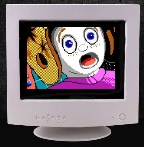
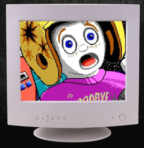
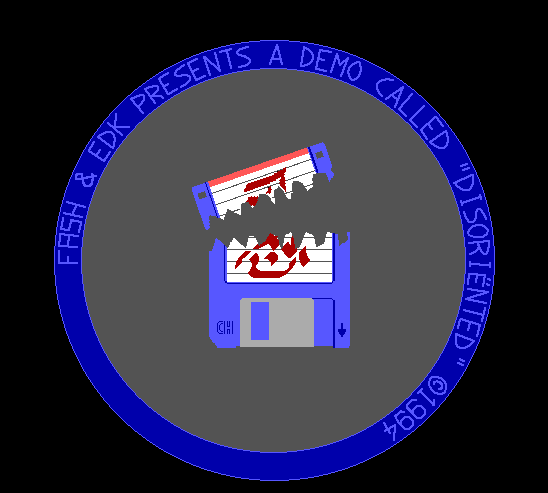
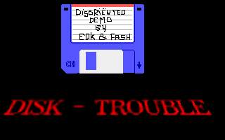
We made several demo’s like the one below. It must have been around 1994.
Dos emulator running our demo from 1994
Just after this one, we started a demo which could run from a 5.25″ boot disk. No dos operating system. When starting your pc, booting from a floppy you would get a starfield, with some text (from a bootsector) ,after that it would load the next sectors, wich contained the rest of the demo. Due to directly programming soundcard and graphics card, this was hard to pull off on different kinds of hardware.
Demo gfx
Example of assembly code for a effect.
    NAME plasma

.model small
.386
.data
colshades   db +001h, 001h,+001h
            db -001h,-001h,-000h
            db +000h,-000h,-001h
            db -000h,-000h,+000h
rgb_cols    db 256*3 dup (?)
cosptr dw 0
sinptr dw 30

.code
demo        proc near

show proc near
    xor di,di
    mov bp,200
show1:
    mov cx,320
    mov si,0
    mov dx,0
show0:
;    push ds
;    mov ax,7000h
;    mov ds,ax
;    lodsb
;    pop ds
    call getsincos
    add cosptr,1
    stosb
    loop show0
;    add dx,1
    add sinptr,1
    dec bp
    jnz show1
    ret
show endp

effect proc near
;   add cosptr,1
;    add sinptr,0
    ret
effect endp

getsincos proc near
    push di
    push ds
    mov si,cosptr
    mov di,sinptr
    mov ax,7000h
    mov ds,ax
    lodsb           ;get cos value
    cmp si,320      ;einde costab?
    jb cosok
    xor si,si
    lodsb
cosok:
    mov ah,al
    xchg si,di
    lodsb           ;get cos value
    cmp si,320      ;einde costab?
    jb sinok
    xor si,si
    lodsb
sinok:
    xchg si,di
    pop ds
    mov cosptr,si
    mov sinptr,di

    mov dx,0
    mov dl,al
    add dl,ah
    adc dh,0
    shr dx,1
    mov al,dl
;    xor al,ah
;    add al,ah
    pop di
    ret
getsincos endp

setcols proc near
    push    es
    push    ds
    pop     es
    mov     di,offset rgb_cols
    mov     si,offset colshades
    mov     dl,0    ;start with black
    mov     bh,0
    mov     bl,0
    mov     bp,4
set_rgball:
    mov     cx,64-1
set_rgb:
    mov     al,dl
    stosb
    mov     al,bh
    stosb
    mov     al,bl
    stosb
    mov     al,[si]
    add     dl,al
    mov     al,[si+1]
    add     bh,al
    mov     al,[si+2]
    add     bl,al
    loop    set_rgb
    add     si,3
    dec     bp
    jnz     set_rgball
    pop     es
    ret
setcols endp

setrgb proc near
    mov dx,3c8h
    xor al,al       ;start with colour 00h
    out dx,al
    inc dx
    mov si,offset rgb_cols
    mov cx,256*3
    rep outsb       ;set 256 RGB values
    ret
setrgb endp

wvtr proc near
    mov dx,3dah
wtv:
    in al,dx
    test al,8
    jz wtv
    ret
wvtr endp

start:
    cld
    mov ax,@data
    mov ds,ax
    mov ax,0a000h
    mov es,ax
    mov ax,13h
    int 10h         ;screen 320x200 256 colours
    call setcols
    call setrgb
    call show
    mov al,11111101b
    out 21h,al      ;disable int
mloop:
    call wvtr
;    call show
    call effect
    mov ah,1
    int 16h
    jz mloop
    xor ah,ah
    int 16h
exit:
    xor al,al
    out 21h,al      ;enable int
    mov ax,3
    int 10h         ;screen  80x25 text
    mov ax,4c00h
    int 21h         ;back to DOS
demo        endp

end start
"If something is worth doing, it's worth overdoing."