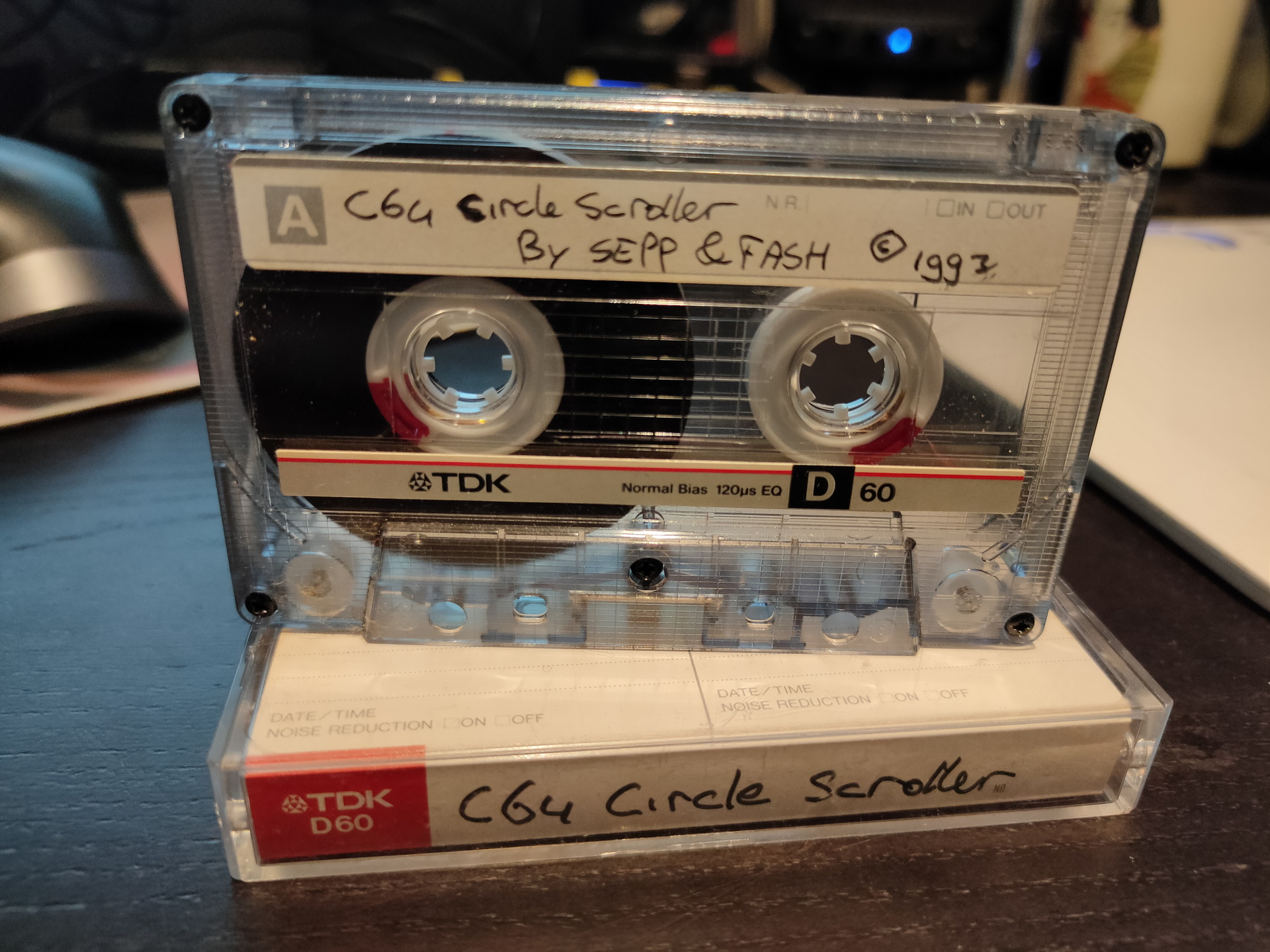
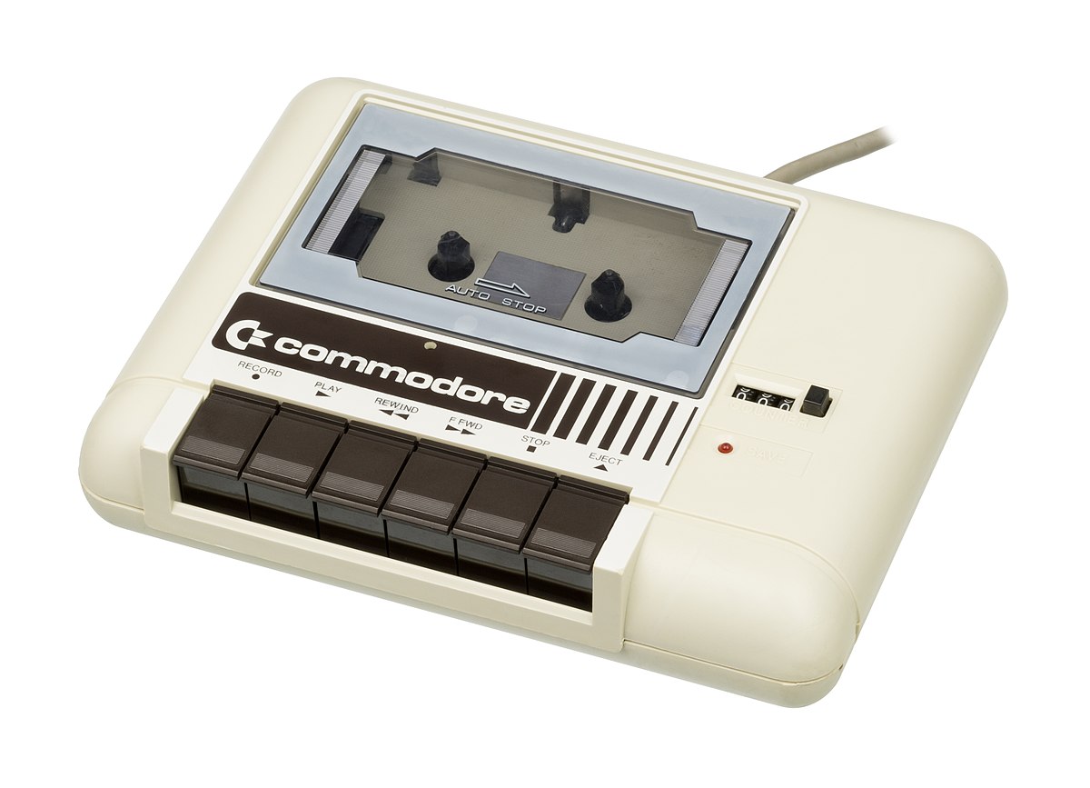
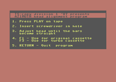
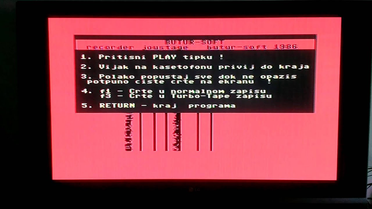
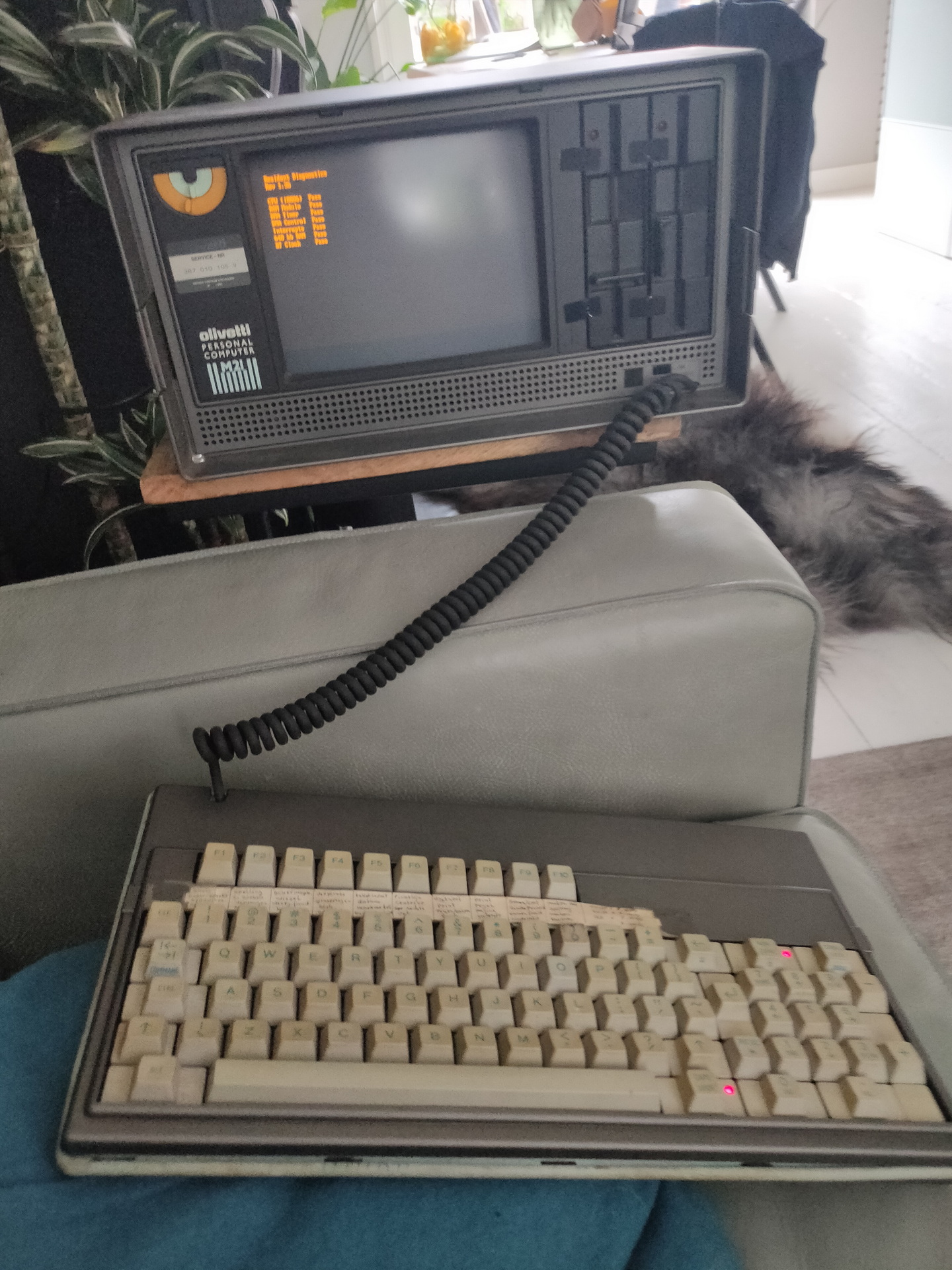
Recently back to old skool retro!
As posted https://www.henriaanstoot.nl/2022/05/03/c64-and-sd2iec/
Wellll, i bought some goodies from gotek.nl
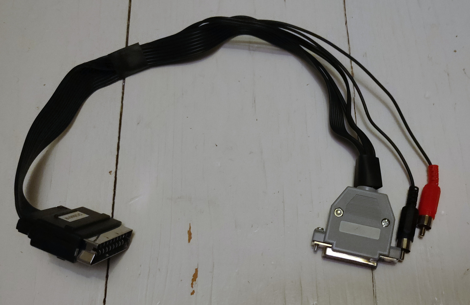
A new SUB-D(23) to scart video cable for amiga.
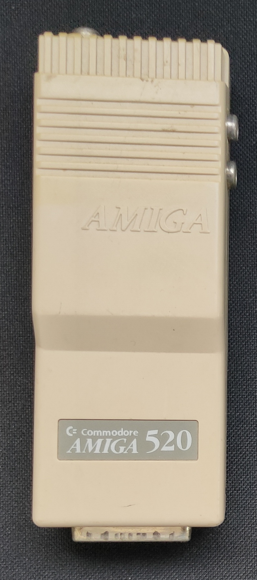
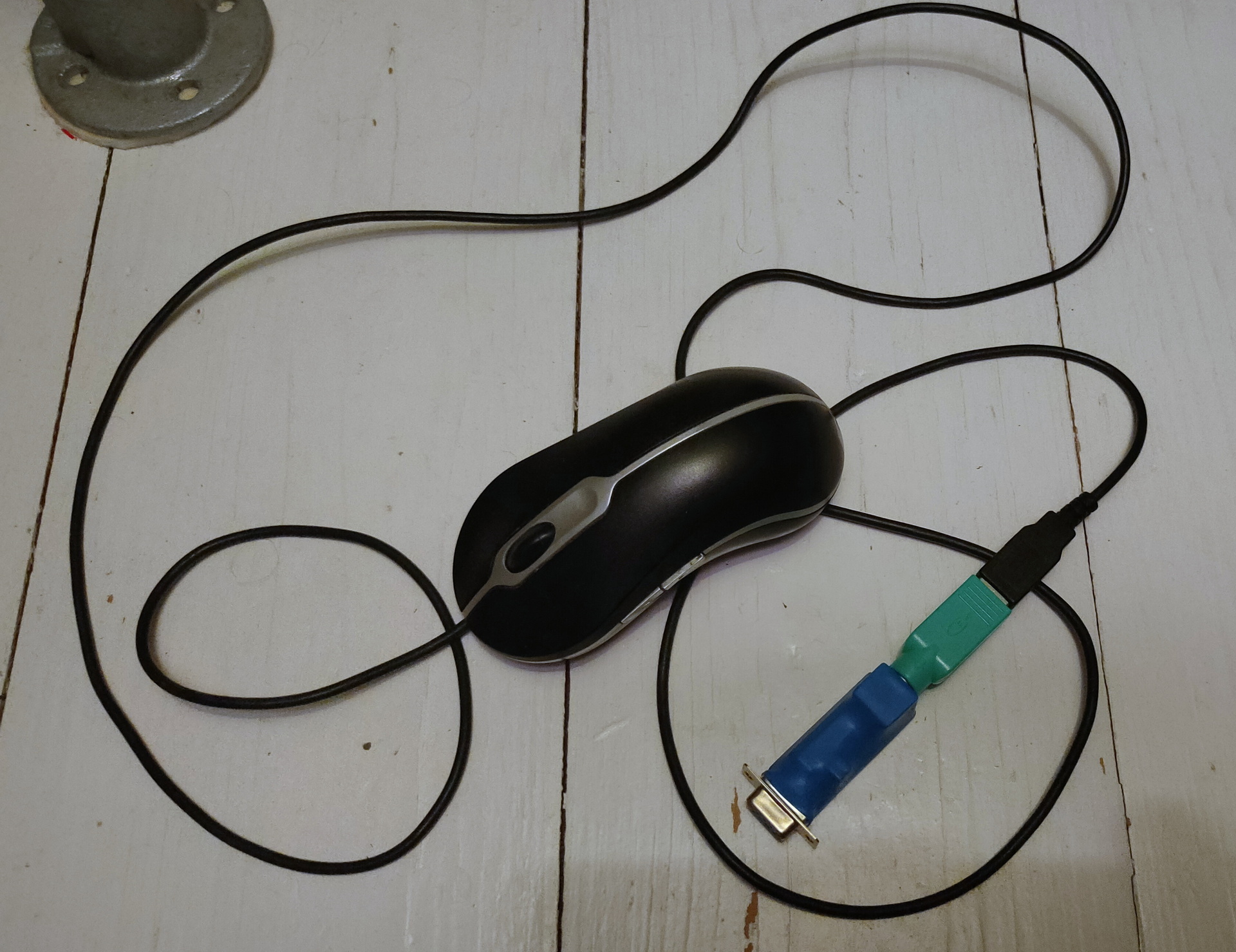
A 9pindin mouse to PS/2 convertor
A switchless (using key combination) diskdrive switcher df0<>df1
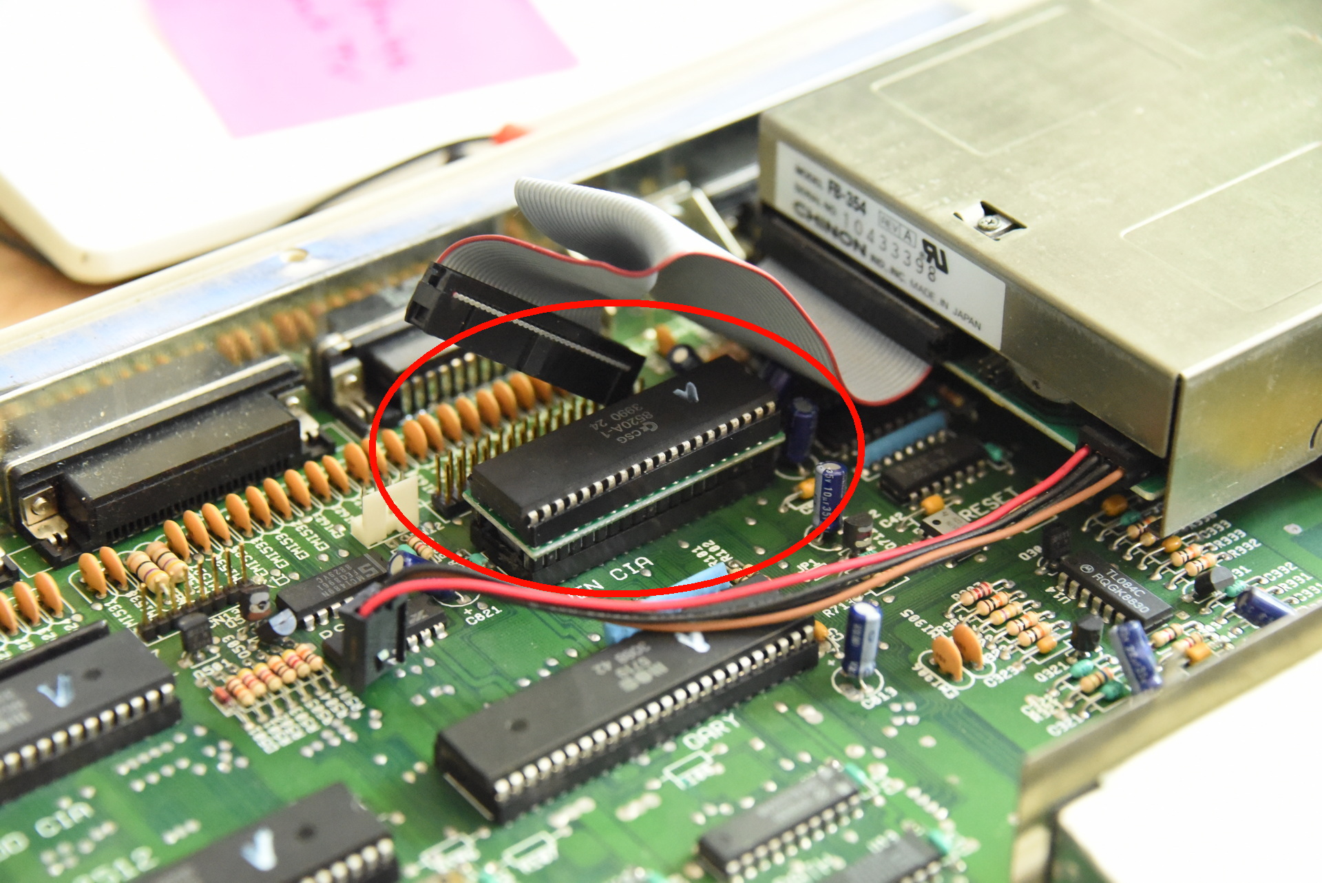
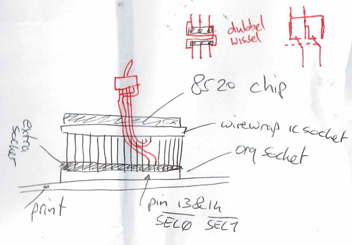
I used to make a floppy switch myself in the past, i used a wirewrap socket, and a cross switch. Made a hole in the back, with the little switch.
This one does not need a hole in your case for the switch.
Gotek Floppydrive Emulator with Rotary Encoder
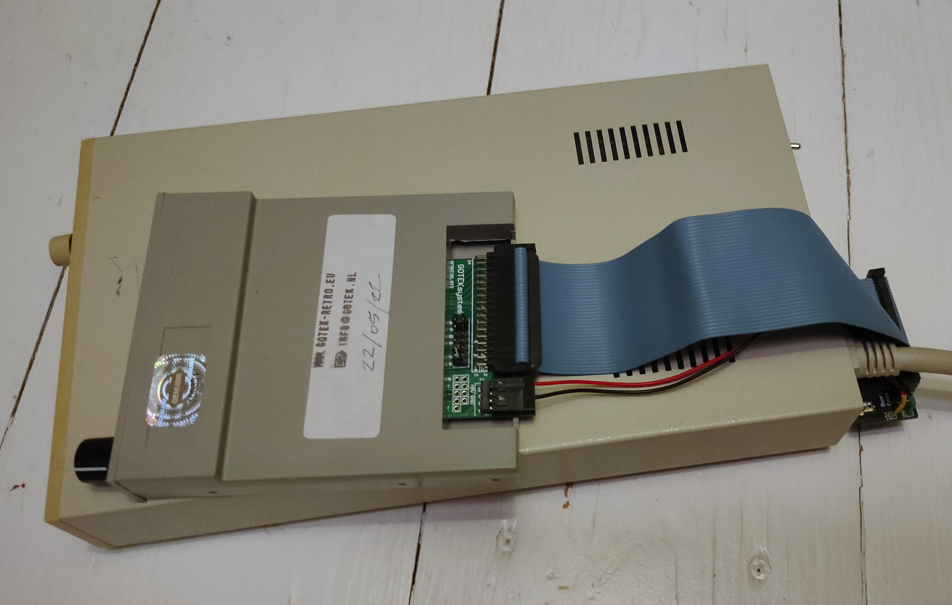
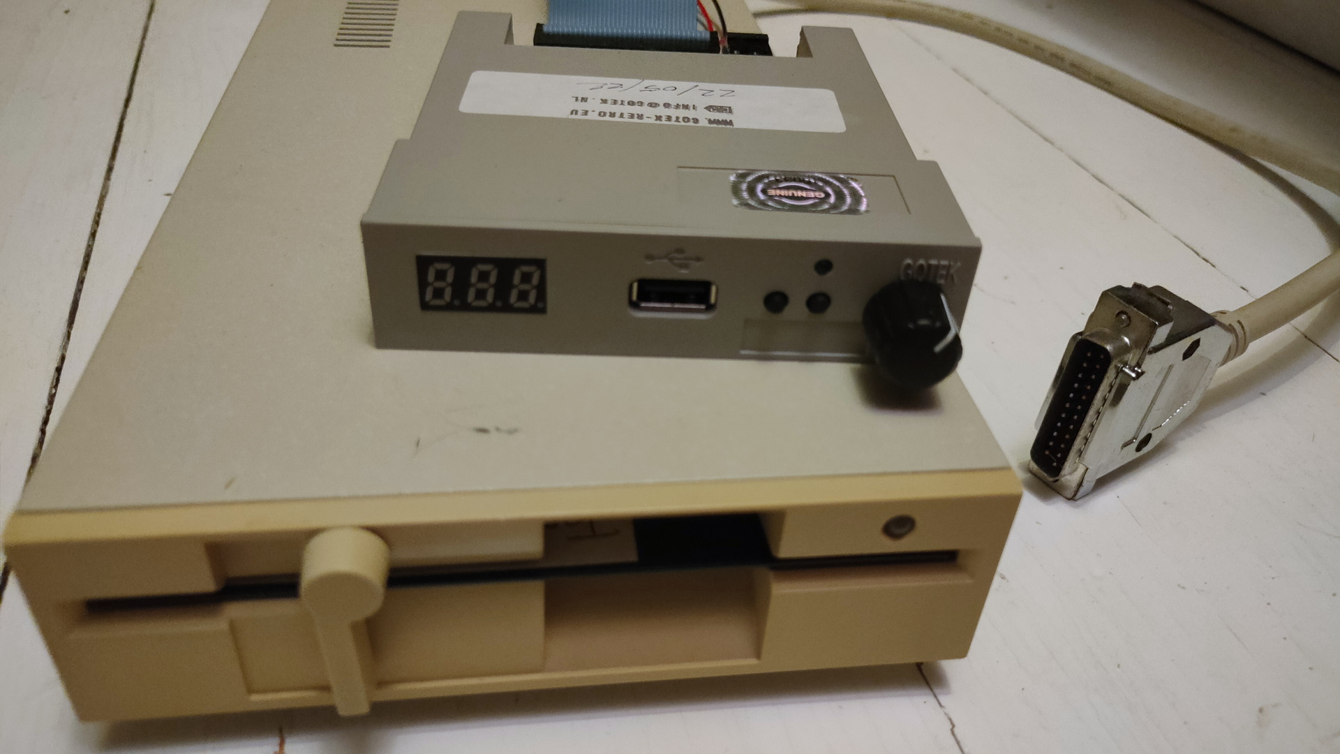
This drive supports a lot of disk formats and systems, i will have to look into that ..
https://github.com/keirf/FlashFloppy/wiki/Host-Platforms