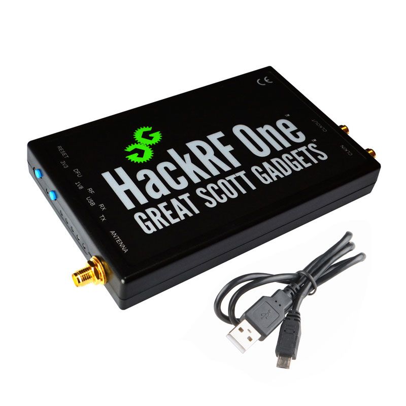
HackRF One from Great Scott Gadgets is a Software Defined Radio peripheral capable of transmission or reception of radio signals from 1 MHz to 6 GHz. Designed to enable test and development of modern and next generation radio technologies, HackRF One is an open source hardware platform that can be used as a USB peripheral or programmed for stand-alone operation.
1 MHz to 6 GHz operating frequency
half-duplex transceiver
up to 20 million samples per second
8-bit quadrature samples (8-bit I and 8-bit Q)
compatible with GNU Radio, SDR#, and more
software-configurable RX and TX gain and baseband filter
software-controlled antenna port power (50 mA at 3.3 V)
SMA female antenna connector
SMA female clock input and output for synchronization
convenient buttons for programming
internal pin headers for expansion
Hi-Speed USB 2.0
USB-powered
open source hardware
I’ve got dvb alternative below now. Hackrf cannot be bought anymore
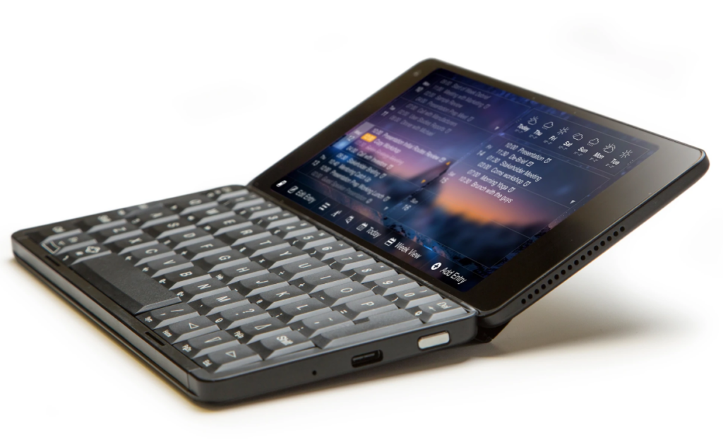
Gemini PDA
Android / Linux PDA
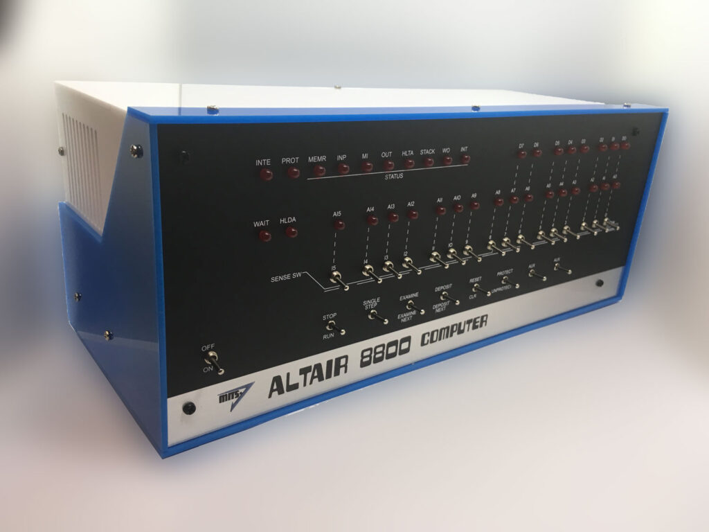
ALTAIR 8800 EMULATOR KIT
The Altair 8800 is a microcomputer designed in 1974 and based on the intel 8080 CPU. Using only switches to program and leds for output. Even my DIY build computer has a hex keyboard input and 7segments display.
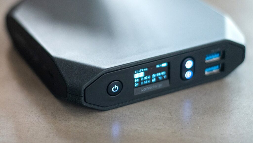
Omnicharge 20+ Usb C Wireless Power Bank 20,000mAh Power Delivery 3.0 + Quick Charge 3.0
You can use this as a mobile soldering station using a TS100 soldering iron.
HAVE IT
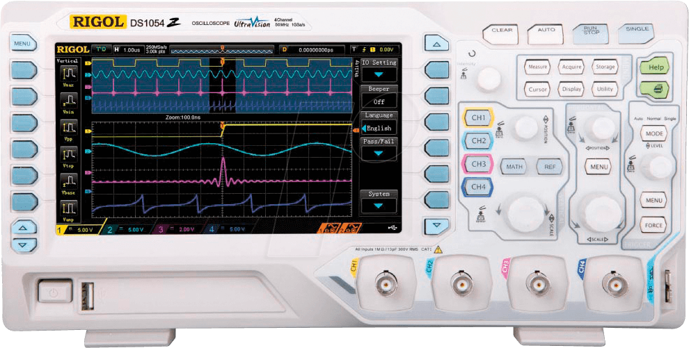
Rigol Oscilloscope DS1054
HAVE Z VERSION (LOGIC ANALIZER)
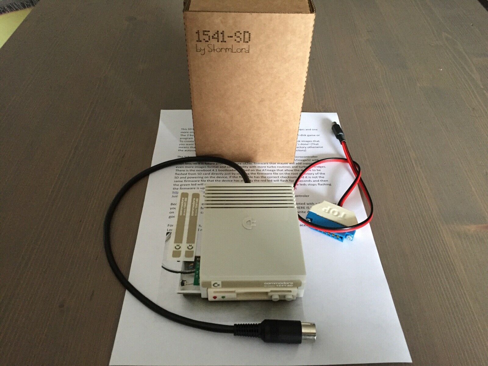
SDCard reader for C64 and other commodore machines
Got this one now, superb. And a Meatloaf DIY
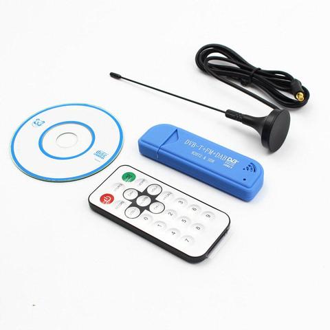
Tv Stick Dab Fm Dvb-t RTL2832 R820T Sdr RTL-SDR Dongle Stick Digitale Tv Tuner Ontvanger TVSDVBS816
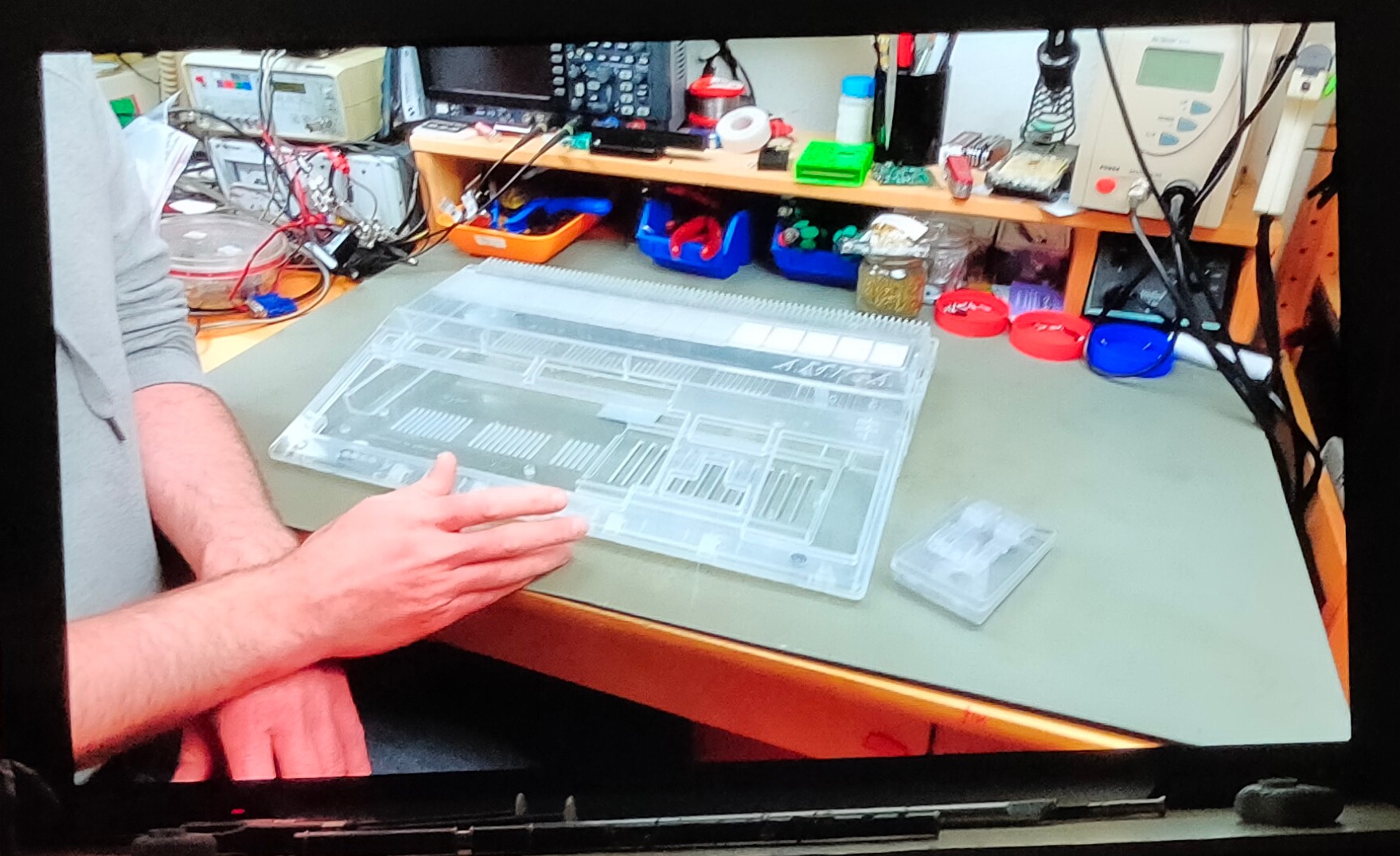
Modded this one, as part of my modular amiga system where i wanted to remake every part onto 10×15 euro prints. So i could swap things out for other boards.
Memory expansion
512k .. missing in action Go a new one in … ?
Boot selector
Swaps df0 and df1 DIY version was a wirewrap ic socket with a cross switch, now i have a Gotek buffered switching module with can be actvated with a keystroke. (Gotek post)
Keyboard mod
Hidden key (in the space of the stands, which triggered a extra key stroke)
Kickstart selector
A print you can insert in the ROM socket of your amiga. Had only 1.2 and 1.3. Now there are many .. like diagnostic roms. I made a altered 1.2 version .. which was unusable .. i f*cked it up
SID mod
Added a sid parallel on the 8020 CIA chip
Gotek driver emulator
I made a arduino version to read disks. (Other post) But this is a disk image drive emulator. See Gotek post
Boot sector warn
Piezo beeper which warned me when a boot sector was being written (virus alert)
Sound filter fix
Amiga audio filter enhancer, using capacitors and resistors
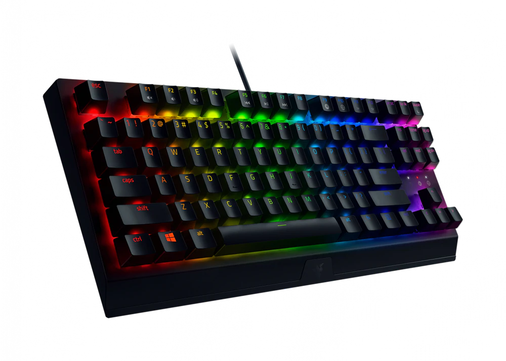
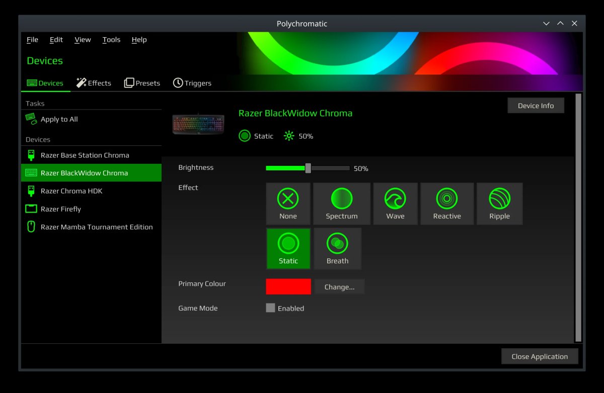
A fancy keyboard….. At last a clickety keyboard. A Razer Blackwidow V3 mechanical keyboard. I’m not a gamer, but i like the clickety sounds. RGB leds are always nice to play with.
One of the nice things about razer is the Linux support!
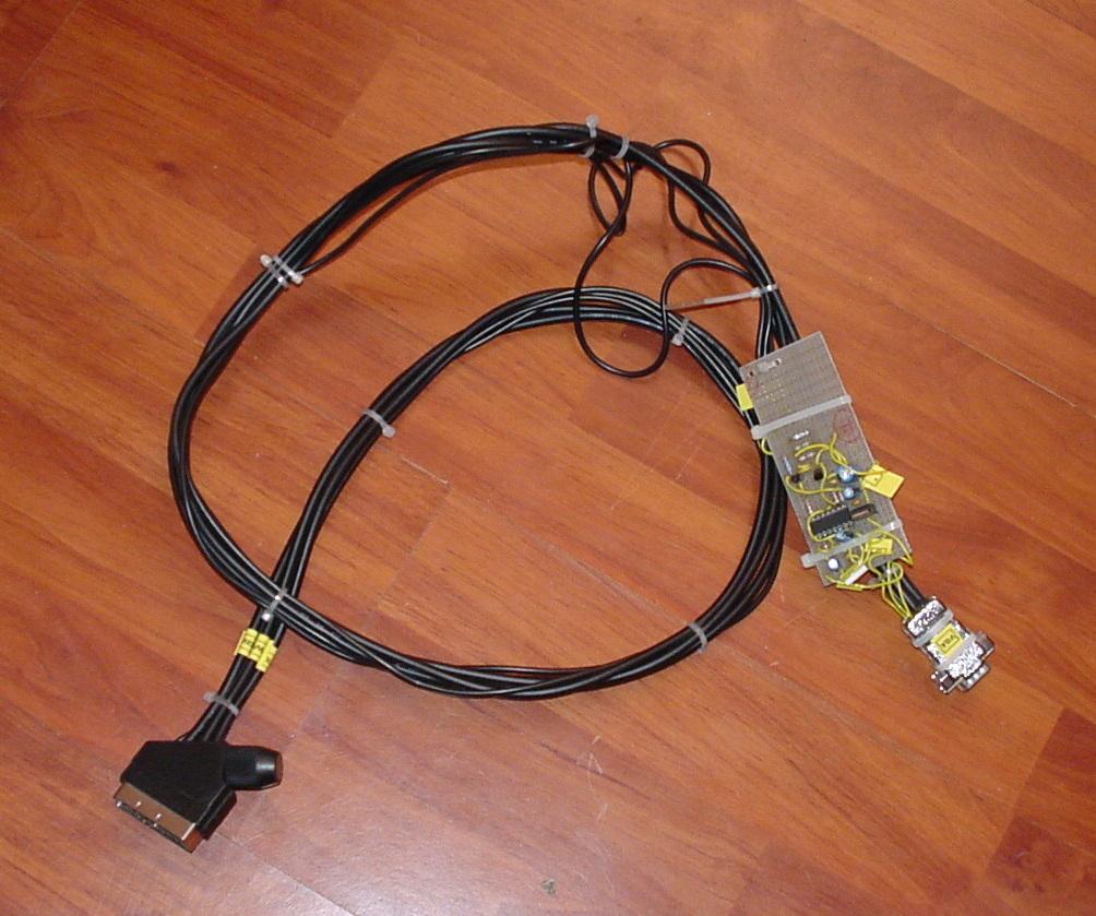
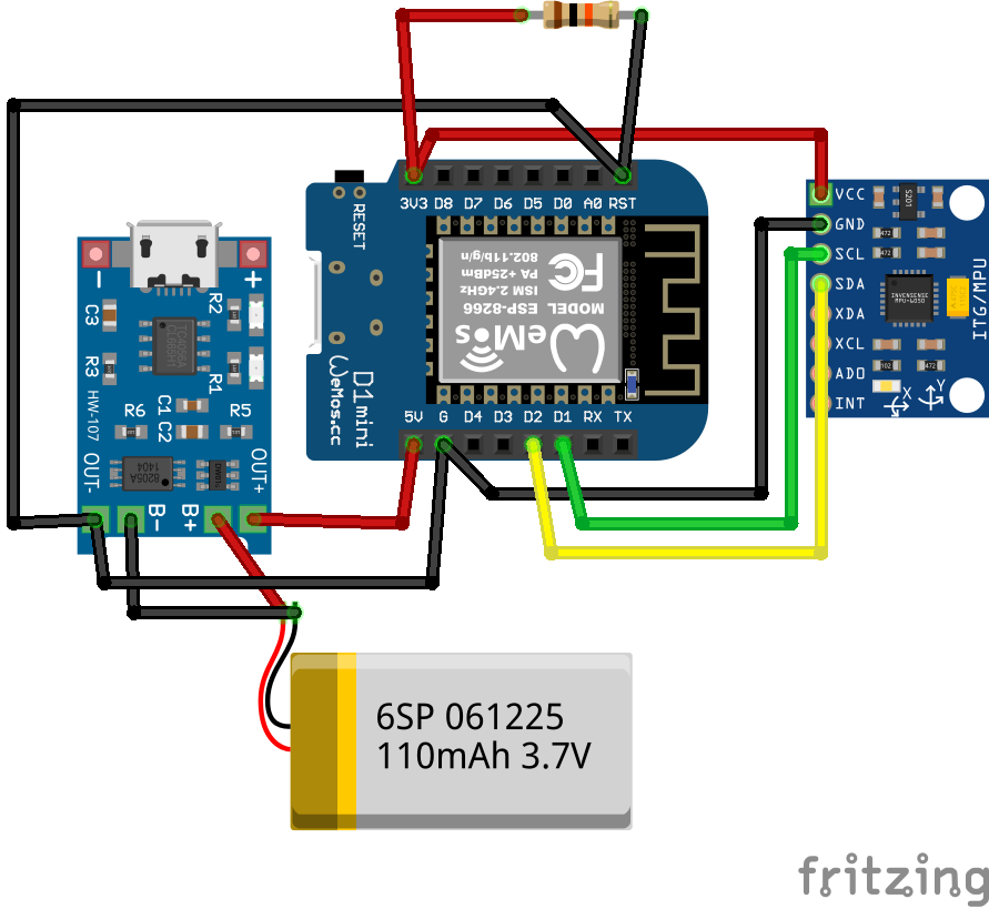
Put the box flat on the table to switch off. When you put it on one side, it will controll your lights brightness. 20,40,60,80 and 100%, just by rotating and putting it down on its sides.
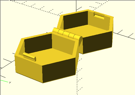
3D printed case
Schematics (without the wireless charging part)
Wireless part
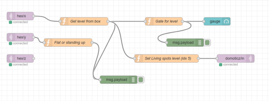
Node-Red Controll part (source below)
Nice to have’s : Arduino-sleep mode, wakeup with a movement sensor.
Arduino Code
#include <Wire.h>
//#include <SPI.h>
#include <PubSubClient.h>
//#include <string.h>
//#include <stdio.h>
#include <ESP8266WiFi.h>

// Wifi settings
const char* ssid = "xxxxxx";
const char* password = "xxxxxxxxxx";
const char* mqtt_server = "10.1.0.17";

// I2C address of the MPU-6050 - 0x68 or 0x69 if AD0 is pulled HIGH
const int MPU = 0x68;
int16_t AcX, AcY, AcZ, GyX, GyY, GyZ;
float gForceX, gForceY, gForceZ, rotX, rotY, rotZ;

// Wifi MAC address
byte mac[]= {  0xDE, 0xED, 0xBA, 0xFE, 0xFE, 0xED };

WiFiClient espClient;
IPAddress ip;
PubSubClient mqttClient(espClient);

// IP address of your MQTT server
const char* server = "10.1.0.17";
//const char* outTopic = "test/";
//const char* server = "iot.eclipse.org";

void dataReceiver(){
  Wire.beginTransmission(MPU);
  Wire.write(0x3B);  // starting with register 0x3B (ACCEL_XOUT_H)
  Wire.endTransmission(false);
  Wire.requestFrom(MPU,14,true);  // request a total of 14 registers
  AcX = Wire.read()<<8|Wire.read();  // 0x3B (ACCEL_XOUT_H) & 0x3C (ACCEL_XOUT_L)
  AcY = Wire.read()<<8|Wire.read();  // 0x3D (ACCEL_YOUT_H) & 0x3E (ACCEL_YOUT_L)
  AcZ = Wire.read()<<8|Wire.read();  // 0x3F (ACCEL_ZOUT_H) & 0x40 (ACCEL_ZOUT_L)
  GyX = Wire.read()<<8|Wire.read();  // 0x43 (GYRO_XOUT_H) & 0x44 (GYRO_XOUT_L)
  GyY = Wire.read()<<8|Wire.read();  // 0x45 (GYRO_YOUT_H) & 0x46 (GYRO_YOUT_L)
  GyZ = Wire.read()<<8|Wire.read();  // 0x47 (GYRO_ZOUT_H) & 0x48 (GYRO_ZOUT_L)
  processData();
}

void processData(){
  gForceX = AcX / 16384.0;
  gForceY = AcY / 16384.0;
  gForceZ = AcZ / 16384.0;

  rotX = GyX / 131.0;
  rotY = GyY / 131.0;
  rotZ = GyZ / 131.0;
}

void debugFunction(int16_t AcX, int16_t AcY, int16_t AcZ, int16_t GyX, int16_t GyY, int16_t GyZ){
  // Print the MPU values to the serial monitor
  Serial.print("Accelerometer: ");
  Serial.print("X="); Serial.print(gForceX);
  Serial.print("|Y="); Serial.print(gForceY);
  Serial.print("|Z="); Serial.println(gForceZ);
  Serial.print("Gyroscope:");
  Serial.print("X="); Serial.print(rotX);
  Serial.print("|Y="); Serial.print(rotY);
  Serial.print("|Z="); Serial.println(rotZ);
}

void reconnect() {
  // Loop until we're reconnected
  while (!mqttClient.connected()) {
    Serial.print("Attempting MQTT connection...");
    // Attempt to connect
    if (mqttClient.connect("arduinoClient")){
      Serial.println("connected");
    }
    else {
      Serial.print("failed, rc=");
      Serial.print(mqttClient.state());
      Serial.println(" try again in 5 seconds");
//      Wait 5 seconds before retrying
      delay(1000);
    }
  }
}

void setup(){
  Serial.begin(9600);

    setup_wifi();

  Wire.begin(0,2);
  Wire.beginTransmission(MPU);
  Wire.write(0x6B);  // PWR_MGMT_1 register
  Wire.write(0);     // set to zero (wakes up the MPU-6050)
  Wire.endTransmission(true);

  mqttClient.setServer(server, 1883);

//  Ethernet.begin(mac);
//  ip = Ethernet.localIP();

  Serial.println(ip);
  Serial.println(server);
  //delay(1500);
}

char* init(float val){

  char buff[100];

  for (int i = 0; i < 100; i++) {
      dtostrf(val, 4, 2, buff);  //4 is mininum width, 6 is precision
  }
   return buff;

}

void setup_wifi() {

  delay(10);
  // We start by connecting to a WiFi network
  Serial.println();
  Serial.print("Connecting to ");
  Serial.println(ssid);

  WiFi.begin(ssid, password);

  while (WiFi.status() != WL_CONNECTED) {
    delay(500);
    Serial.print(".");
  }

  Serial.println("");
  Serial.println("WiFi connected");
  Serial.println("IP address: ");
  Serial.println(WiFi.localIP());
}

void dataAcc(){

  char mpu6050X[100]= "";
  strcat(mpu6050X,init(gForceX));

  char mpu6050Y[100]= "";
  strcat(mpu6050Y,init(gForceY));

  char mpu6050Z[100]= "";
  strcat(mpu6050Z,init(gForceZ));

  // accelerometer - "topic, mpu6050"
  mqttClient.publish("AcX/", mpu6050X);
  mqttClient.publish("AcY/", mpu6050Y);
  mqttClient.publish("AcZ/", mpu6050Z);
//  mqttClient.publish(outTopic, "text to send via mqtt");
}


void dataGy(){

  char mpu6050X[100]= "";
  strcat(mpu6050X,init(rotX));

  char mpu6050Y[100]= "";
  strcat(mpu6050Y,init(rotY));

  char mpu6050Z[100]= "";
  strcat(mpu6050Z,init(rotZ));

  // gyroscope - "topic, mpu6050"
  mqttClient.publish("GyX/", mpu6050X);
  mqttClient.publish("GyY/", mpu6050Y);
  mqttClient.publish("GyZ/", mpu6050Z);
//  mqttClient.publish(outTopic, "text to send via mqtt");
}

void loop(){
  dataReceiver();
  debugFunction(AcX,AcY,AcZ,GyX,GyY,GyZ);

  if (!mqttClient.connected()) {
    reconnect();
  }

  mqttClient.loop();

  dataAcc();
  dataGy();

  delay(2000);
}
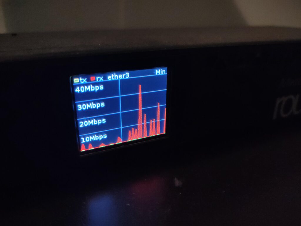
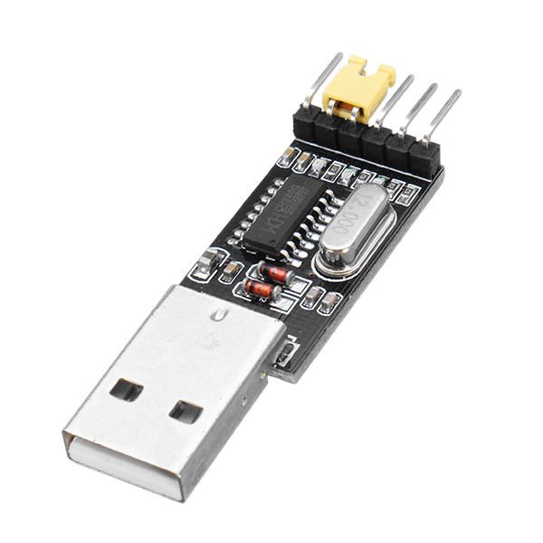
I’ve modded several LSC devices, most of them i could flash with esp-easy or tasmota. Why mod it? Because it uses the cloud .. i’d like to keep control myself. Just connect/solder a USB to TTL Converter UART Module like below. (See other posts)
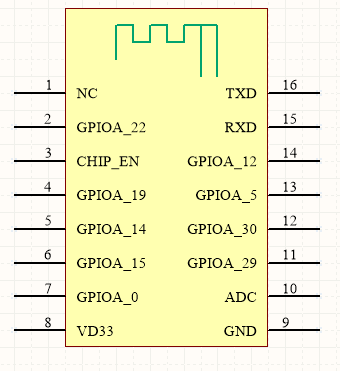
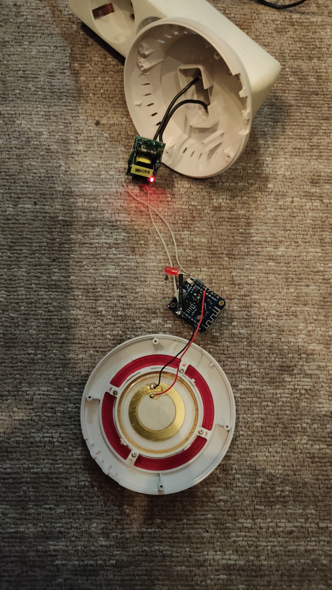
But this alarm was different, i ended up removing the chip and replace it with a ESP12.
Warning .. loud! .. Yes almost xmasA WR3 is almost like a ESP-12
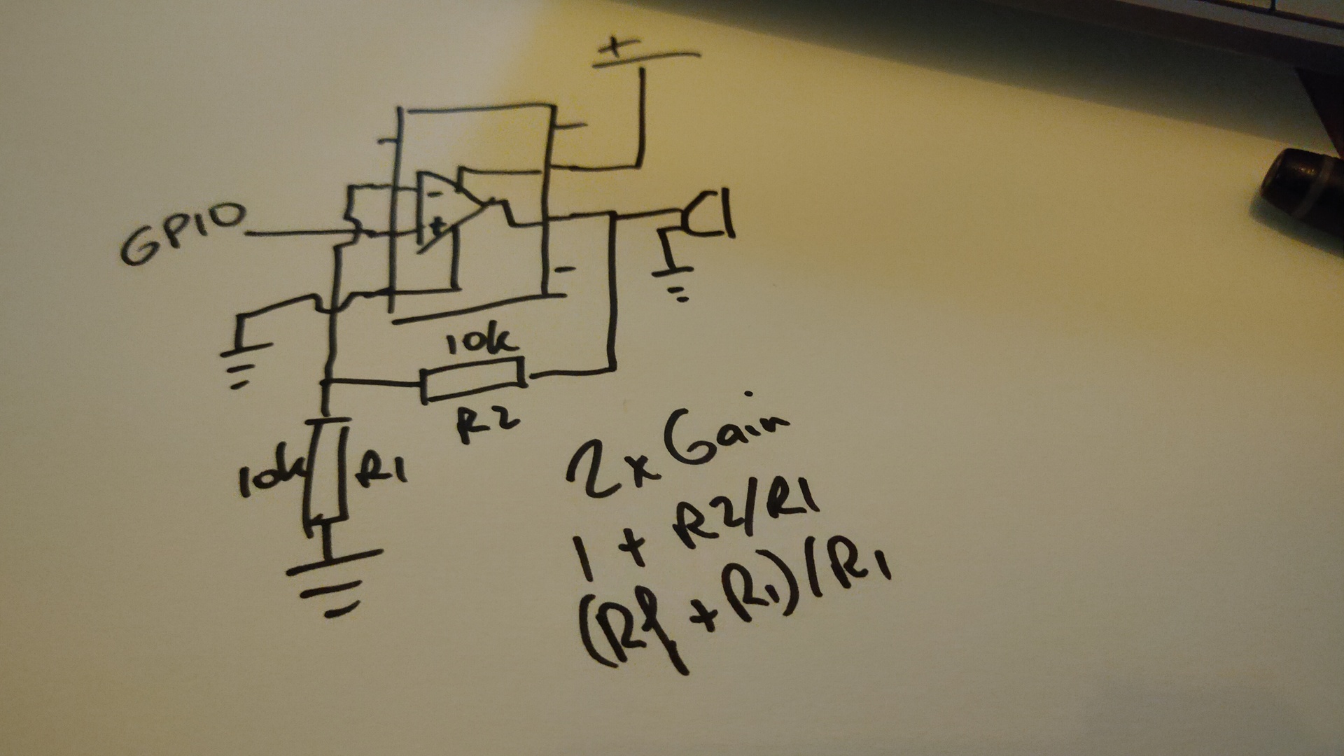
So now i had to figure out which GPIO pins and how to control them.
#1/bin/bash
# Flashed ESP Easy on this one
# When i did this, 2019, you needed version 2.1-beta1
# GPIO 4 controls LED
sleep 10
curl http://10.1.1.251/control?cmd=GPIO,4,1
sleep 1
curl http://10.1.1.251/control?cmd=GPIO,4,0
sleep 1
curl http://10.1.1.251/control?cmd=GPIO,4,1
sleep 2
curl http://10.1.1.251/control?cmd=GPIO,4,0
sleep 5
# Sending rtttl ringtone
curl "http://10.1.1.251/control?cmd=rtttl,5:d=4,o=5,b=112:8a,8a,a,8a,8a,a,8a,8c6,8f.,16g,2a,8a-,8a-,8a-.,16a-,8a-,8a,8a.,16a,8a,8g,8g,8a,g,c6"


alarm sound
 curl "http://10.1.1.251/control?cmd=rtttl,5:d=4,o=5,b=160:2g,2c6,2g,2c6,2g,2c6,2g,2c6"
pager
 curl "http://10.1.1.251/control?cmd=rtttl,5:d=4,o=5,b=160:8d6,16p,2d6,16p,8d6,16p,2d6,16p,8d6,16p,2d6"
Update 20221208 – removed internals
Removed my old hack and replaced it with a Wemos D1. Added a LED Next to do .. add a amplifier using a LM356/358
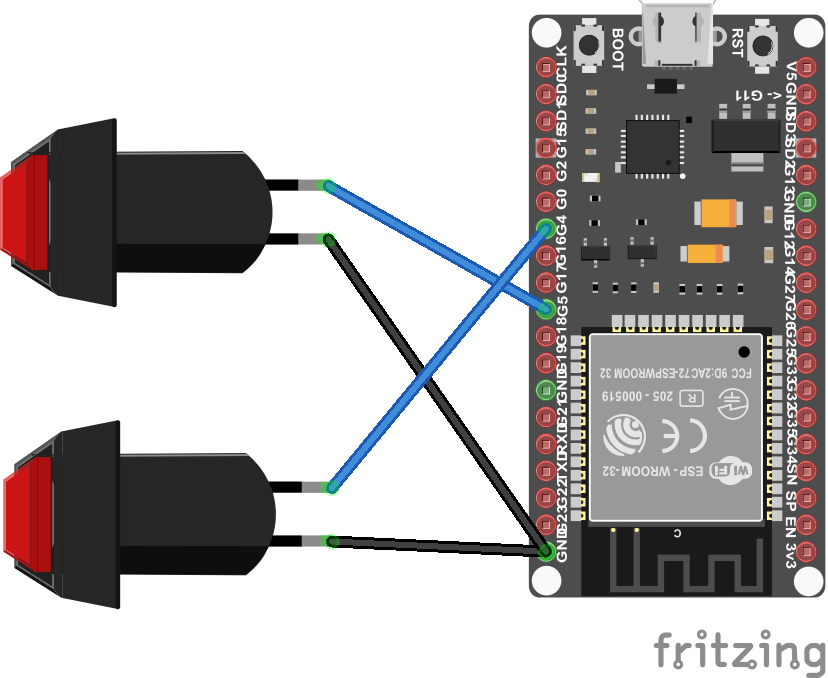
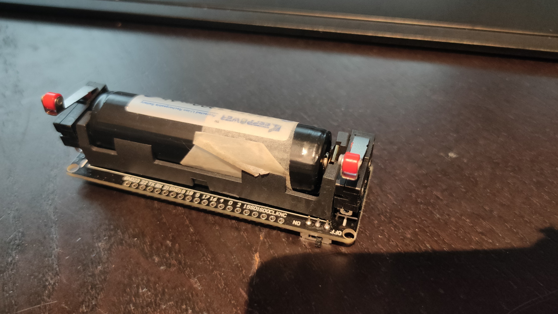
This was made using an Arduino and some buttons. I’m using Fbreader and Ebookdroid on the tablet.
Code:
Note: Volume buttons work for both apps, if you want to use other keys, you need to put a keymap.xml file in your fbreader books directory on your android device to remap those!