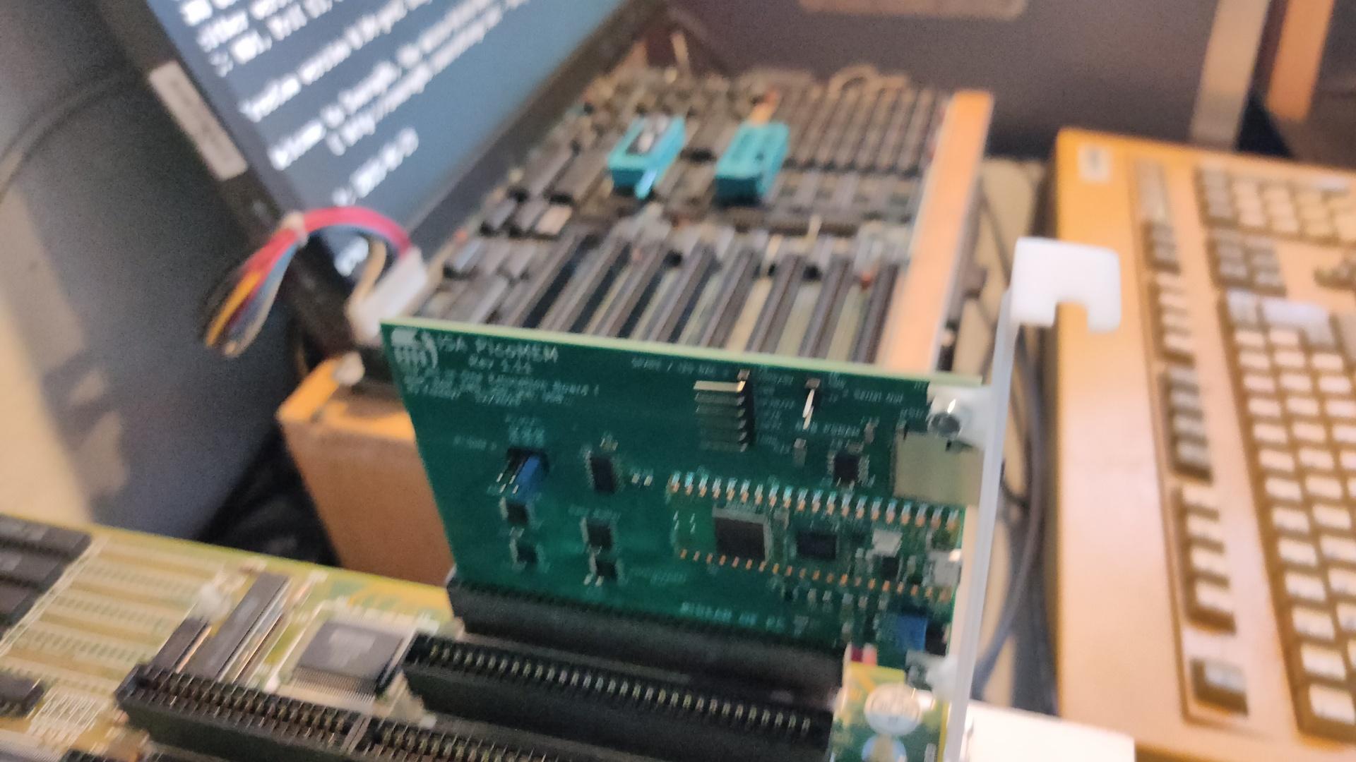
https://github.com/FreddyVRetro/ISA-PicoMEM
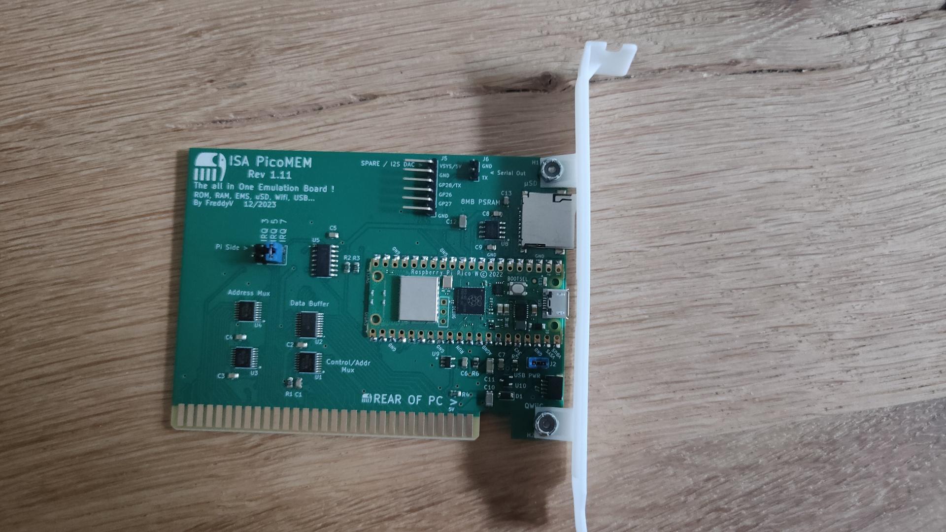
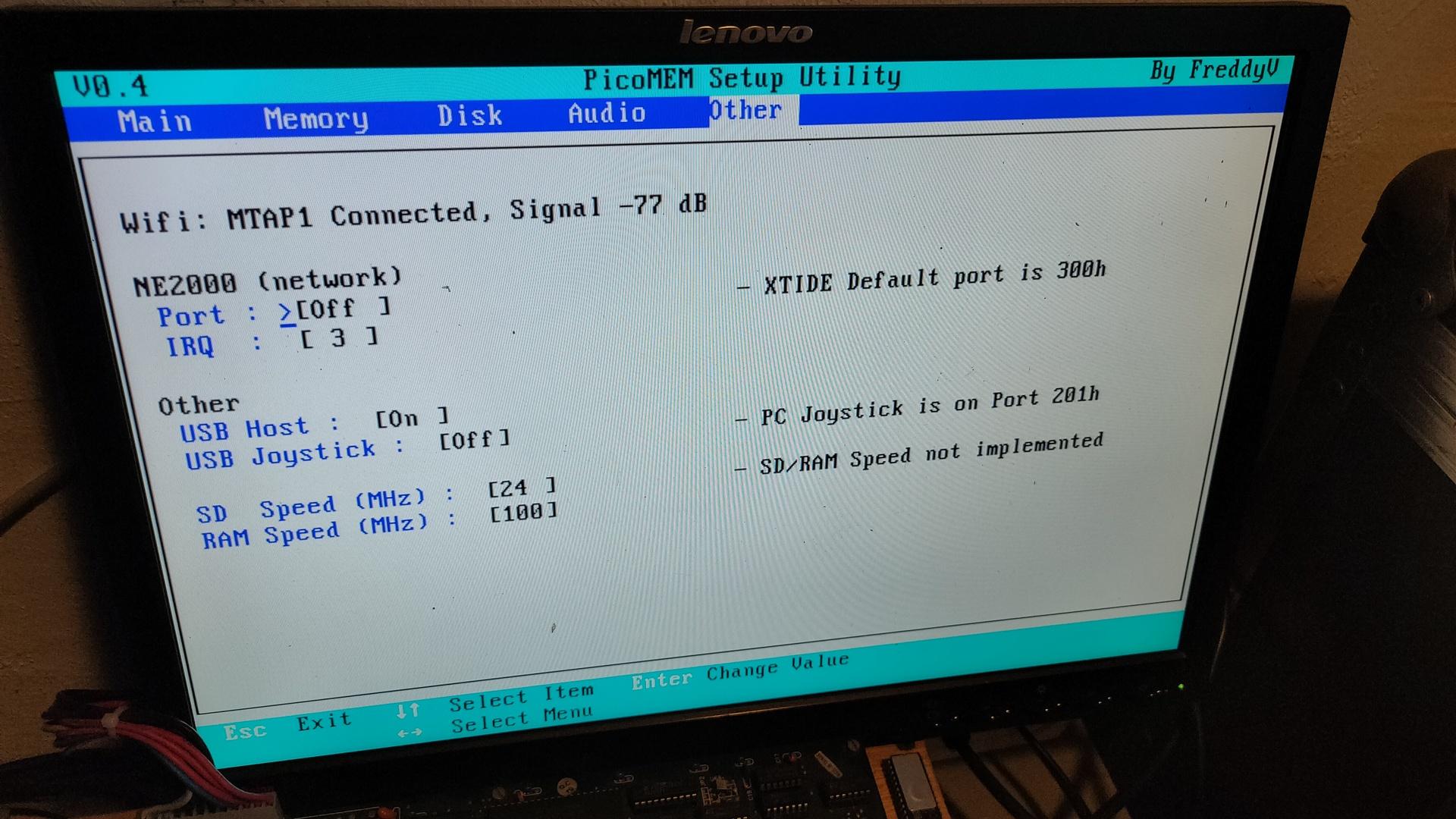
Awesome device
- Ram extender
- Soon Rom emulation
- Floppy and HDD emulation using images on microsd
- NE2000 network card over Wifi!!
- USB Mouse and Joystick
- Adlib
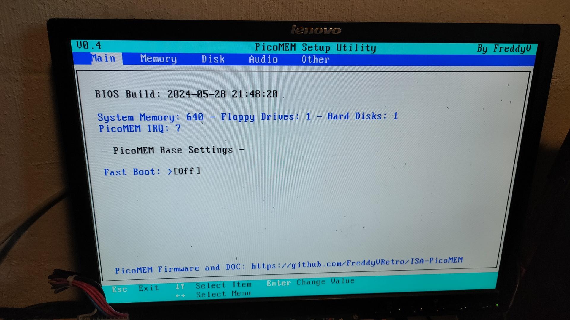
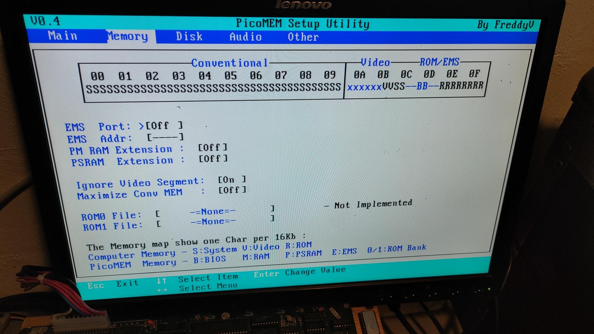
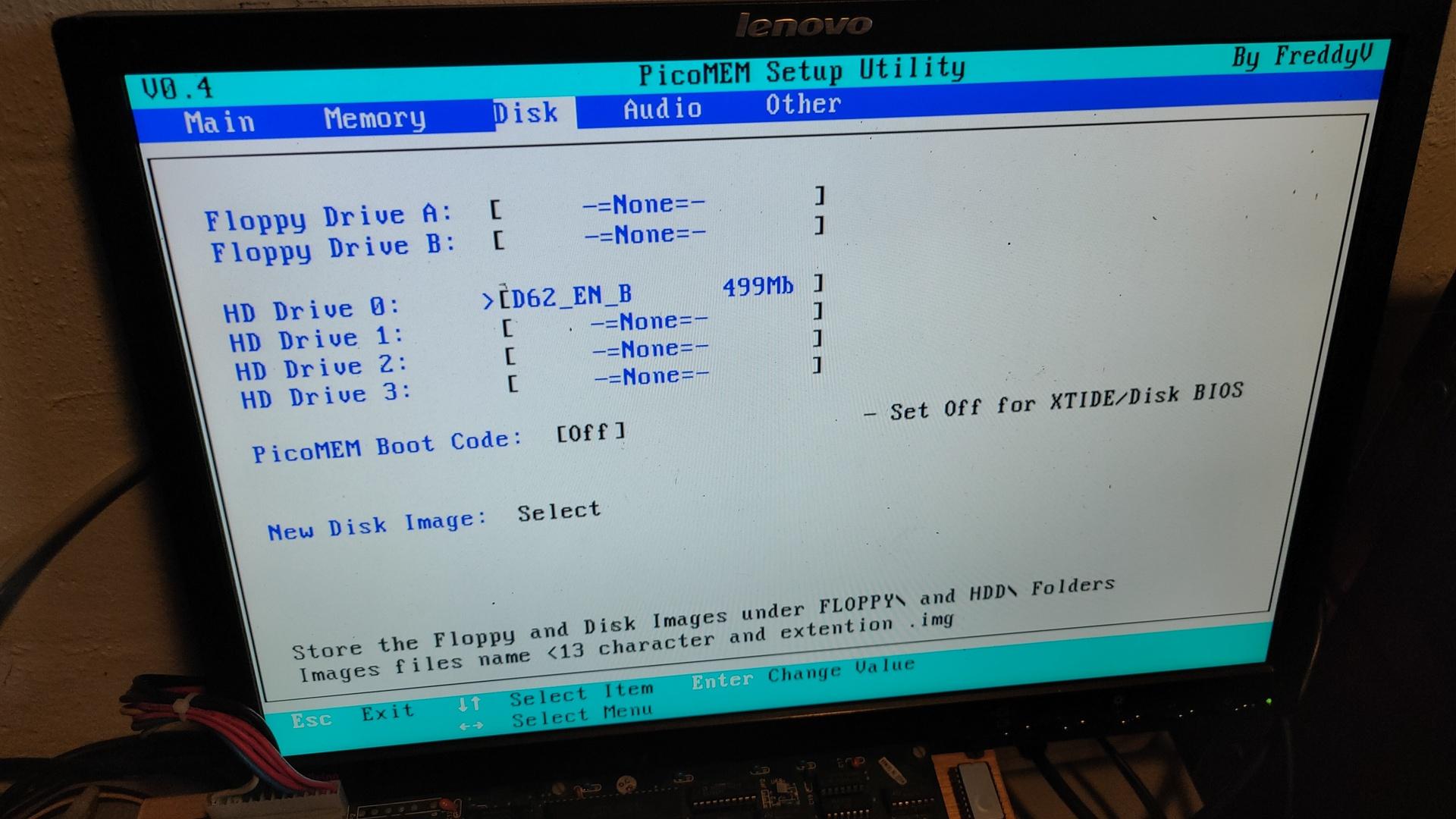
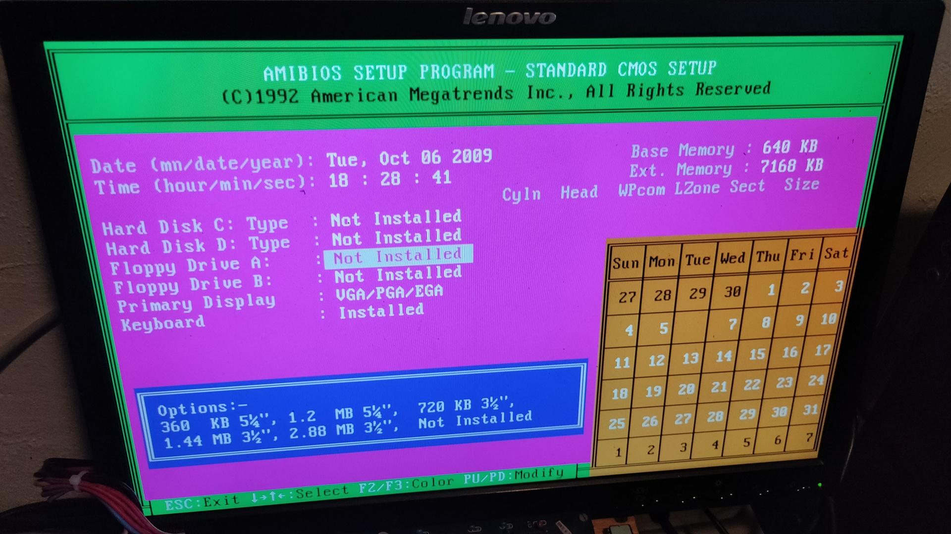
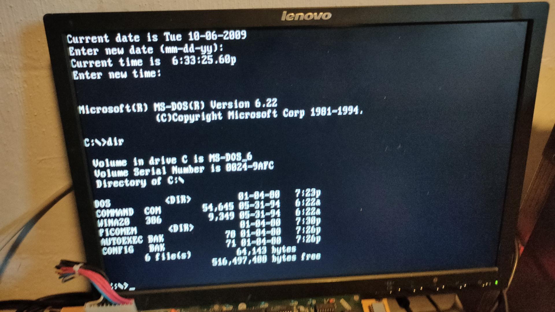
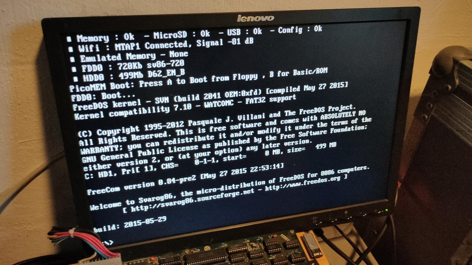
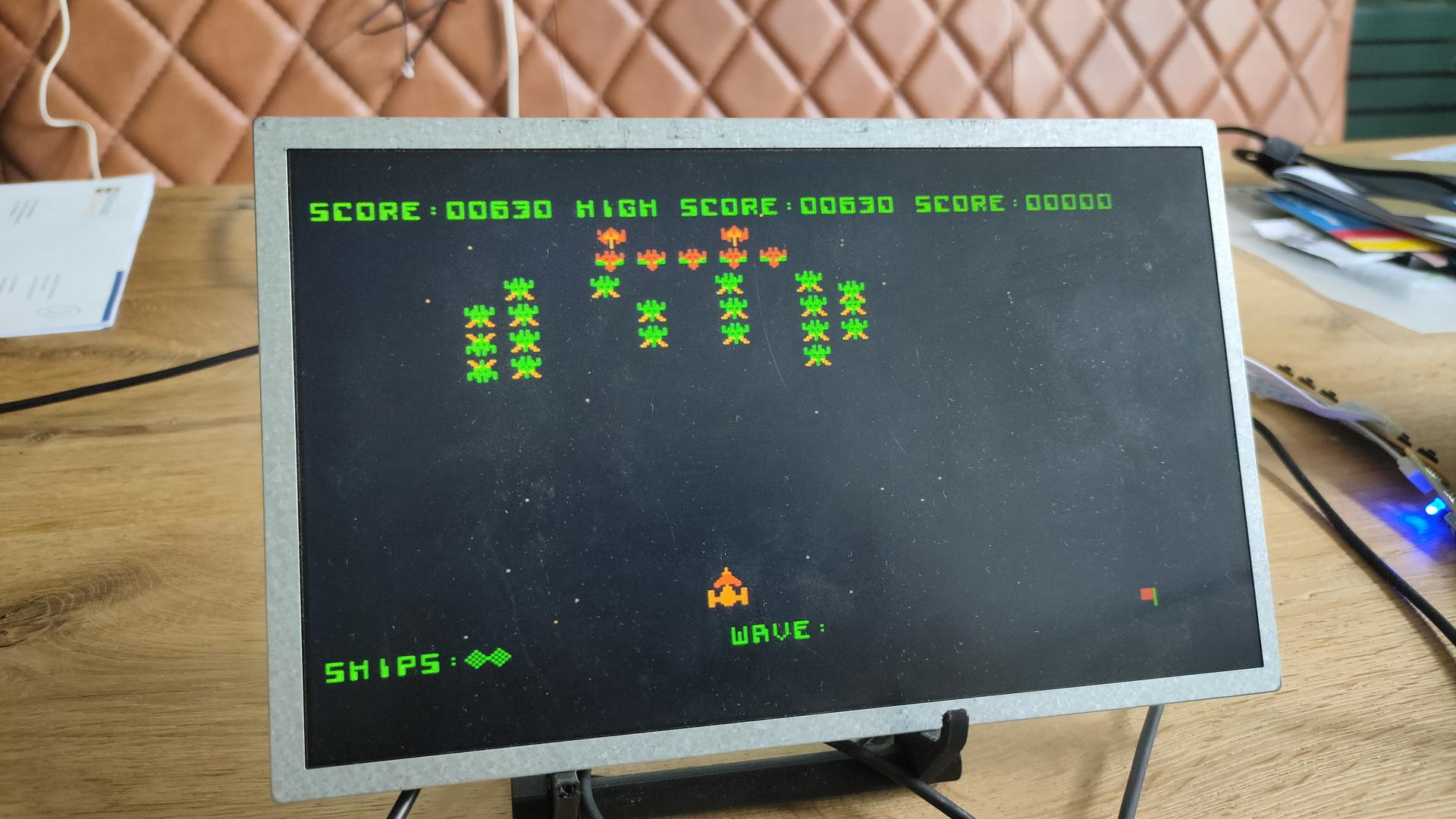
Some other screen captures
https://github.com/FreddyVRetro/ISA-PicoMEM
Awesome device
Some other screen captures
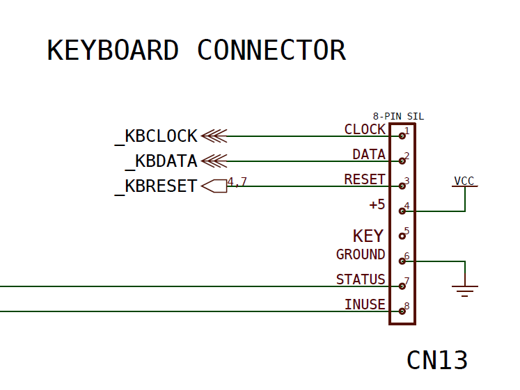
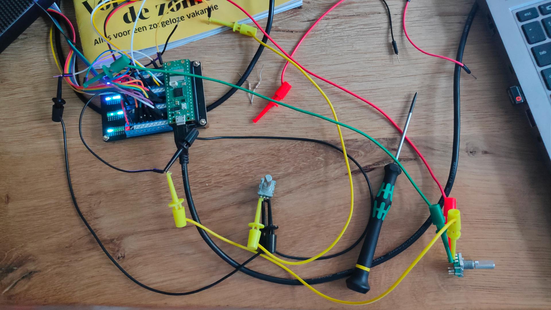
I’ve connected the rotary encoder directly to the zero.
Although many websites state that you need pull-up resistors, there is no need. Just use the internal pull-up resistors in the Pi.
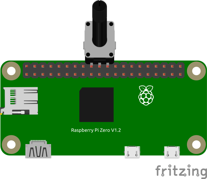
Example code
        GPIO.setmode(GPIO.BCM)					# Use BCM mode
        GPIO.setup(self.24, GPIO.IN, pull_up_down=GPIO.PUD_UP)
        GPIO.setup(self.25, GPIO.IN, pull_up_down=GPIO.PUD_UP)
NOTE: Between 24 and 25 is a GND connection
Besides USB HID below XT, C64 and Amiga connectors will be emulated
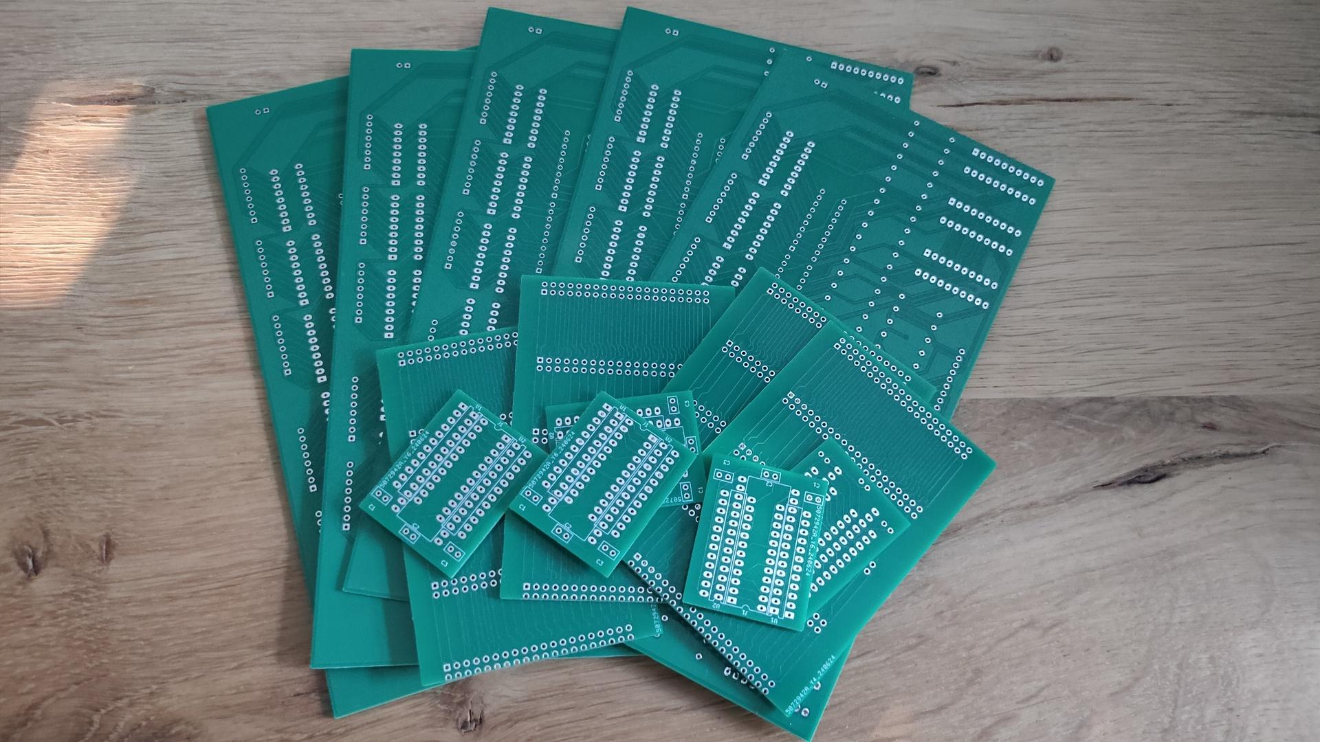
Got my new PCBs in.
My Bus Manipulator, Backplane for 6502, and C64 PLA replacement.
I’m selling the leftover PCBs if you are interested.
These are not the final versions.
They should work, but they lack holes for stand-offs or feet.
Example setups for the backplane.
Using a flatcable or direct connection to my 6502 SBC.
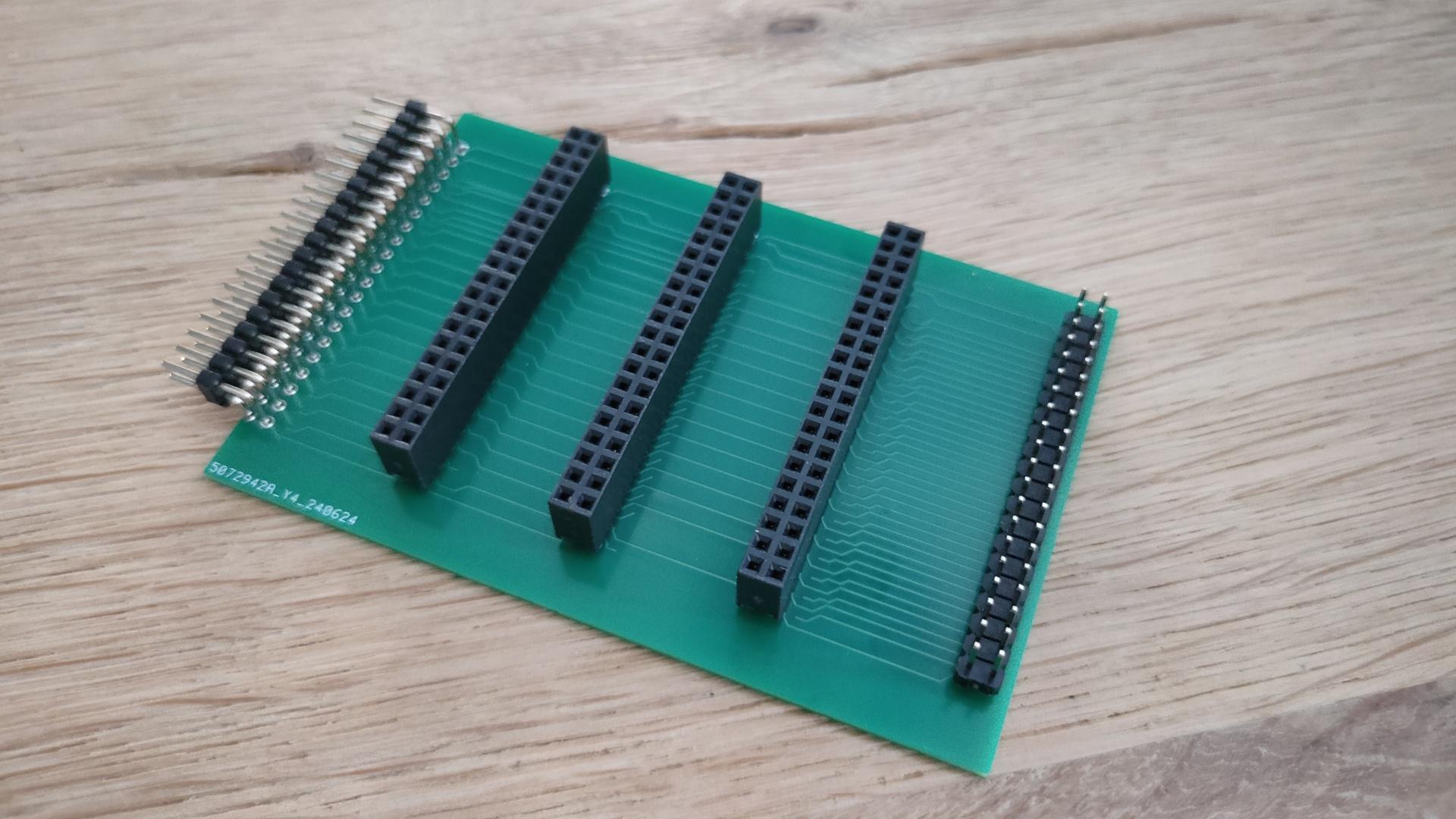
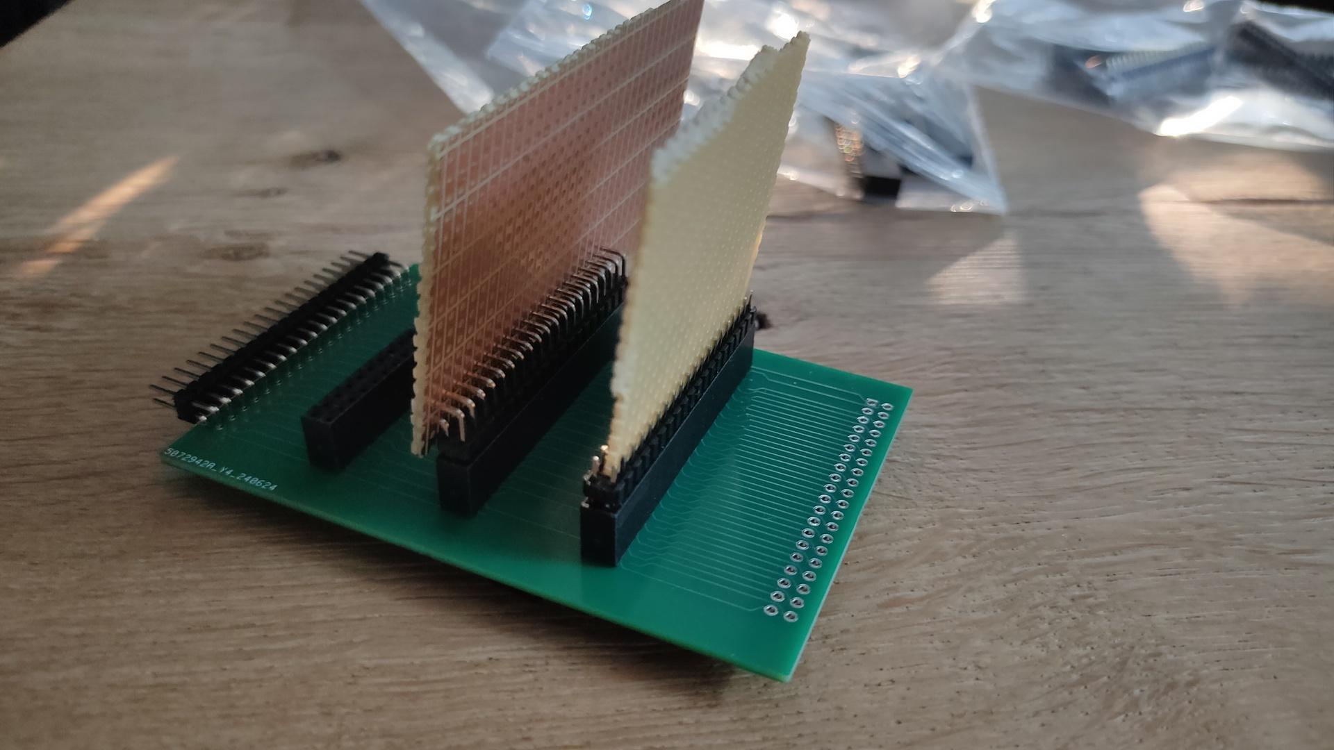
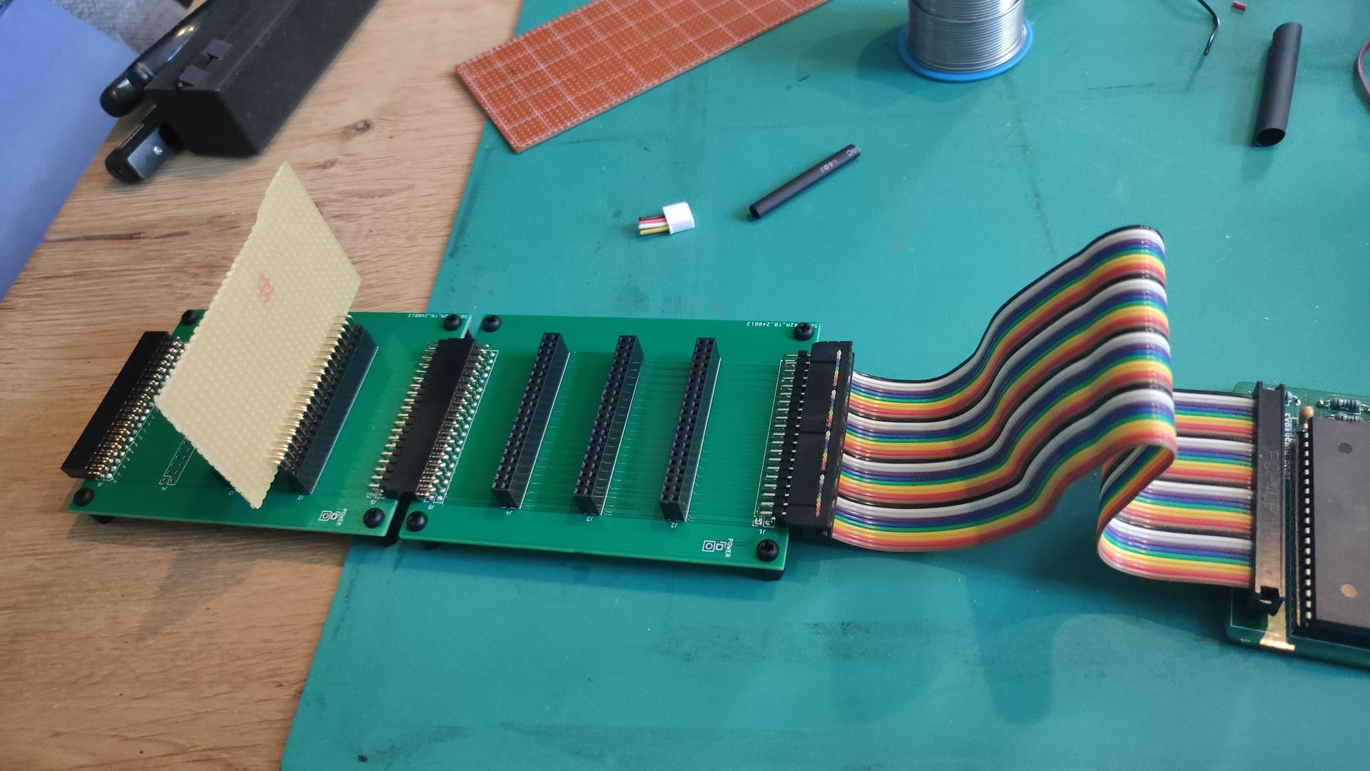
The backplane was designed to be chained together.
(Horizontal female – male connection)
The vertical cards I’ve planned to make are:
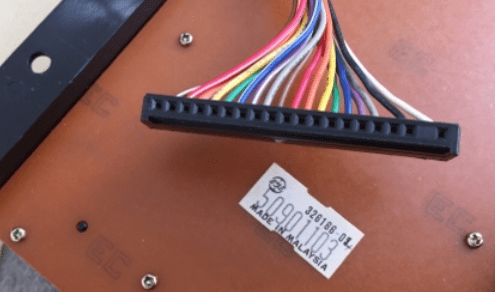
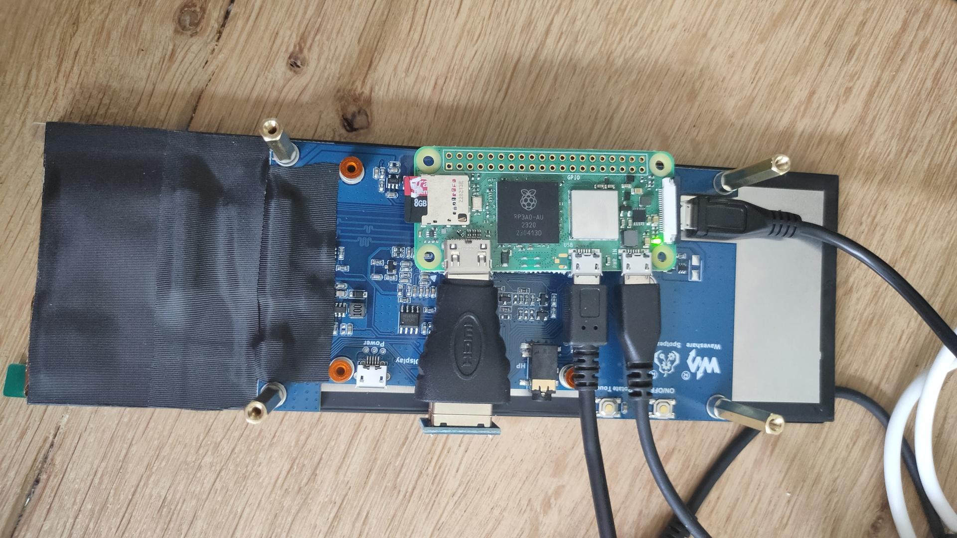
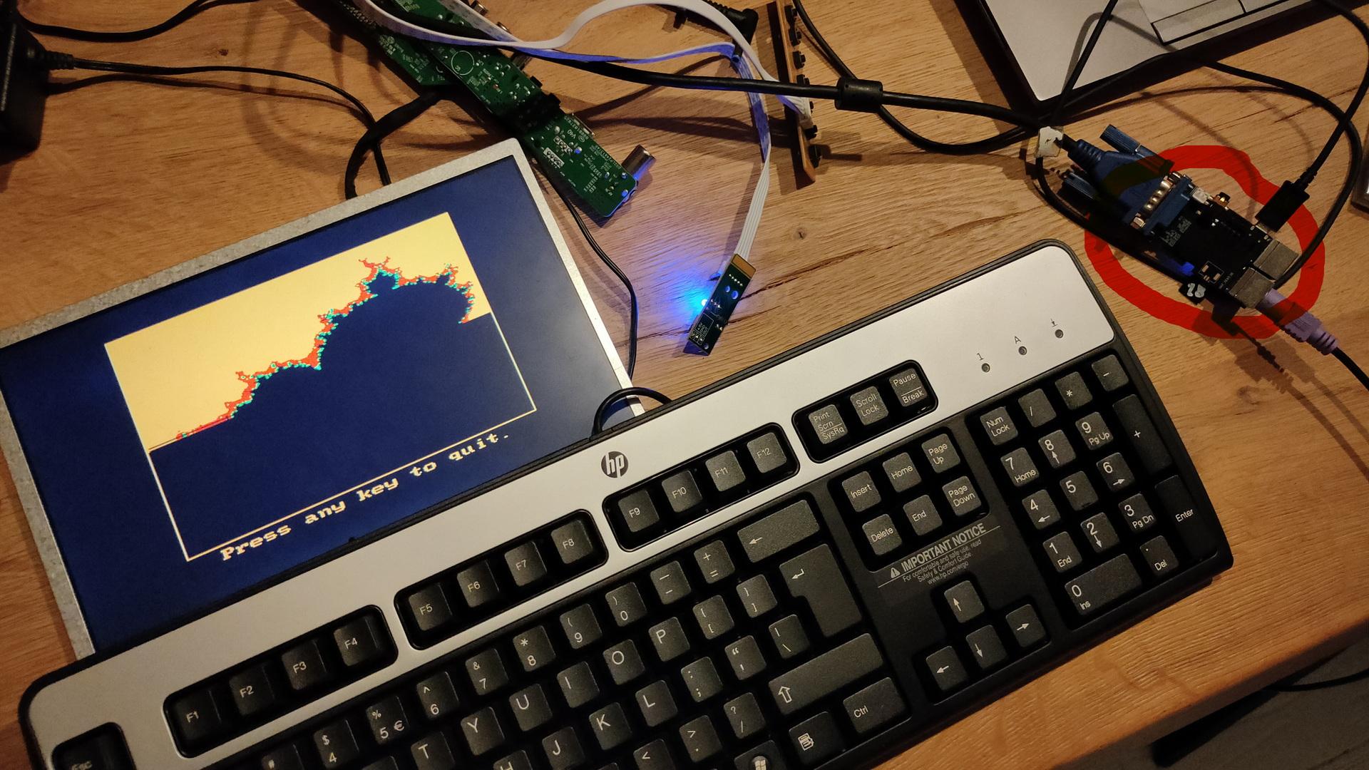
Testing the first keyboard. It is the 8085-SDK hex matrix keyboard.
It is running on a Raspberry Pi Zero 2, without X server.
So the images are displayed using the framebuffer.
Also the touch data is read using evdev and the raw devices.
Todo:
Bash test and configuring the OS for testing.
cat <<EOF >> /boot/config.txt
hdmi_group=2
hdmi_mode=87
hdmi_timings=400 0 100 10 140 1280 10 20 20 2 0 0 0 60 0 43000000 3
display_rotate=3
EOF

# Image testing
apt-get install fbi
sudo fbi -d /dev/fb0 -T 1 8085.png  -a --noverbose

apt-get install python3-evdev python3-uinput evtest
evtest
First simple python test
import select
from math import floor
import sys
slot = 0

keysname=[["F","E","D","C","vect-int","reset"],
          ["B","A","9","8","GO","Single-Step"],
          ["7","6","5","4","Exam-reg","Subst-mem"],
          ["3","2","1","0","Exec","Next"],
          ]
keysnames=[["F","E","D","C","vect-int","reset"],
          ["B","A","L","H","GO","Single-Step"],
          ["PCL","PCH","SPL","SPH","Exam-reg","Subst-mem"],
          ["3","2","1","0",".",","],
          ]

for path in evdev.list_devices():
    device = evdev.InputDevice(path)
    if evdev.ecodes.EV_ABS in device.capabilities():
        break
else:
    sys.stderr.write('Failed to find the touchscreen.\n')
    sys.exit(1)

while True:
    r, w, x = select.select([device.fd], [], [])

    id_ = -1
    x = y = 0

    for event in device.read():

        if event.code == event.value == 0:
           if id_ != -1:
                yy = floor(( x - 600 ) / 700)
                xx = floor(( y - 1377 ) / 226)
                if yy < 4 and yy >=0 and xx < 6 and xx >= 00:
                     if slot == 1:
                         print(keysnames[yy][xx])
                     else:
                         print(keysname[yy][xx])

        elif event.code == ABS_MT_TRACKING_ID:
            id_ = event.value
        elif event.code == ABS_MT_SLOT:
            slot = event.value
        elif event.code == ABS_MT_POSITION_X:
            x = event.value
        elif event.code == ABS_MT_POSITION_Y:
            y = event.value
I came up with a simple matrix calculation
Pressing the 4 corner keys gave me x and y.
I took averages for min and max reading.
I don’t need pixel-perfect reading, and I noticed values between 960 and 3080 vertically.
We want 960 – 3080 into 4 blocks, but the middle should start @ 960.
So 3080/3 = about 700
700 / 2 = 350
block 1 starts 350 sooner than 960 is ~ 600
Upper key y coords = 600-> + 700
Next is 1300 -> + 700
converting to whole numbers using floor gives me:
floor(( y – 600 ) / 700)
NOTE: My x and y are rotated
Example using coordinates
1600, 1600
floor(( 1600 – 600 ) / 700) = floor(1,4…) = 1st row
(from row 0,1,2,3)
I’ve been busy programming Python and NodeRed for a client.
But these are the things I’ve done in the last days.
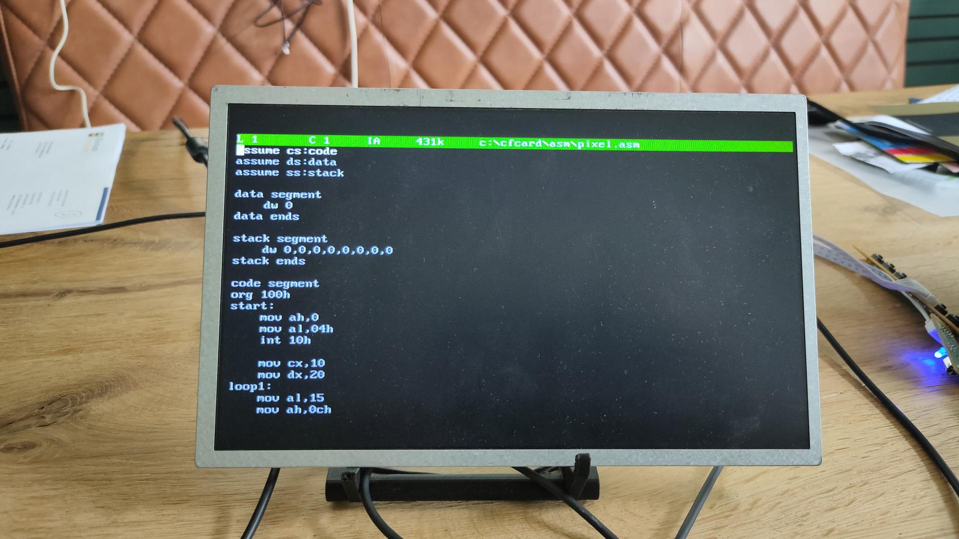
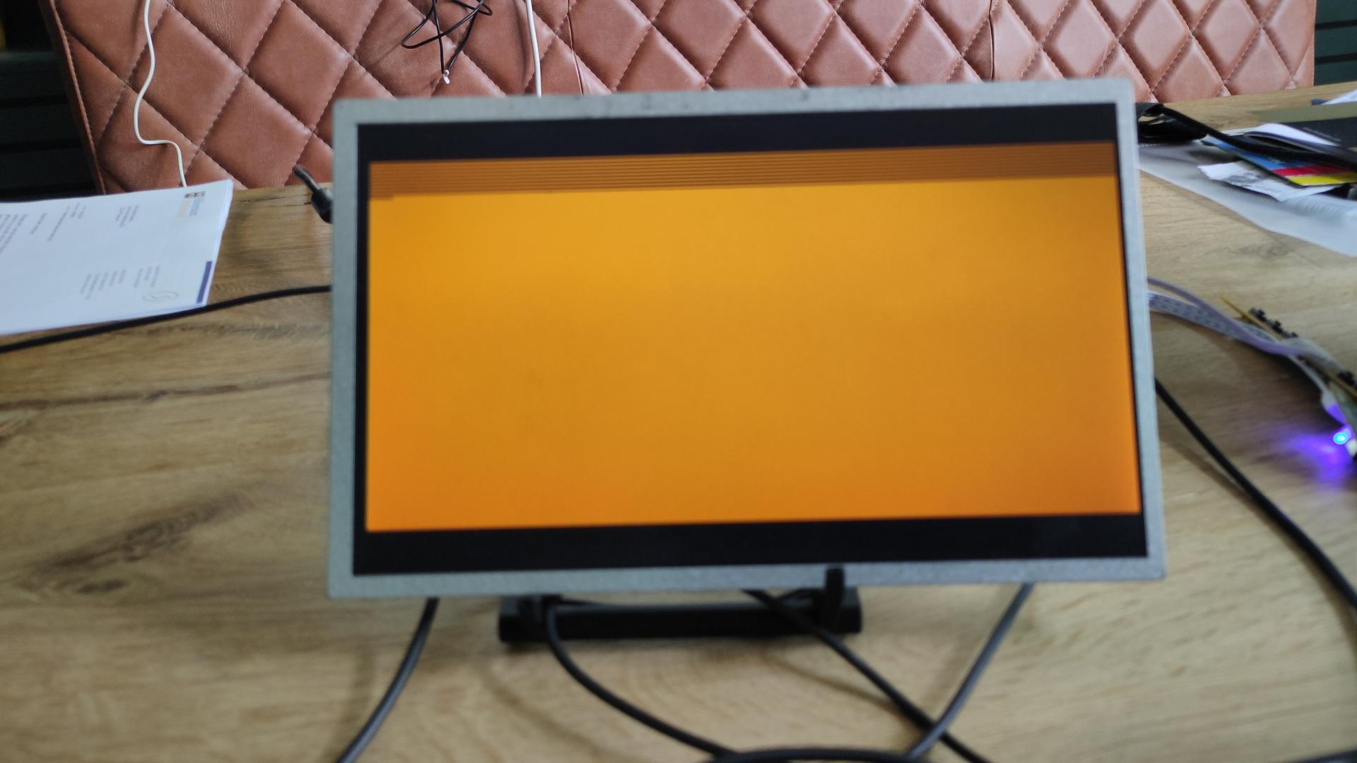
C64 Assembly:
Breaking borders, using sprites and multicolor font intro.

It does not look impressive, but I’ve learned a lot.
Found a new way (for me) to open borders and change border colours on predefined raster lines.
Sources will be posted.
KiCad tutorial, posted on YT also because I could not find many resources about the subject online. Maybe it’s helpful
Video editing using Kdenlive.
Edit: Even faster, use Netlabels, no need to join pins.
Press L (uppercase) select pin 1, name 1.
Press and hold insert until all pins named.
Copy paste socket 5 times and goto your PCB tab.
This movie is about creating a backplane for a 6502 SBC I’m building.
It is real-time and below 4 minutes.
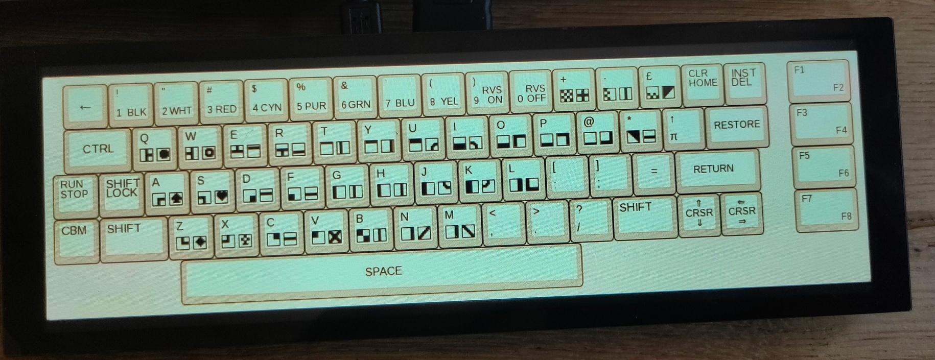
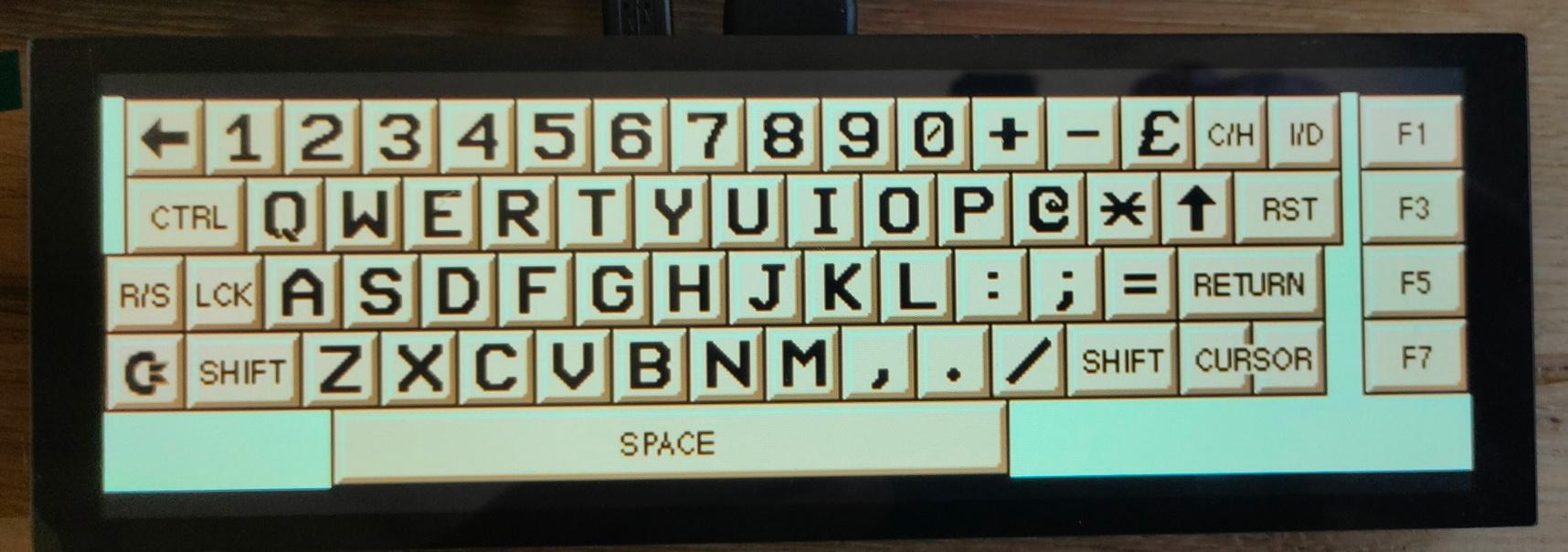
Multi Keyboard
My small multitouch screen came in.
This is for my previously mentioned multi-computer case.
It is going to show multiple keyboard layouts for different systems.
(See previous posts about this)
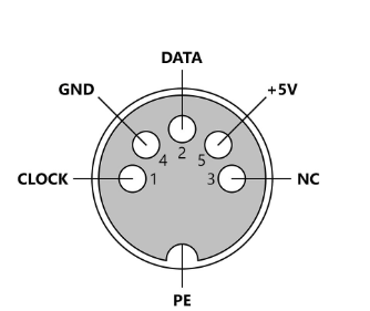
Waveshare display, Raspberry Zero as HID device, using USB and pin emulated keyboards. (c64 matrix, AT (DIN) keyboard, ps2 keyboard)
Some example screens
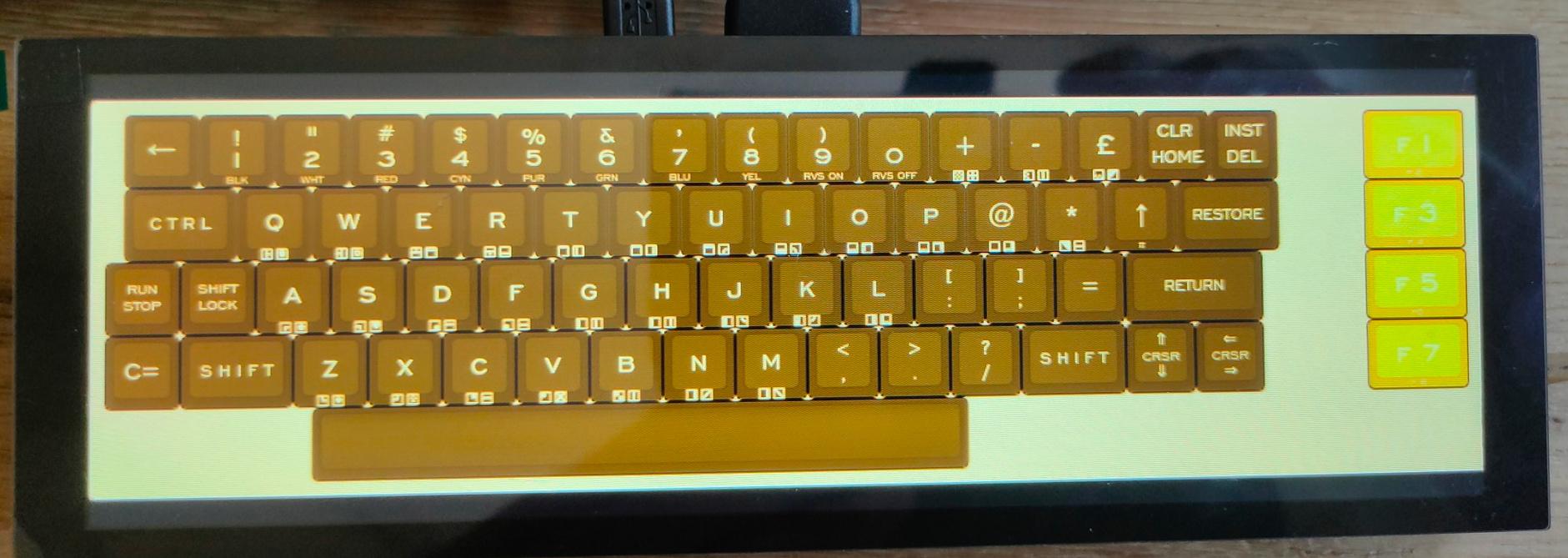
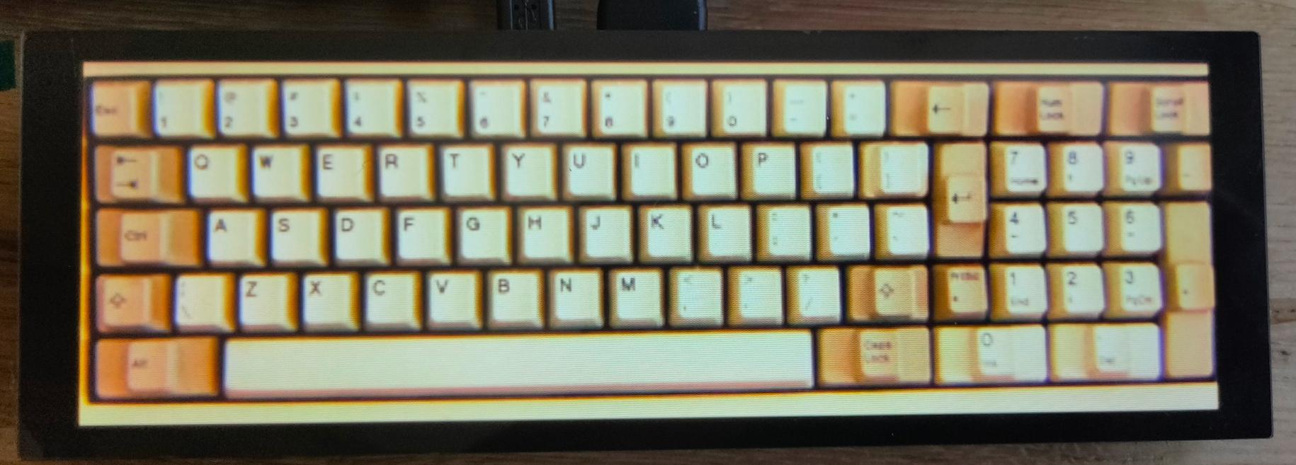
I’m also going to make a layout like the keyboards on my 8085

In the past I made a Etch a Sketch with my lasercutter.
Using two rotary encoders and the 64×64 matrix display I recently bought, I made a drawing thingy.
Like a Etch a Sketch.
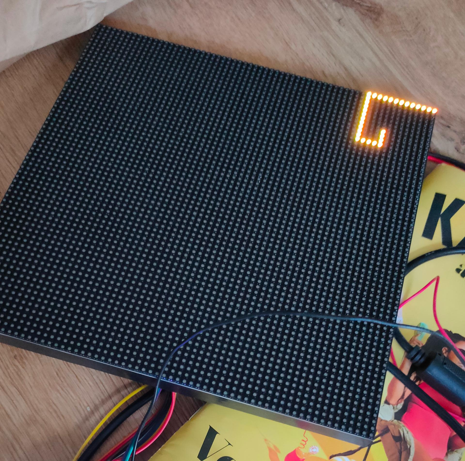
Some Circuit Python code.
Now I have to fix an out of memory issue using below.
And make a colour selection button??? 🙂
import time
import board
import displayio
import math
import vectorio
import rgbmatrix
import framebufferio
import array
import bitmaptools

import rotaryio
import board

encoder1 = rotaryio.IncrementalEncoder(board.GP27, board.GP26)
encoder2 = rotaryio.IncrementalEncoder(board.GP18, board.GP19)

last_position1 = 0
last_position2 = 0

# Release any existing displays
displayio.release_displays()

# --- Matrix Properties ---
DISPLAY_WIDTH = 64
DISPLAY_HEIGHT = 64

# --- Matrix setup ---
BIT_DEPTH = 2
matrix = rgbmatrix.RGBMatrix(
    width=64, bit_depth=2, height=64,
    rgb_pins=[board.GP0, board.GP1, board.GP2, board.GP3, board.GP4, board.GP5],
    addr_pins=[board.GP6, board.GP7, board.GP8, board.GP9, board.GP22],
    clock_pin=board.GP10, latch_pin=board.GP12, output_enable_pin=board.GP13)
colrs = 13
display = framebufferio.FramebufferDisplay(matrix, auto_refresh=True)
b1 = displayio.Bitmap(display.width, display.height, colrs )
palette = displayio.Palette(colrs )
palette[0] = 0x000000  # black
palette[1] = 0x964B00  # brown (light yellow)
palette[2] = 0x00FFFF  # cyan
palette[3] = 0x850101  # deep red
palette[4] = 0x7F00FF  # violet
palette[5] = 0xC46210  # orange
palette[6] = 0x3D9140  # Cobalt green
palette[7] = 0x004225  # british racing green
palette[8] = 0x8B008B  # dark magenta
palette[9] = 0x1F75FE  # crayola  blue
palette[10] =0x00308F  # air force blue US air force
palette[11] =0xBF00FF  # electric purple
palette[12] =0x08E8DE  # turquoise
g1 = displayio.Group(scale=1)
display.root_group = g1

bmp = displayio.Bitmap(64,64, 2)

tilegrid = displayio.TileGrid(bitmap=bmp, pixel_shader=palette)
g1.append(tilegrid)
display.auto_refresh = True

tilegrid = displayio.TileGrid(bitmap=bmp, pixel_shader=palette)
while True:
        position1 = encoder1.position
        if last_position1 is None or position1 != last_position1:

            if position1 > last_position1:
                position1 = position1 + 1
            if position1 < last_position1:
                position1 = position1 - 1
            if position1 < 0:
                position1 = 0
            last_position1 = position1
        position2 = encoder2.position
        if last_position2 is None or position2 != last_position2:
            if position2 > last_position2:
                position2 = position2 + 1
            if position2 > last_position2:
                position2 = position2 - 1
            if position2 < 0:
                position2 = 0
            last_position2 = position2

        bmp[position1,position2]=1
        tilegrid = displayio.TileGrid(bitmap=bmp, pixel_shader=palette)
        g1.append(tilegrid)
        display.auto_refresh = True
More info about this device
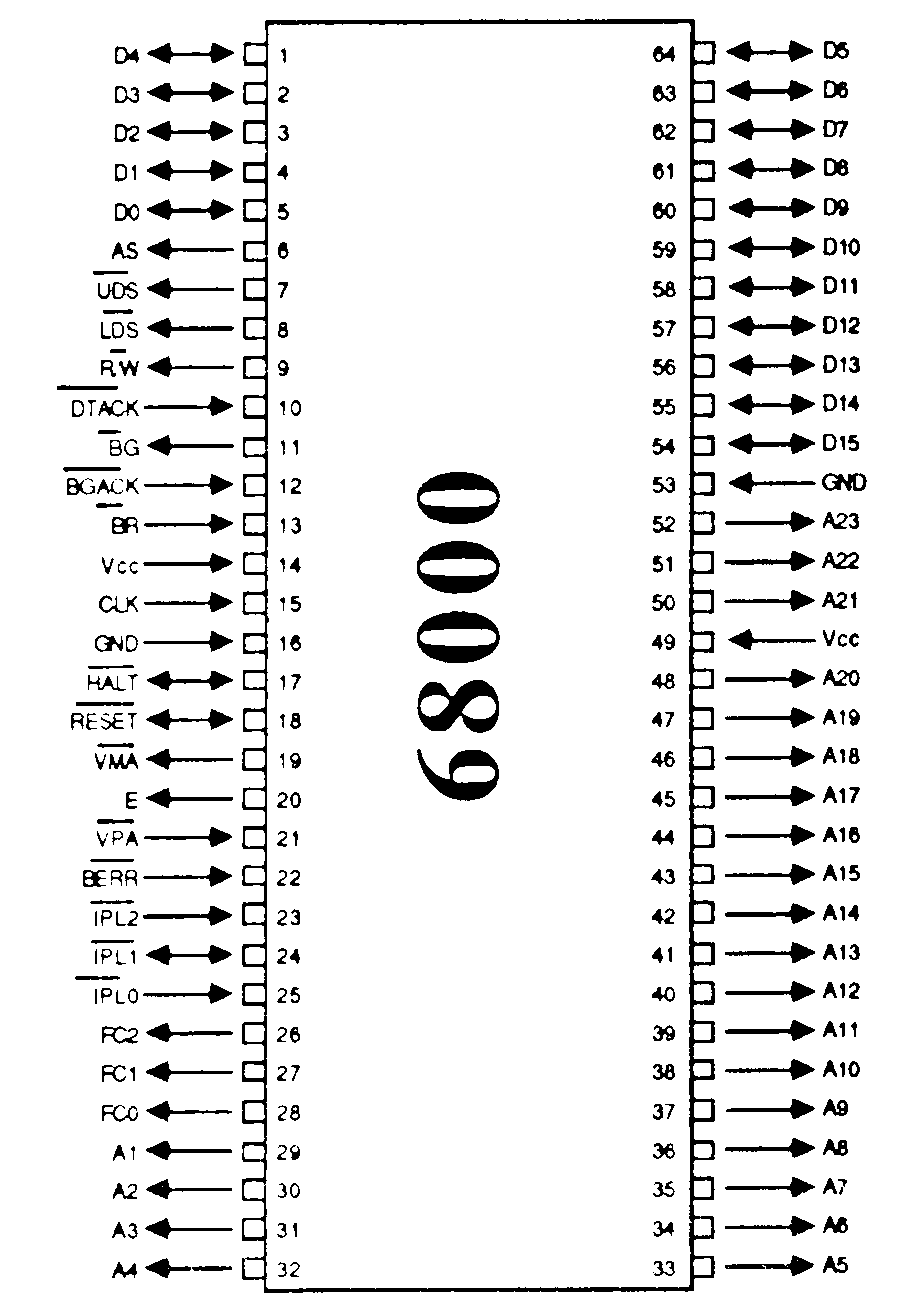
68000 Progress
My address decoder seems to work (using an ATF22v10C) See previous posts.
Also new Rom and Ram chips. These are 8 bits, but the 68000’s data bus we need two (Odd and Even Addresses)
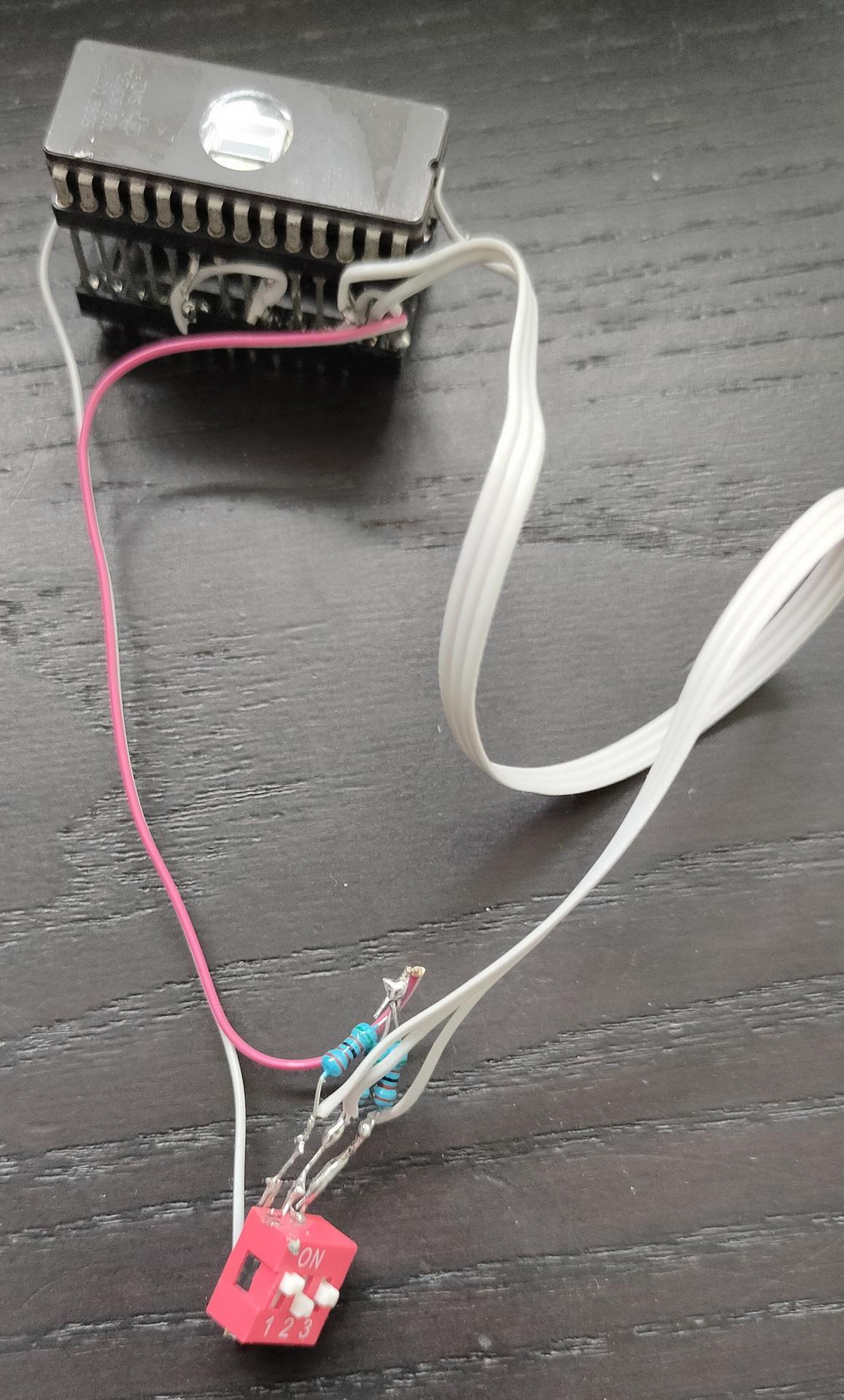
C64 Hacks
I made a proof of concept for a Rom switcher.
8 Different Roms can be selected using the dip switches.
(Dipswitches are being replaces bij something smarter in the future, like an Arduino Nano (like Adrian Black’s solution)
My other C64 stopped working, I need to make my PLA replacement.
https://www.henriaanstoot.nl/2024/05/27/notes-for-next-projects-i-made-using-our-short-holiday-in-madeira/
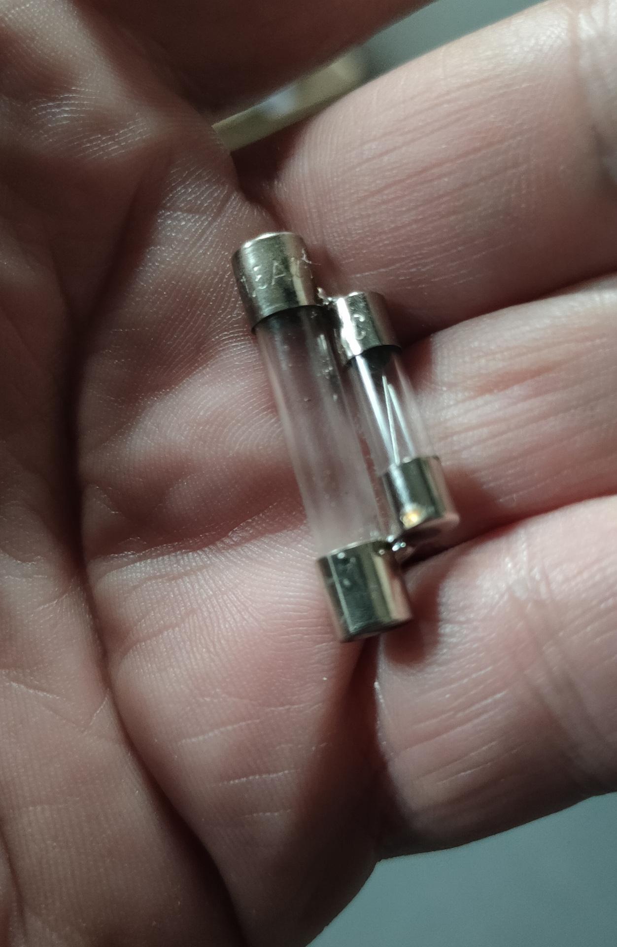
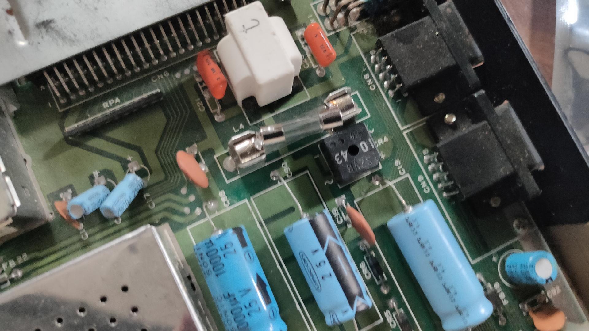
But beside the PLA not working, I noticed the glass fuse was blown.
I didn’t have a large fuse (32mm) but a small one.
(Fast 1.6A and 230V)
So some fancy soldering and fixed.
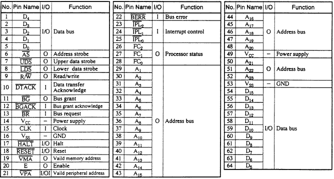
PROCESSOR FUNCTION CODES (FC0, FC1, FC2)
These function code outputs indicate the mode (user or supervisor) and the address space type currently being accessed.
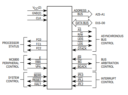
The following table shows the
meaning of these three bits.
FC2 FC1 FC0 Meaning
0 0 0 Not used
0 0 1 User data
0 1 0 User program
0 1 1 Not used
1 0 0 Not used
1 0 1 Supervisor data
1 1 0 Supervisor program
1 1 1 Interrupt Acknowledge
These outputs can therefore inform external circuitry what is happening
inside the 68000. They could, for example, be used to switch in differentbanks of memory.
Using a small 8266 with a display, I wanted to see if it’s useful to monitor this information.
So using a trick with the uln2804/uln2803 as level convertor (don’t connect the VCC, and the output will drop to a level that is around the 3.3v.
(I was out of bi-directional level convertors)
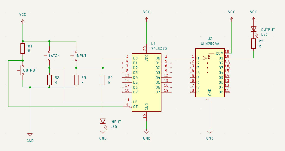
Latch demo
I’ve been using latches in the past, but I wanted to show how it works using a little demo setup.
Below movie is for the Bus Controller I posted recently.
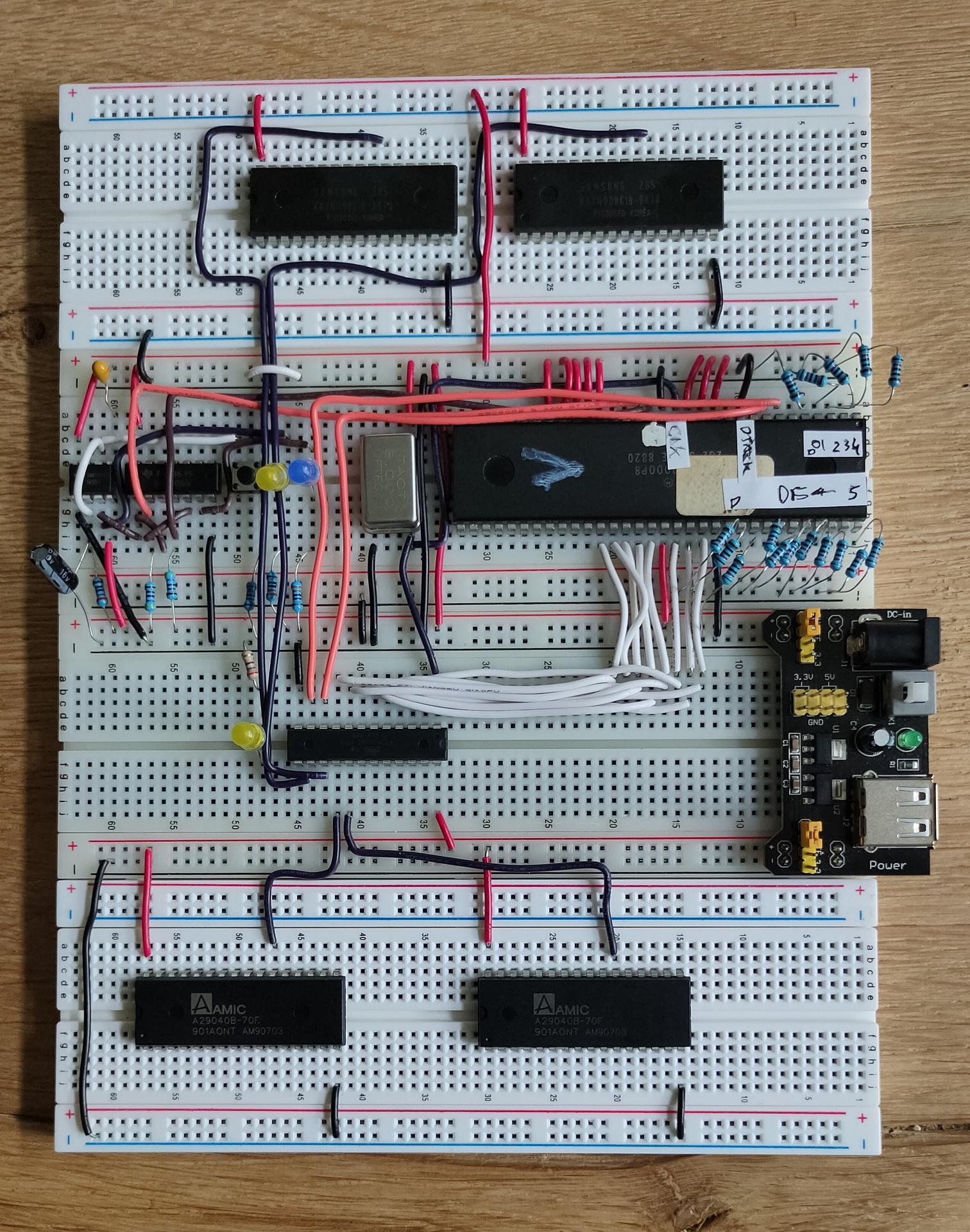
While busy fixing my business site, and working for a customer, I build a testing rig for the 68000.
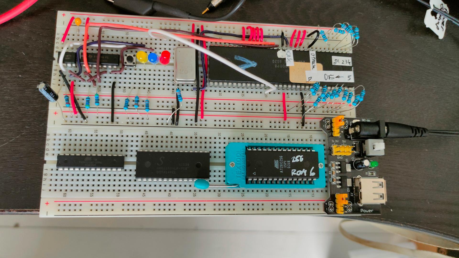
I first made a power-on reset schematic.
The timing is different from the 6502 power-on reset, and the 68k needs HALT and RESET being pulled low.
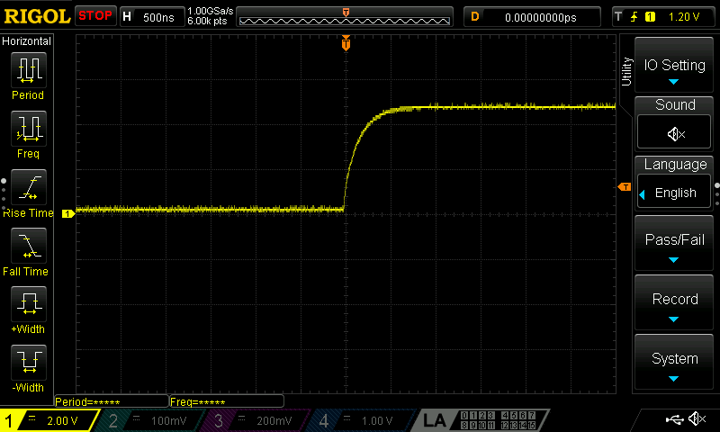
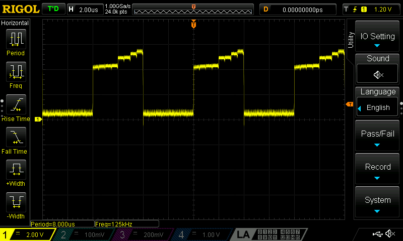
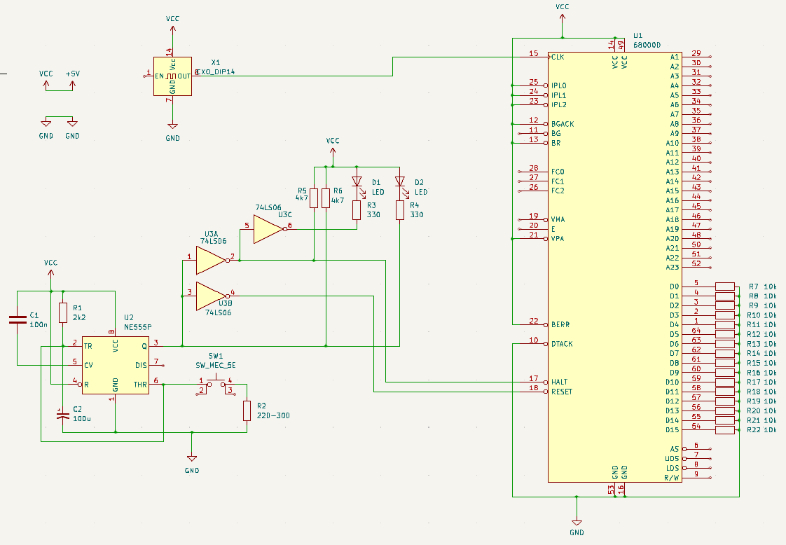
All Data lines are pulled low, emulating opcode 00 00
https://68k.hax.com/ORI%20to%20CCR
This will do nothing weird, and will increment the address and try to read the next opcode.
Resulting in an endless incrementing address bus, I’ve put a Led (Red)on Address A17.
Yellow is /RESET signal and Blue /HALT
For my 68000 POC I’ll need a way to test Address and Data buses. Something I also wanted for my 6502.
So I drew a schematic to make a generic bus manipulator.
(Address, Data and some control lines)
Devices I want to control:
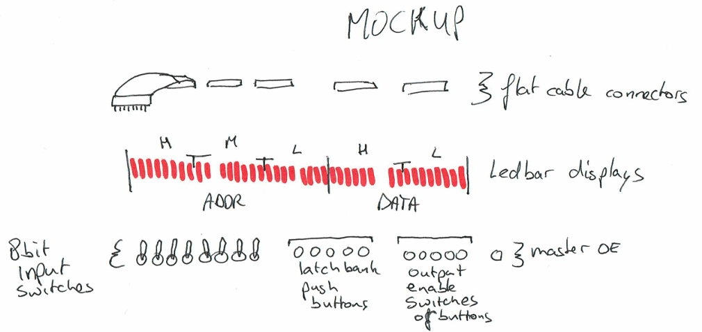
I will be using 8 input switches I can latch into 74HC373 chips.
(3x 8 bit for addresses, or 2x 8 bit and extra control lines + 2x 8 bit datalines)
Using ULN2804A or ULN2803A darlingtons I can use ledbars to display the bus data AND the latched data.
Using 5 pushbuttons I can choose which one (or multiple banks will be latched.
Other 5 buttons shall control the OUTPUT enable (OE), which also can be toggled using 1 master switch.
(Not yet in the schematic)
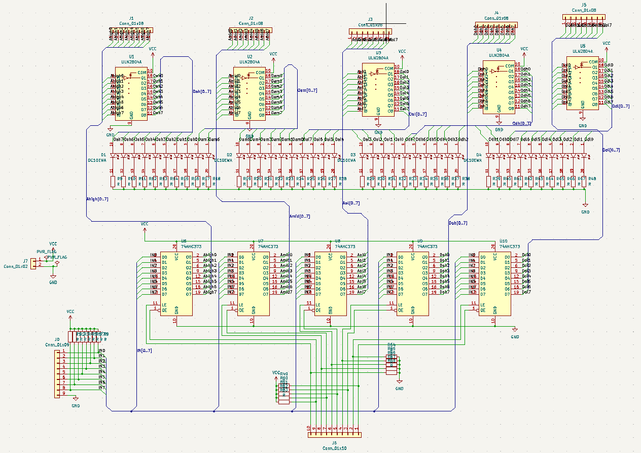
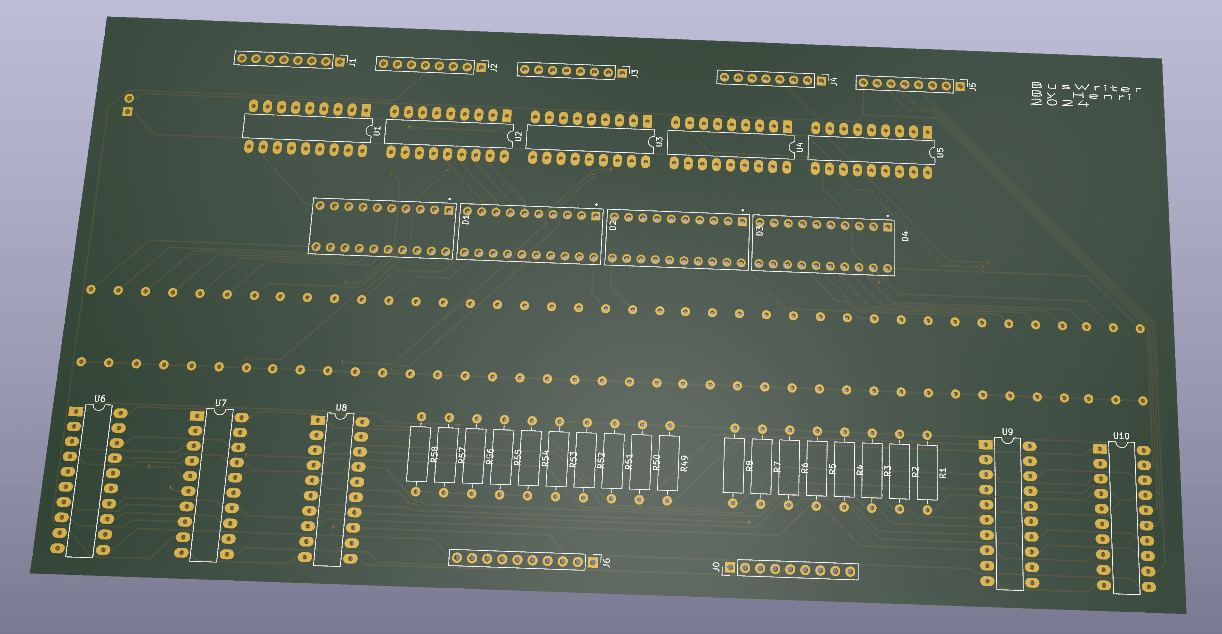
After testing, I will put the Kicad files online.