While working on a client project, I tested multiple displays.
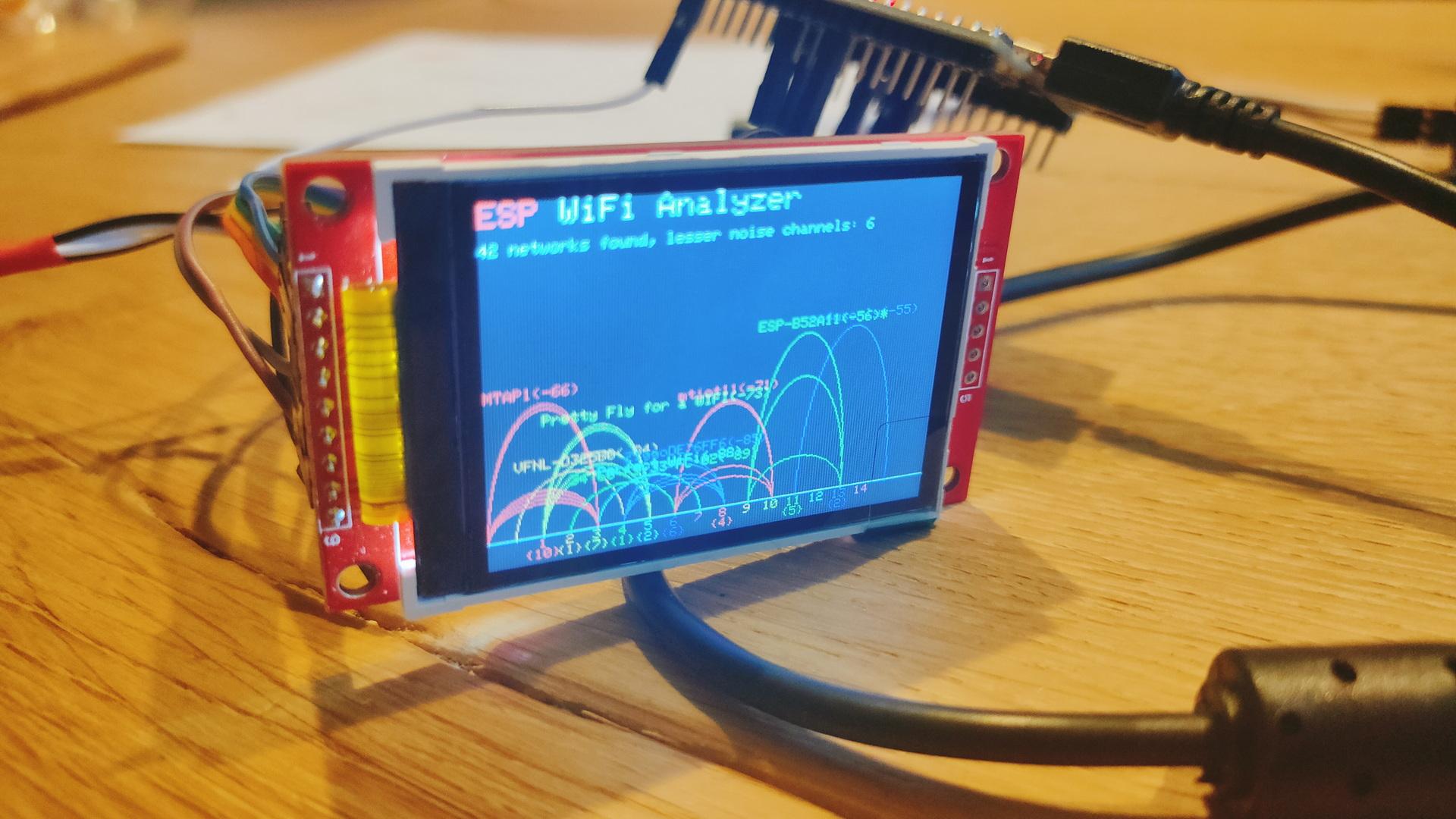
- ILI9341
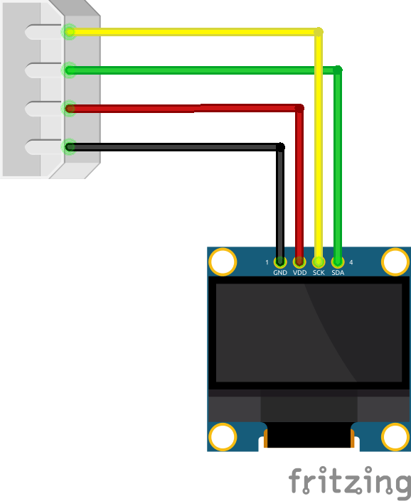
- 1.3inch SPI TFT LCD Display RGB (ST7789)
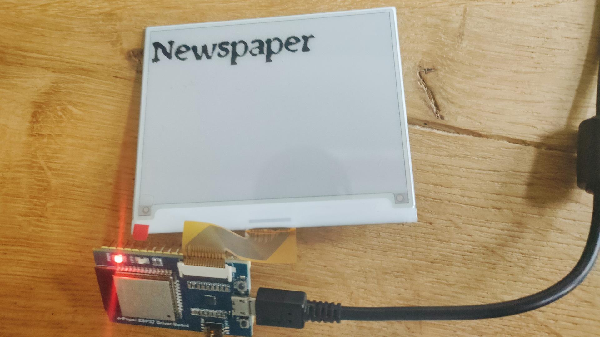
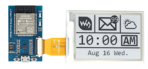
- Waveshare 4.2 Epaper with ESP32 Controller
I thought it was fun to connect the Epaper to ESPHome.
It was not without problems. For example, the ESPHome editor gave squiggly lines under type.
This has to be changed in the libraries.
(Already notified developers)
model: 4.20in-V2 does not work .. use model: 4.20in-v2
esphome:
  name: epaperqoute
  friendly_name: epaperqoute

esp32:
  board: esp32dev
  framework:
    type: arduino

# Enable logging
logger:

# Enable Home Assistant API
api:
  encryption:
    key: "tzRSzZky3Jk+hUYtiybzT90kxxxxxxxxxxxxxxxxxxxxx="

ota:
  - platform: esphome
    password: "4f127e114a7a44fxxxxxxxxxxxxxxxxxxxxx"

wifi:
  ssid: !secret wifi_ssid
  password: !secret wifi_password

  # Enable fallback hotspot (captive portal) in case wifi connection fails
  ap:
    ssid: "Epaperqoute Fallback Hotspot"
    password: "yLSoxxxxxxxxxx"

captive_portal:


external_components:
  - source: github://pr#6209
    components: [ waveshare_epaper ]

text_sensor:
  - platform: homeassistant
    entity_id: input_text.epaper_display_text
    id: epaper_display_text
    on_value:
      then:
        - component.update: epaperdisplay

spi:
  clk_pin: GPIO13
  mosi_pin: GPIO14

# Upload own ttf to a directory in esphome/fonts using file editor in Home Assistant
font:
  - file: "fonts/newspaper.ttf"
    id: tahoma
    size: 64

http_request:
  verify_ssl: false

# image test
online_image:
  - url: "https://www.henriaanstoot.nl/epapertest.png"
    id: example_image
    format: PNG

#it.image(0, 0, id(example_image));

display:
  - platform: waveshare_epaper
    id: epaperdisplay
    cs_pin: GPIO15
    dc_pin: GPIO27
    busy_pin: GPIO25
    reset_pin: GPIO26
    model: 4.20in-v2
    reset_duration: 200ms
    update_interval: never
    lambda: |
           it.printf(0, 0, id(tahoma), "%s", id(epaper_display_text).state.c_str());