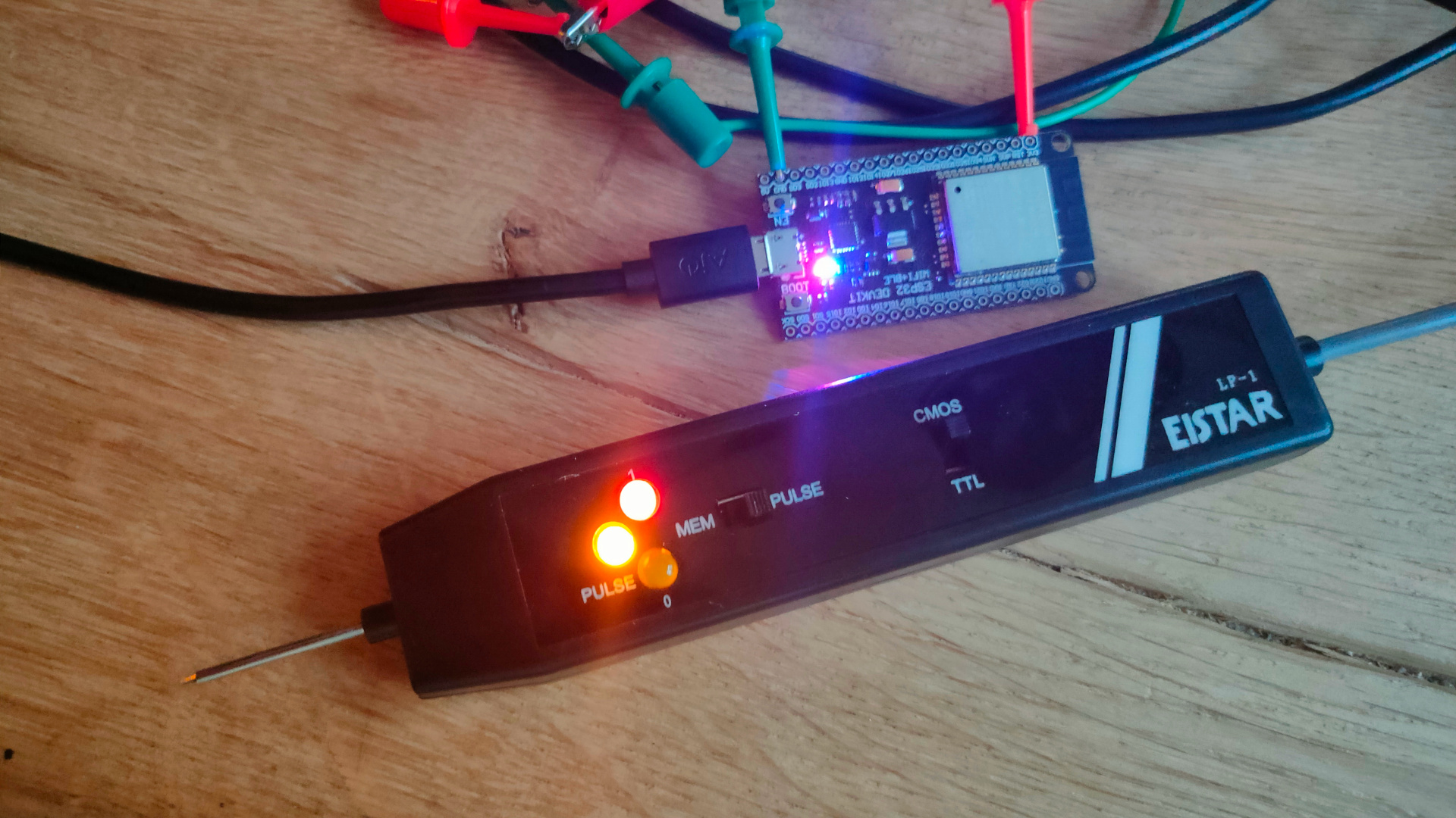
Today I got the EIStar LP-1. Its just a cheap easy probe, but does the job. My version is only TTL and this one is TTL/CMOS (cmos is better when measuring arduino’s outputs) TTL – Logic 1 = 4.75 -> 5V CMOS – Logic 1 = more around the 3.3/3.7V
Only thing my version has which i’m missing is a pulse detector. One millisecond puls gets clocked into a latch and keeps a led on.
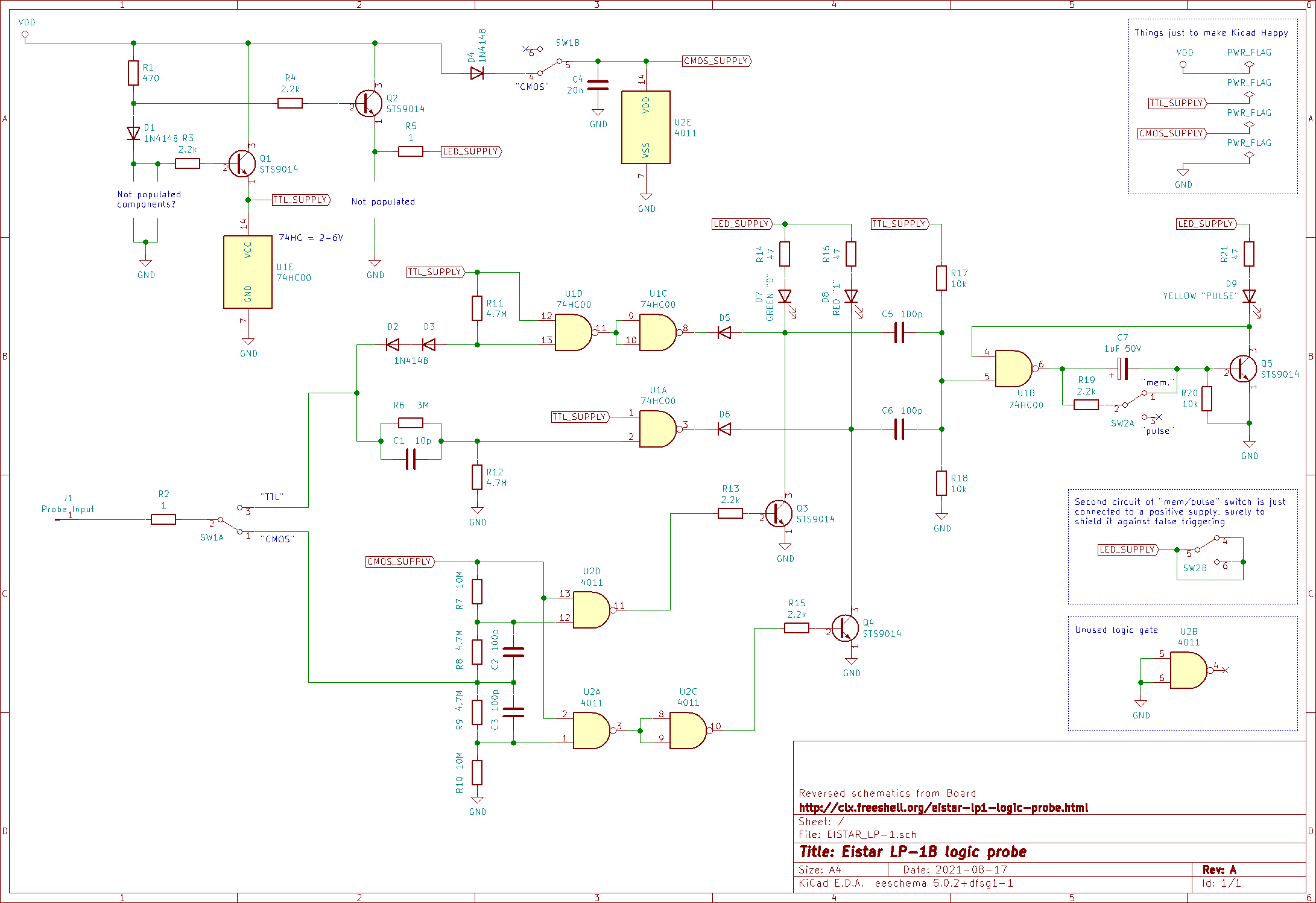
Schematic I found (some similarities can be seen with my version)
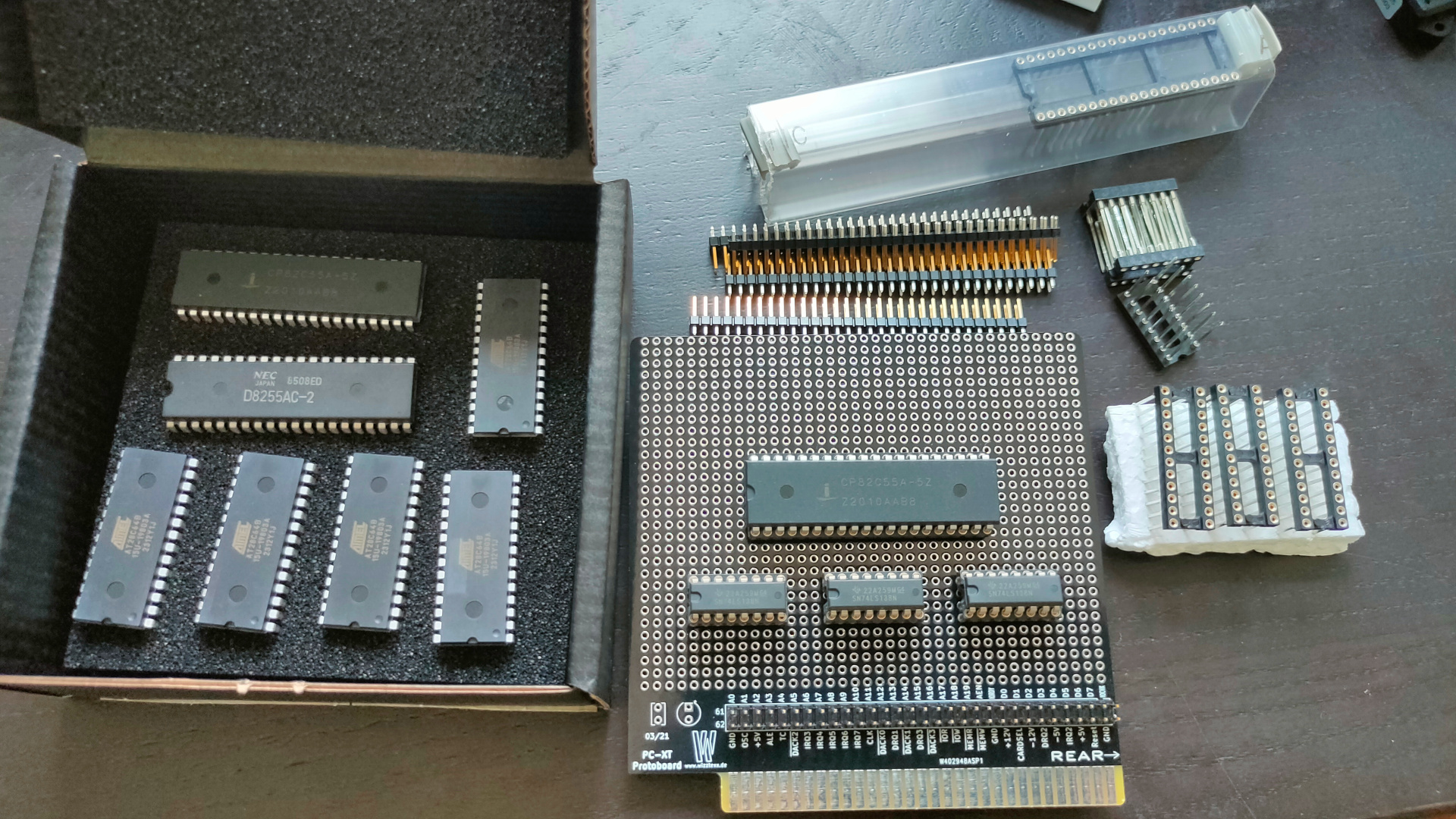
While working on a Lidar project, my mouser components came in.
Now I have to find a IO address decoder schematic I made a while ago.
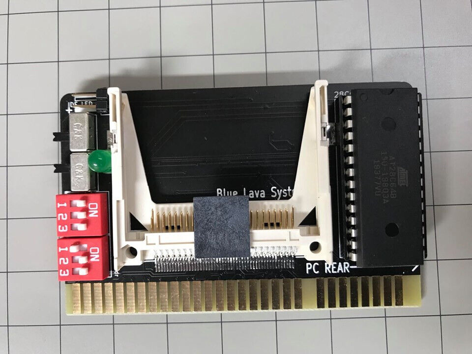
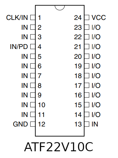
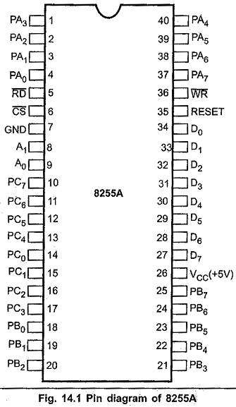
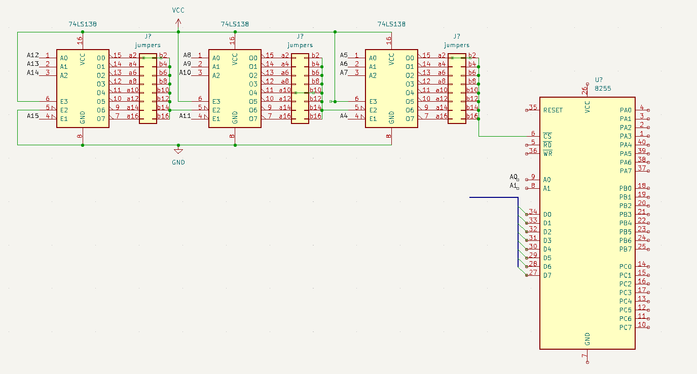
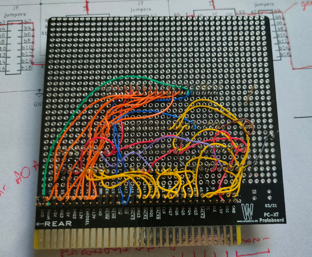
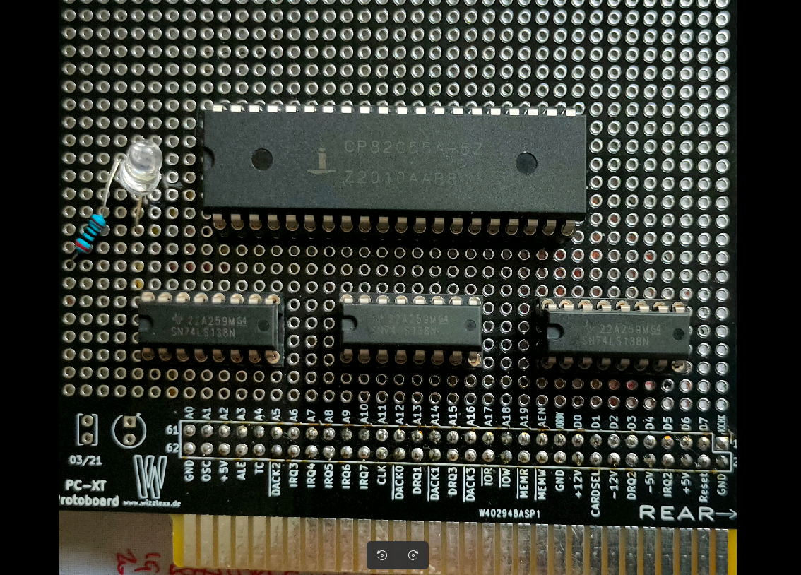
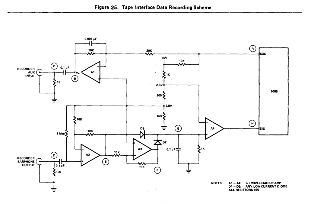
This ISA board is going to have a Wirewrapped setup. There is a 8255 IO chip, and uses 3x 74138 for IO address decoding, OR i will use a setup i’ve made for my 6502 using an atf22v10.
What to controll using this 8255? First some Leds, later a LCD display.
Below the 3 mentioned IC’s
The 8255 is a chip like the 6522 used in my DIY 6502 elsewhere on my site.
Overview of comparable IO chips. ( Not interchangeable due to bus timing!) Most of them have 8 data lines and 2x 8 IO bi-directional lines.
CHIP
NOTES
6522
6502 based machines
8255
8088/8068 based machines
Z84C2008
Z80 (called PIO)
8155
8085 / 8088
8520
68000 amiga
6821
6800
6821 example
UPDATE 20230702
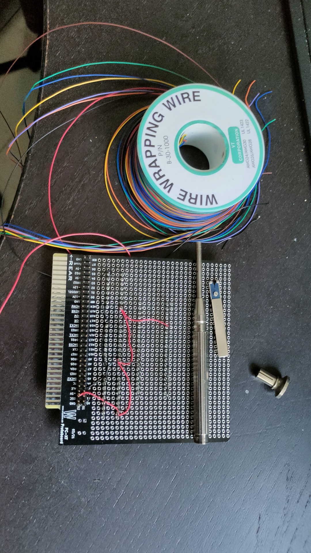
Started wirewrapping, luckily i’ve got a big choice of colors. That makes finding the right signals a breeze.
UPDATE 20230703
Found my schematic
Above uses 3 74138 decoders, address can be “programmed” using jumpers (not used on my prototype board) . Address 0400h in above example.
A15 – 0 A14,13,12 – decodes to OUT-0 A11 – 0 A10,9,8 – decodes to OUT-4 A7 – 0 A6,5,4 – decodes to OUT-0 A3 and A2 are not used (see note) A1 and A0 are register select on the 8255
Address 0000,0100,0000,xxrr xx can be a 0 or 1 the 8255 can be controlled using 0400h 0401h 0402h but also 0404h 0405h 0406h 0408h 0409h …. 040Ch ……
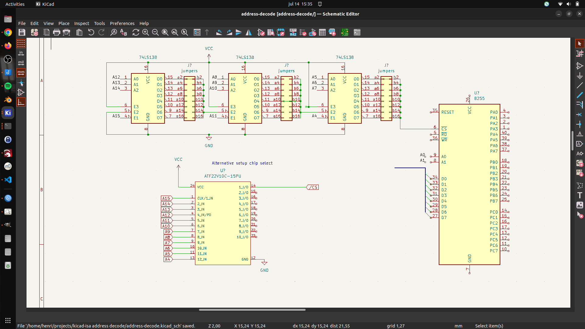
UPDATE 20230714 – Alternative address decode test with ATF22V10
UPDATE 20230803
UPDATE
Miswired second 74138. Tested with below code
mov dx,503h # control register
mov al,80h # output port a,b,c as standard IO/output
out dx,al # 16 bit IO mapped IO out
mov dx,500h # data register
mov al,0  # 0/ff all on/all off
out dx,al
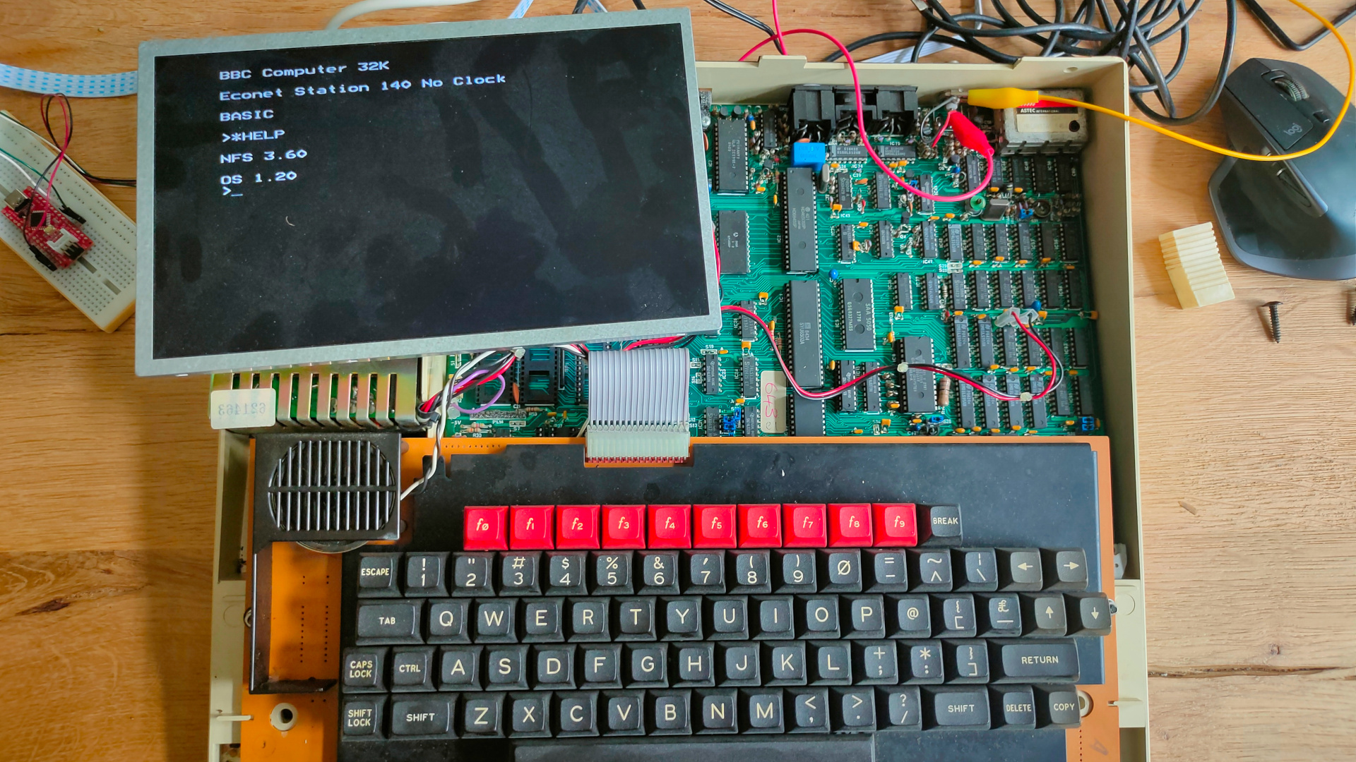
My BBC Acorn model B is working again. The original monitor is still dead.
Time to play with some machine code and ROMs.
My machine has a NFS rom installed. (NetFS)
Econet was Acorn Computers’s low-cost local area network system, intended for use by schools and small businesses. It was widely used in those areas, and was supported by a large number of different computer and server systems produced both by Acorn and by other companies.
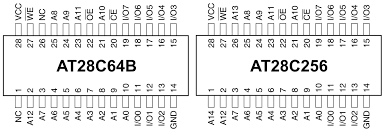
I found a ROM online called Gremlin. It is a 16K rom file. But at the moment I only got some 28C64 (8k) or 28C256 (32k) eeproms.
32k it is. But de beeb having address line A14 floating high, I need to flash the upper 16k of the 32k ROM.
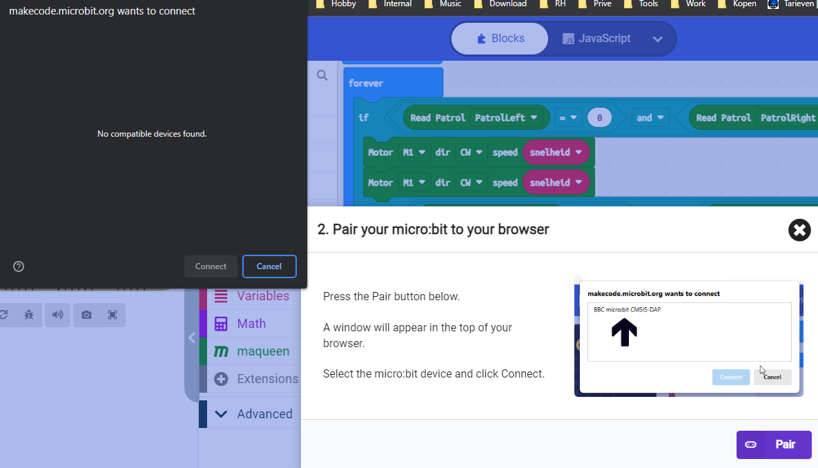
Uploading didn’t work Solution: Using chrome it had access to the usb port to upload, firefox didn’t work
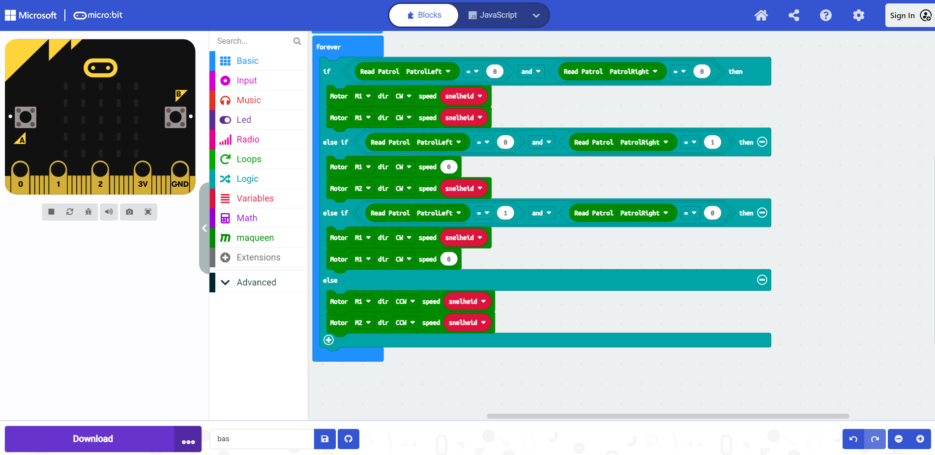
The program didn’t compile, faulty or zero size hex file. Solution: Wrong Maqueen library was in the examples (After changing, needed version update also, see below)
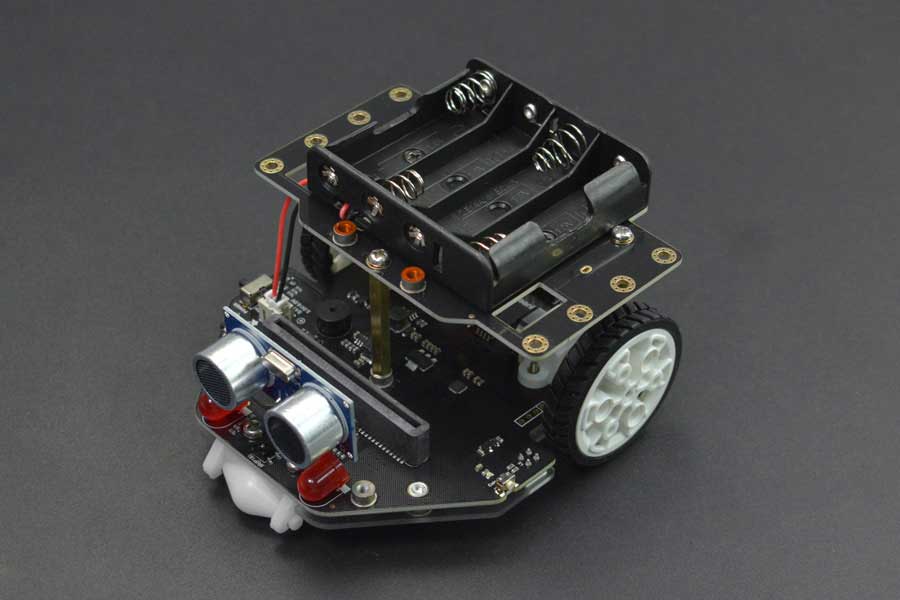
Not everything is in Dutch (I like English, but this is for the boy), maqueen V2 needed a lot of translation. (So we joined https://crowdin.com/project/makecode/nl to help translating the libraries)
Apparently my AI camera can be connected to this robot!
The board seems to be a X Golden Board, except for the missing logo on the motherboard.
Downloaded pcxtbios and compiled the eproms native in linux. So i don´t have to use dosbox any more. https://github.com/virtualxt/pcxtbios
cd pcxtbios
edit make_linux.sh if needed
./make_linux.sh

and you should end up with
eproms/27512/basicfc.rom
eproms/27512/basicf8.rom
eproms/27512/basicf6.rom
eproms/27512/pcxtbios.rom
eproms/27512/basicfa.rom
eproms/27128/basicfc.rom
eproms/27128/basicf8.rom
eproms/27128/basicf6.rom
eproms/27128/pcxtbios.rom
eproms/27128/basicfa.rom
eproms/27256/basicfc.rom
eproms/27256/basicf8.rom
eproms/27256/basicf6.rom
eproms/27256/pcxtbios.rom
eproms/27256/basicfa.rom
eproms/ibmxt/u18.rom
eproms/ibmxt/u19.rom
eproms/2764/basicfc.rom
eproms/2764/basicf8.rom
eproms/2764/basicf6.rom
eproms/2764/pcxtbios.rom
eproms/2764/basicfa.rom
I didn’t have enough 28C64, but the 28C256 has the same pinout. It just lacks A14 and A13
So I flashed the compiled ROMs for basic to different Eeproms
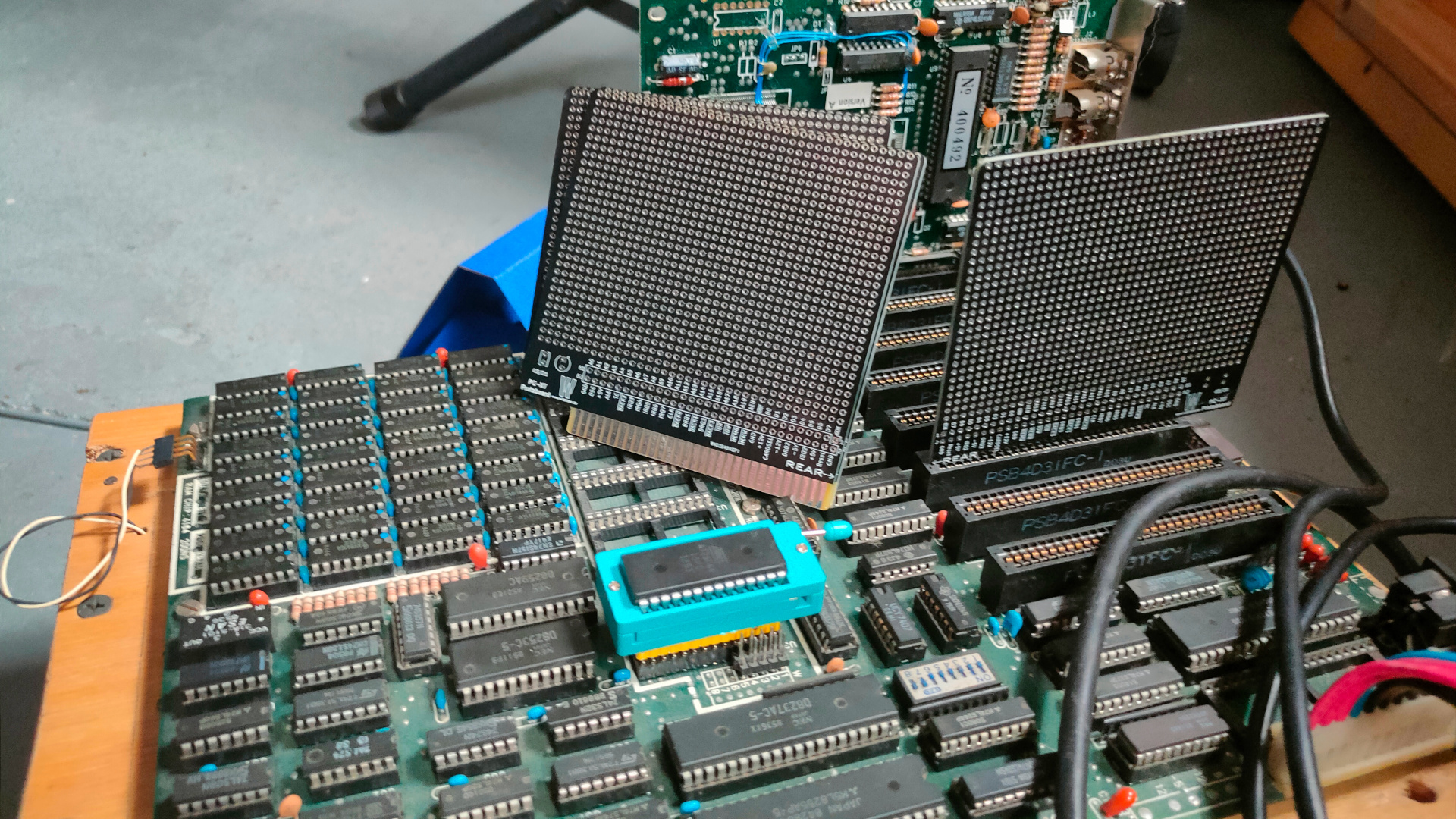
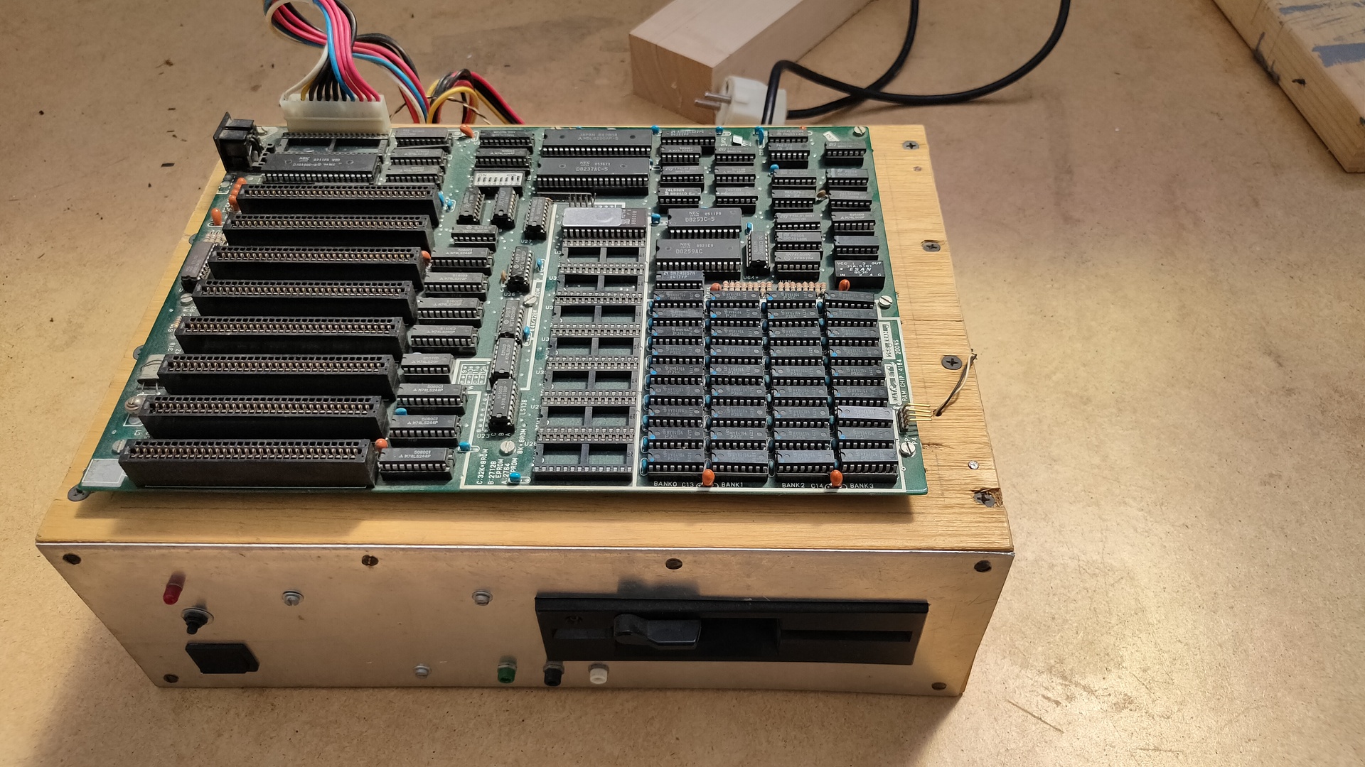
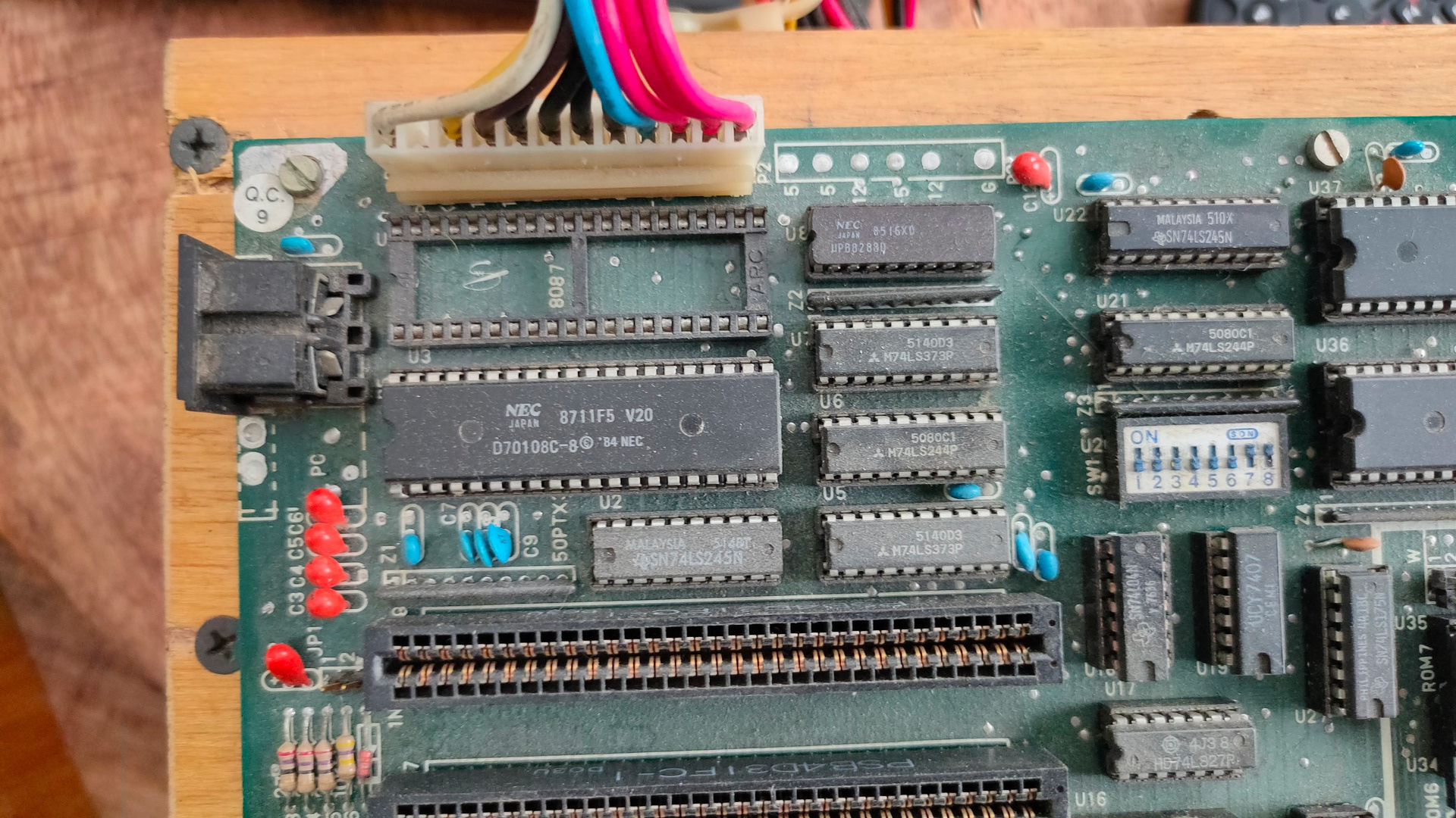
When selling a large part of my computer collection I kept a few odd pieces.
Amongst those was a 8088 DIY machine.
It is a 50PTX3 motherboard with a 8088 compatible CPU
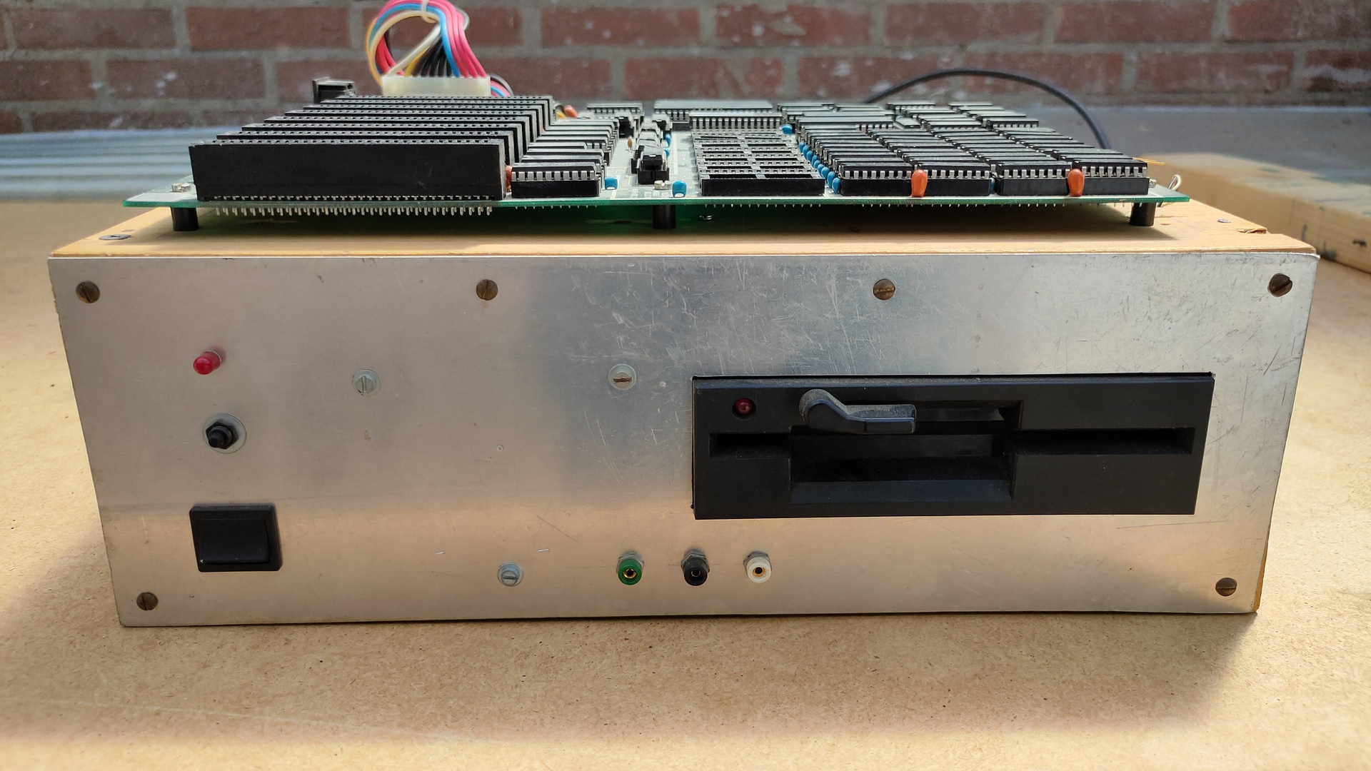
Power light (Not LED) and connected to power adaptor, not motherboard
Reset button??? not connected
Power switch
Mid center, 5v gnd and 12v
5.25″ drive not connected
Bottom
Tested the power adapter first, a nice 5V and 12V. Then I plugged the power in the Motherboard add plugged a test ISA card in the slot. After turning the machine on I saw the Address leds flashing
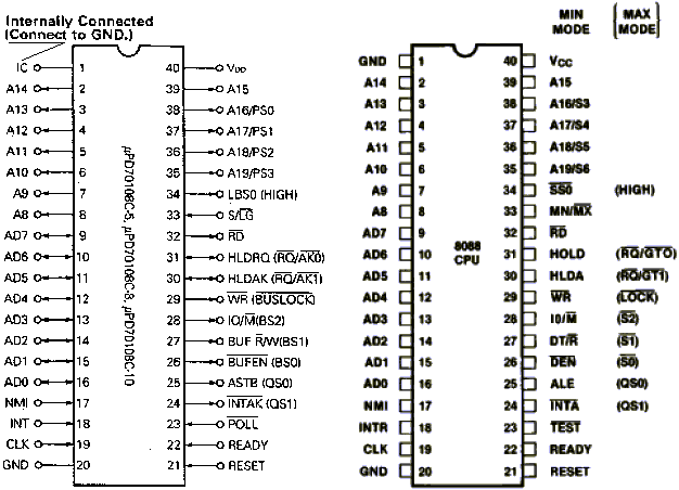
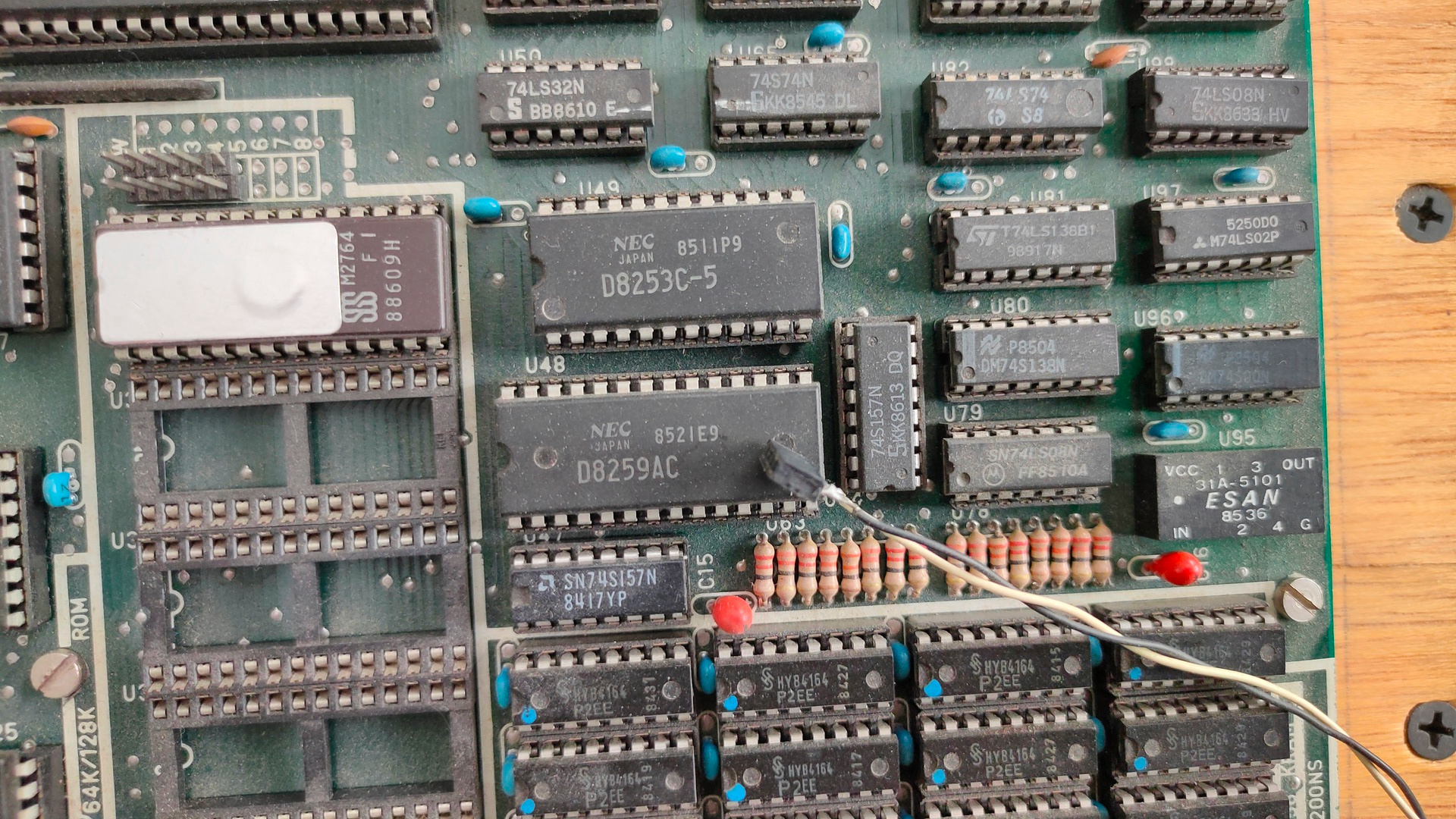
A NEC D70108C from 1984, which is 8088 pin compatible with Intel 8088 but faster, and has some extra functionality. The empty socket is for the 8087 Co-processor.
Nec V20 versus 8088
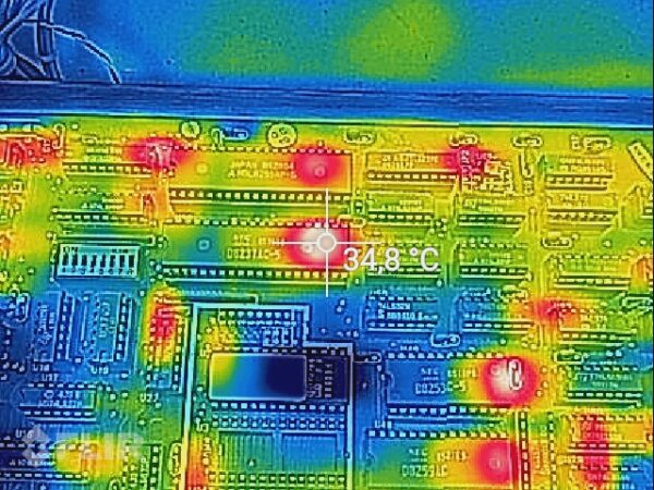
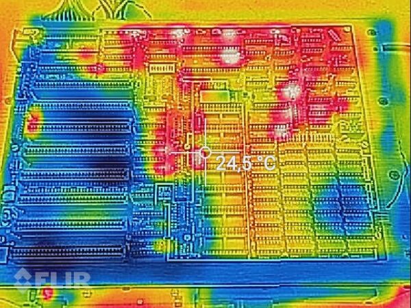
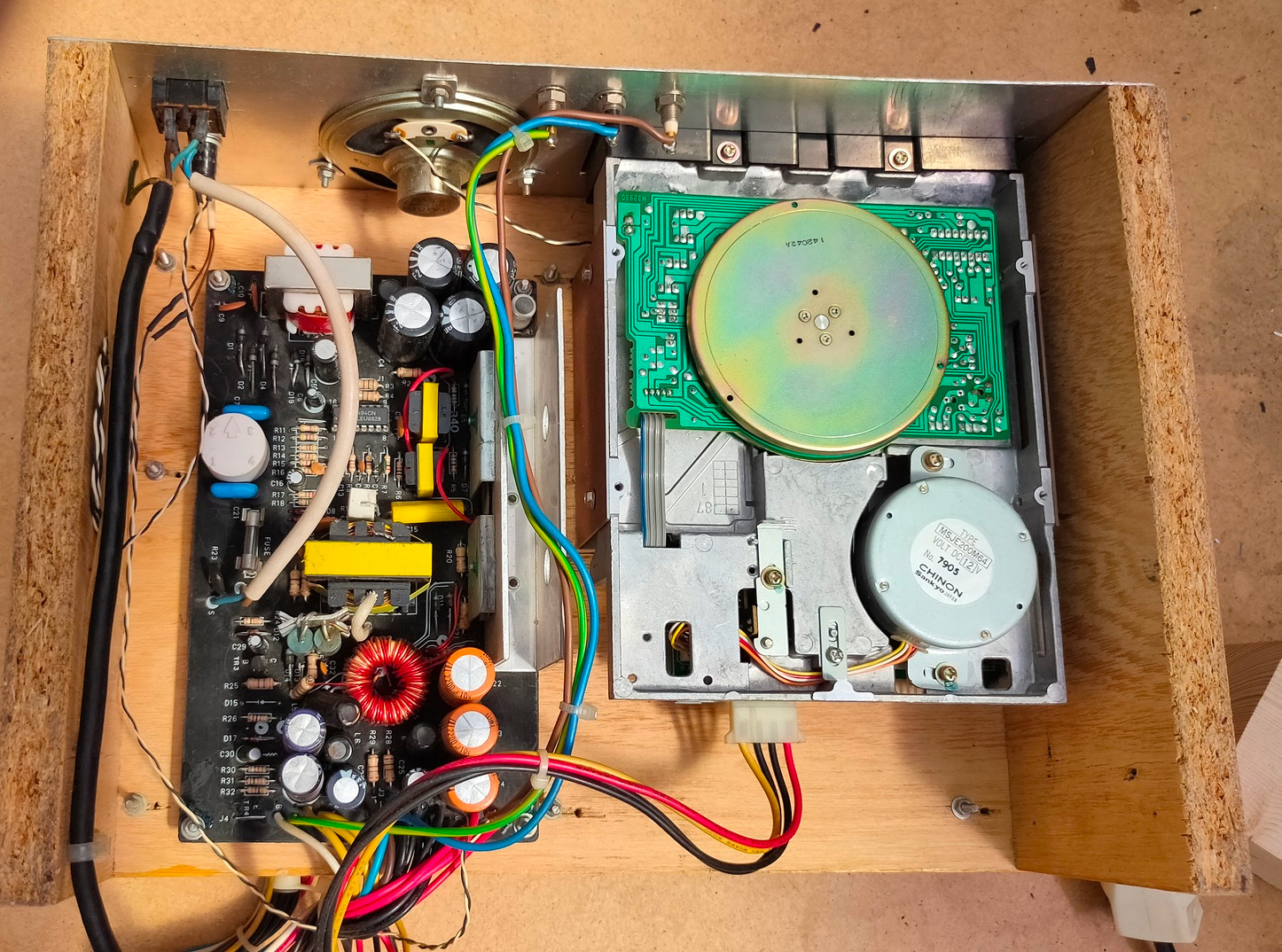
Everything pretty dirty
Rom 2764 (8Kb) and a disconnected speaker wire.
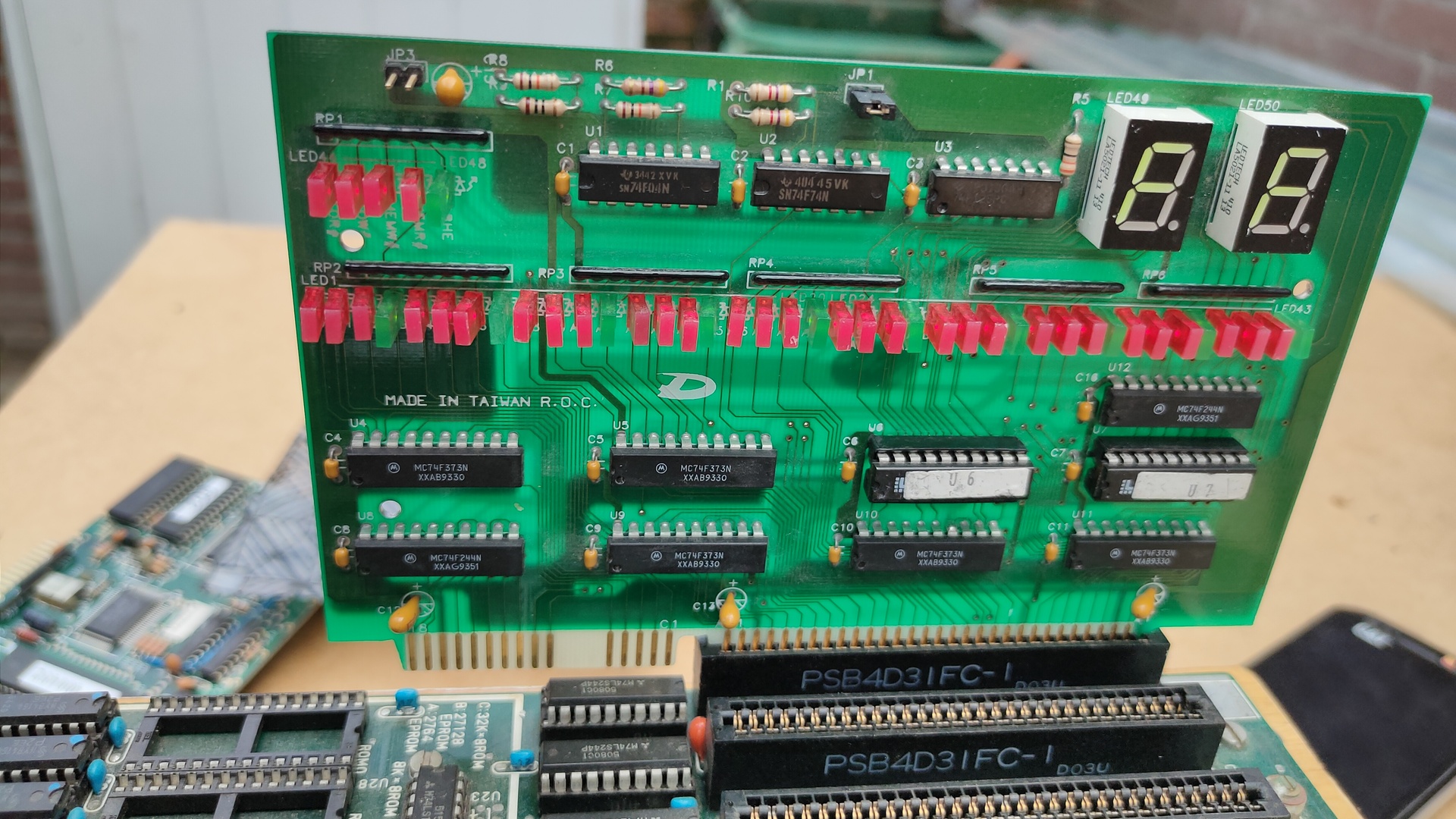
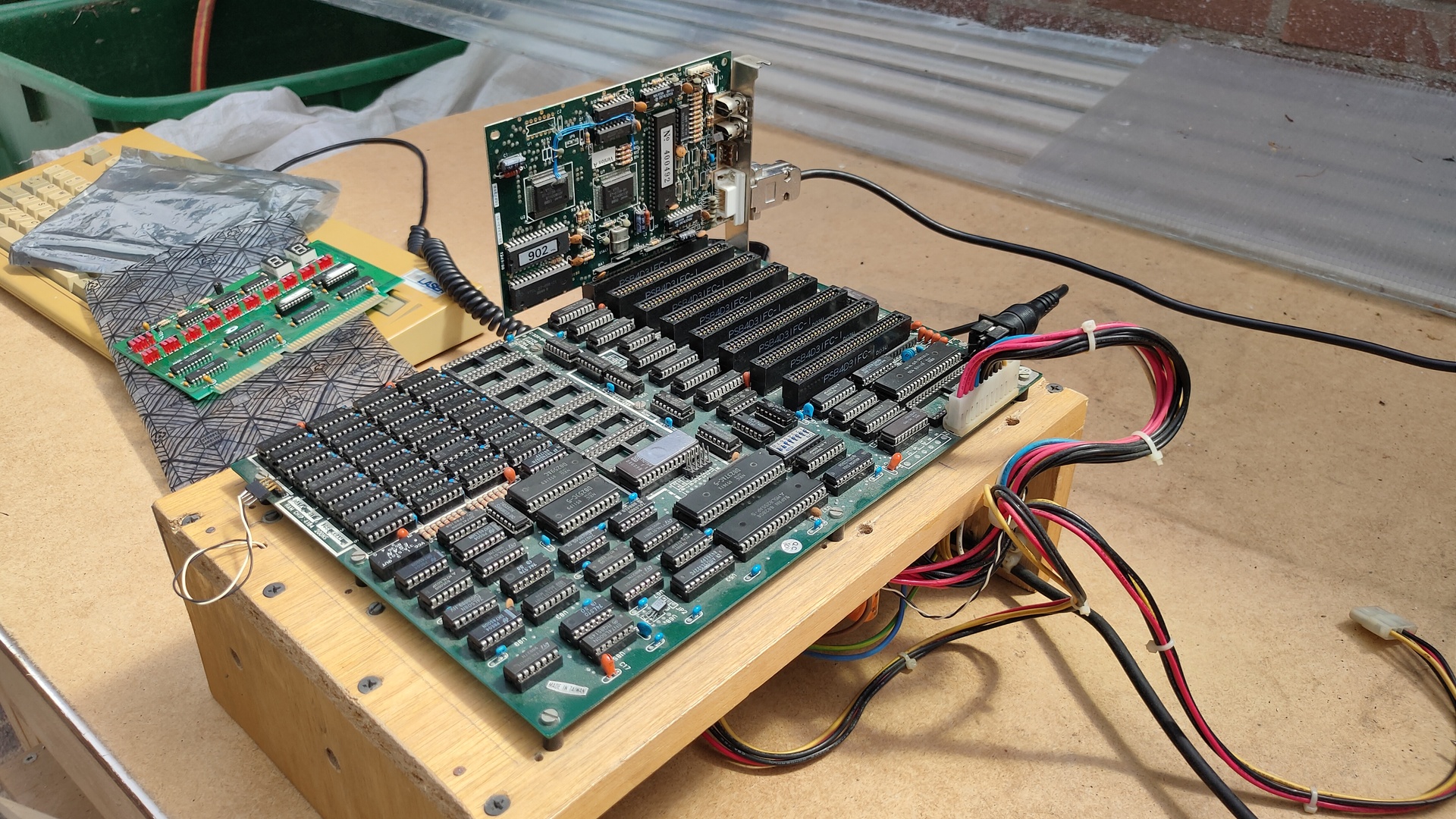
Adding an 8bit Isa hercules/CGA card.
It starts! .. But there is no Floppy controller (yet)
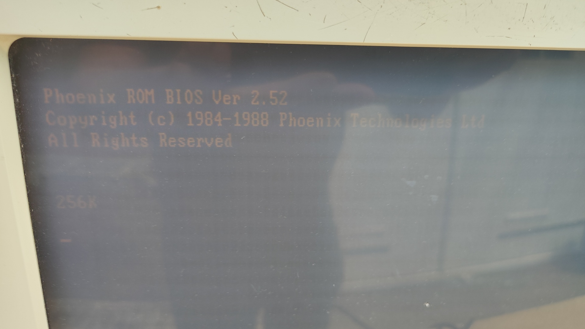
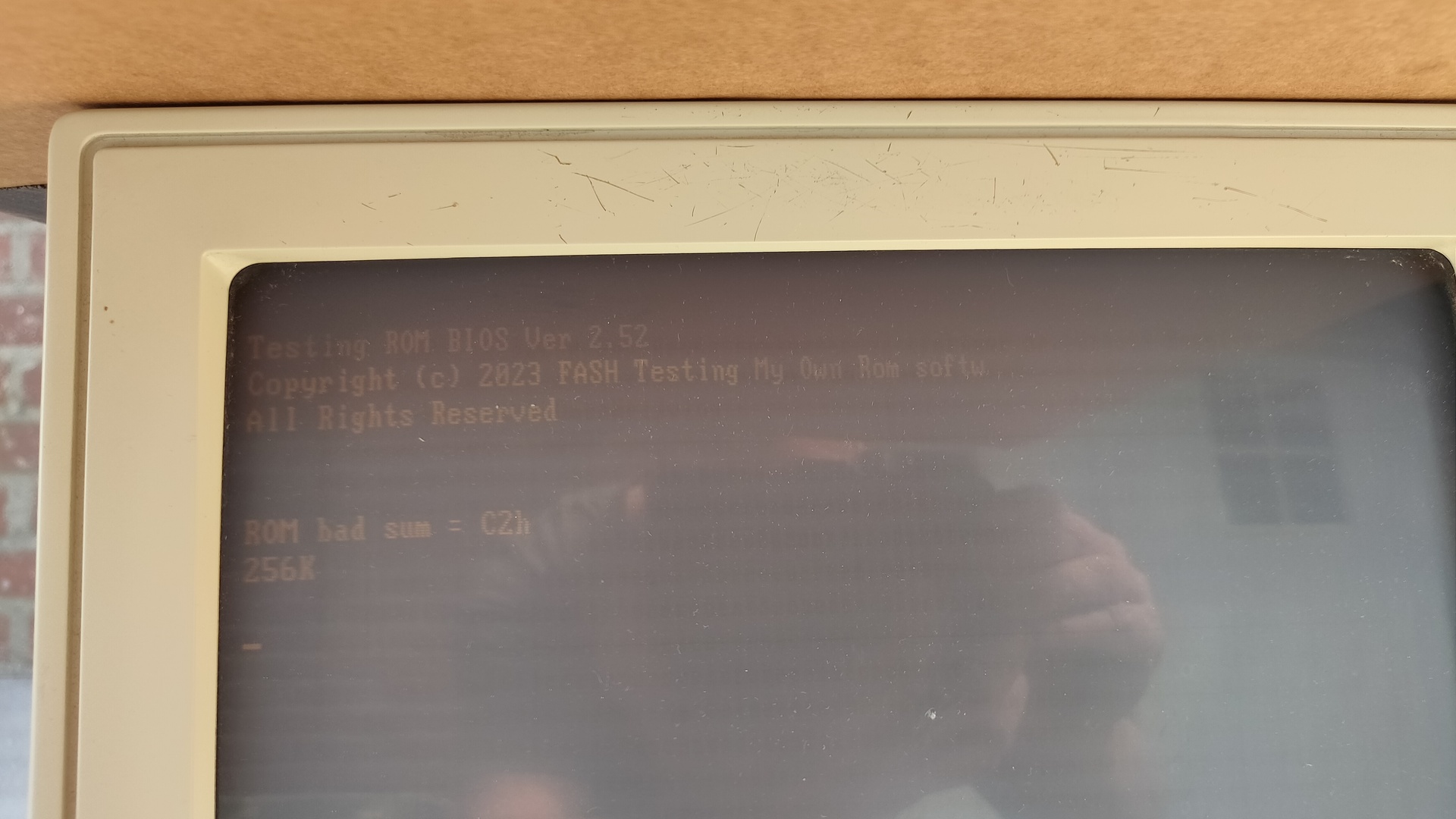
I’ve dumped the Bios to a file and used a hexeditor to play around. So that’s why there is a bad checksum.
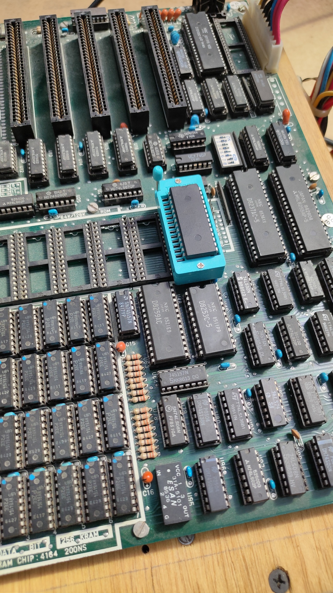
Installing a ZIF socket (Zero Insertion Force) to make things easier to modify.
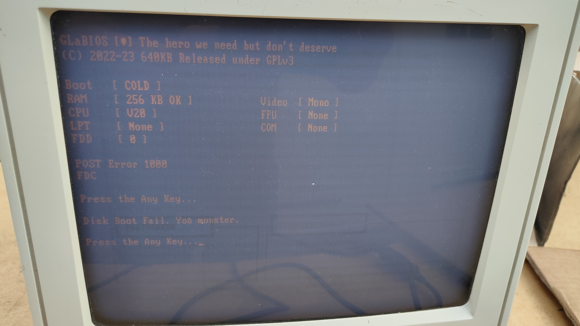
Burned GlaBios on the Eprom and now I can continue to play around.
So why? Why this all ..
I want to play around with old 8088 assembly code again, but not as I did before using a Dos machine, but hardcoded into Eproms. I’ve got 8 banks for ROMs and the source code for GlaBios is available.
In the past Edk and me wrote a boot demo, so it was not utilizing Ms-Dos functions. Maybe i can get some graphical and sound stuff working straight from the Bios.
Some commands:
# Dump the bios to file
minipro -w original.rom -p AT2764A@DIP28
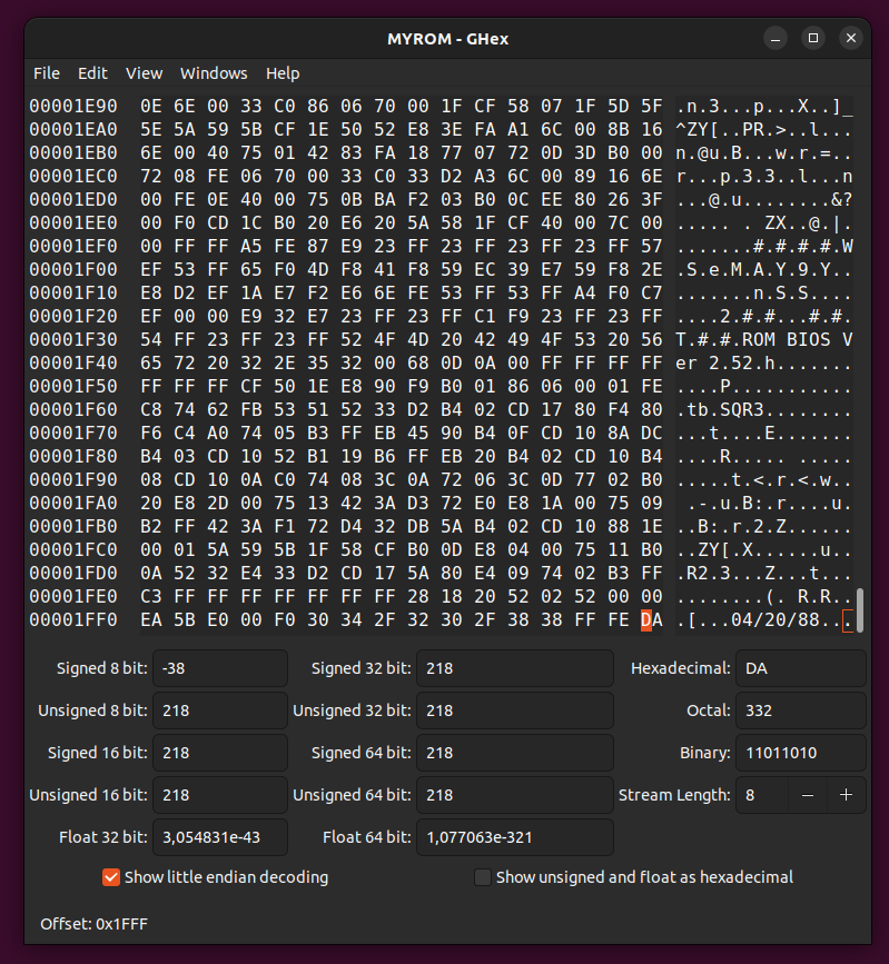
xxd and hexdump to view the dump
I've used ghex to alter the ROM
# Write a new bios to a 28C64 (same Eeprom i've used for the C64 Cartridges)
minipro -w /home/henri/Downloads/MYROM -p AT28C64
I was planning to disassemble the Phoenix Bios, but it’s quite hard to differentiate between code and data, there are no named pointers and you have to interpret every line of code.
So GlaBios it is ..
First code to look at:
This is after the whole post reset.
There is a reset pointer at ffff:fffe
Which points to the bootstrap routine, which ends in below machine code.
I'm going to plug my own code over here.

(See the funny remark about Monster as being displayed in one of above pictures)

;----------------------------------------------------------------------------;
; INT 18 - Unbootable IPL
;----------------------------------------------------------------------------;
; Display a disk boot failure message and wait for a key to cold reboot.
;
; This may be re-vectored to ROM BASIC, if present.
;
; Size: 18 bytes
;----------------------------------------------------------------------------;
INT_18 PROC
		ASSUME DS:_BDA_ABS
	PRINT_SZ  BOOT_FAIL			; print boot failure string
	XOR	AX, AX				; AH = 0 (wait for key)
	MOV	DS, AX				; DS = 0000
	MOV	WARM_FLAG_ABS, AX			; do a cold boot
	INT	16H					; wait for key press
	JMP	BOOT					; reboot
INT_18 ENDP

BOOT ENDP

;----------------------------------------------------------------------------;
;
; END OF BIOS POST/BOOTSTRAP
;
;----------------------------------------------------------------------------;

		ASSUME DS:_BDA
STRINGS PROC
;----------------------------------------------------------------------------;
; Banner Strings
;
BANNER_STRINGS PROC

					IF POST_GLADOS EQ 1
BOOT_BEGIN		DB	CR, LF
			DB	'Starting GLaDOS...'
NL2_Z			DB	LF				; two NL's, null term'd
					ENDIF
NL_Z			DB	CR, LF, 0			; one NL, null term'd
BOOT_FAIL		DB	'Disk Boot Fail.'
			DB	' You monster.'
NL2_ANY_KEY		DB	LF
NL_ANY_KEY		DB	CR, LF
ANY_KEY		DB	'Press the Any Key'
			DB	'...'
Assembly stuff
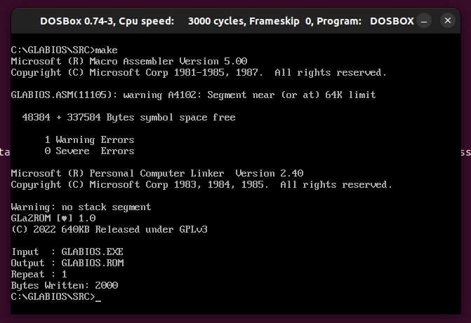
I’ve got Dosbox installed on my machine.
git clone https://github.com/640-KB/GLaBIOS.git I copied MASM.EXE and LINK.EXE in the GLaBios src directory.
edit make.bat
change MASM GLABIOS; into MASM /DVER_DATE=”05/24/23″ /DARCH_TYPE=”T” /DCPU_TYPE=”V” GLABIOS;
start dosbox
mount c: /home/henri/projects/
c:
cd glabios/src
make.bat
"If something is worth doing, it's worth overdoing."