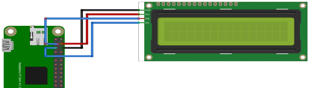
I’ve installed a headless Raspbian on a Pi Zero with a 2×16 Chars lcd display. As part of the Escape Room over the internet
Using the raspberry imager: I’ve set the username/password and ssh access in this tool. For wifi access i’ve placed below file on the SDcard in /boot (You can do this in the tool, but i want to make this dynamic when connected at a remote site.) file: wpa_supplicant.conf
sudo raspi-config
Interface options and enable I2C

sudo apt-get install python3-smbus

wget https://gist.githubusercontent.com/DenisFromHR/cc863375a6e19dce359d/raw/36b82e787450d127f5019a40e0a55b08bd43435a/RPi_I2C_driver.py
and
wget https://gist.githubusercontent.com/DenisFromHR/cc863375a6e19dce359d/raw/36b82e787450d127f5019a40e0a55b08bd43435a/examples.py

For python3 edit the example and put at the top

# requires RPi_I2C_driver.py
import RPi_I2C_driver
from time import *
unichr = chr

Run with
python3 examples.py
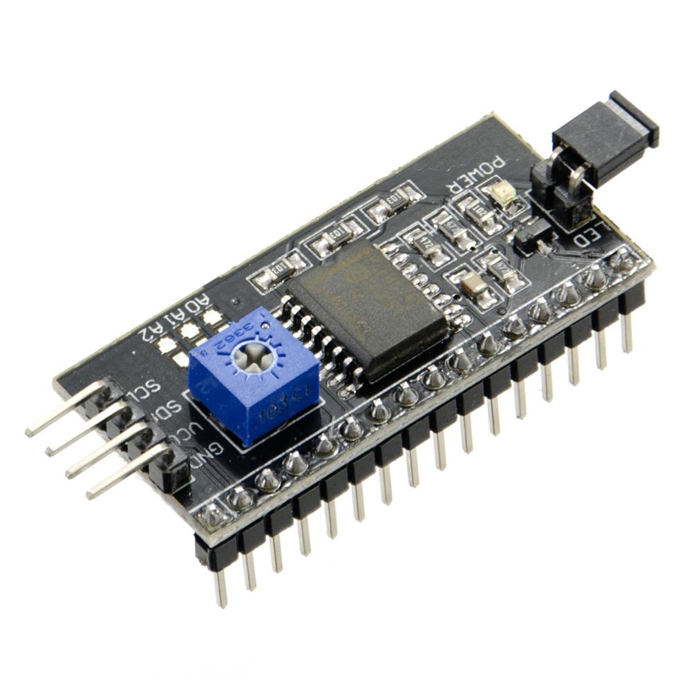
lcd display with i2c backpack
I2C backpack
Below is a mockup session.
Next todo:
Add more hardware (like buttons) to the RPI
Configure an Accesspoint on this Rpi for other devices to connect to
Install a local Mqtt broker, which connects secure to my internet facing broker
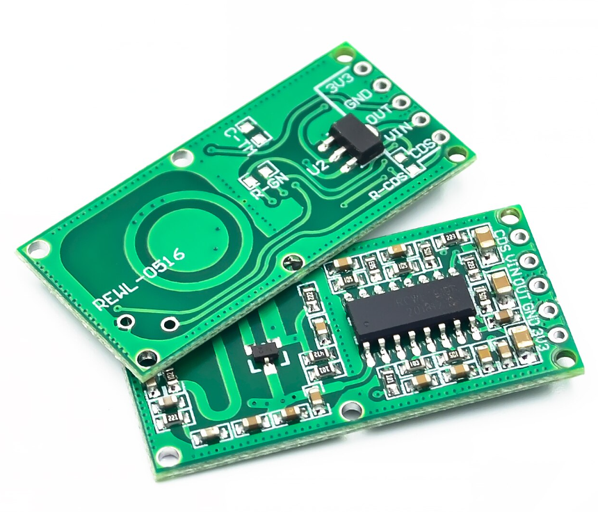
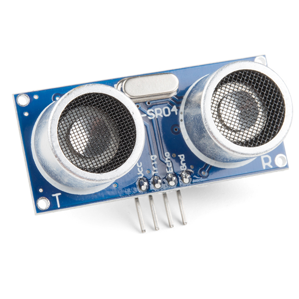
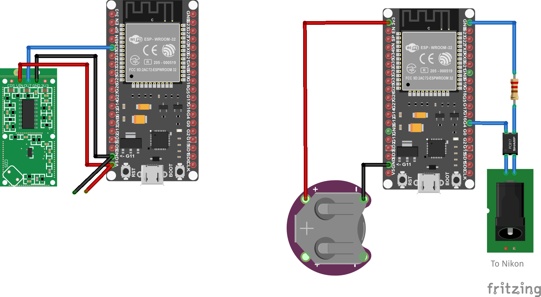
Last year i was playing with this radar module also, but today i made a version with MQTT and a linux client. (There is a project on the internet which uses a HC-SR04, and a arduino connected to the Laptop. This setup is more sensitive and no need for a usb thinghy.)
HC-SR04 module (ultrasound)
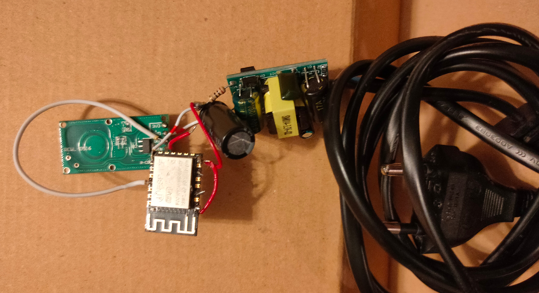
Last years version, using a micro transformer and a ESP-12
When using MQTT i can integrate this in HomeAssistant, Domoticz, NodeRed and more. But i’ve written a python script which runs on my Laptop. For example i can: Kill vlc, change to my work desktop, stop sound output and lock the screen. (everything you can script)
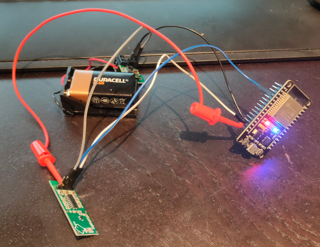
I wanted to have a “mobile” version of the sensor so i can place it anywhere. (Frontdoor, gardengate, candydrawer 🙂 )
These modules are very cheap, but do their job well!
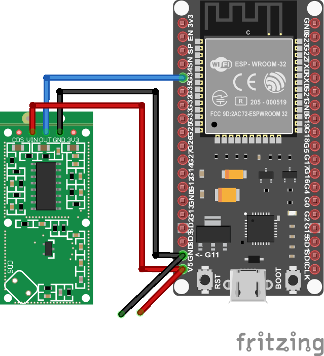
I’ve used a Wroom ESP32 and a BattBorg together with the module, that’s it.
Below shows the speed of detection, and sending though the network
Python script which does a lock-screen using XDOTOOL
from paho.mqtt import client as mqtt_client
import subprocess
import time

broker = 'MQTT-SERVER'
port = 1883
topic = "radar/state"
client_id = "radarclient"

def connect_mqtt() -> mqtt_client:
    def on_connect(client, userdata, flags, rc):
        if rc == 0:
            print("Connected to MQTT Broker!")
        else:
            print("Failed to connect, return code %d\n", rc)

    client = mqtt_client.Client(client_id)
    client.on_connect = on_connect
    client.connect(broker, port)
    return client

def subscribe(client: mqtt_client):
    def on_message(client, userdata, msg):
        state = msg.payload.decode()
        print (state)
        if state == "1":
            subprocess.Popen(["xdotool","key","Super_L+l"])
            time.sleep(30)


    client.subscribe(topic)
    client.on_message = on_message

def run():
    client = connect_mqtt()
    subscribe(client)
    client.loop_forever()

if __name__ == '__main__':
    run()
change subprocess.Popen([“xdotool”,”key”,”Super_L+l”]) into subprocess.Popen([“switchdesktop”]) to run a script named switchdesktop
#!/bin/bash
# This is the switchdesktop script, it goes to the next screen using winows-page-down combo
xdotool key "Super_L+Page_Down"
Todo:
3D print a case Make a version which becomes a Access Point. Then make another arduino setup which controls my Nikon. So it can act like a wildcam (offline)
Something like below, using a optocoupler ( i still got some leftovers from my doorbell to gpio-pin project.)
The goal of this project is to have a raspberry-pi with a screen wich shows network information. It wil be using a battery, touchscreen .. maybe some status leds. When debugging network issues we want to have information when/if/how a network port works on our switches.
It should show:
dhcp ip
gateway
can access internet?
speedtest
detect if vlan tagged network packets are present on the port?
icmp test
list of detected nearby hosts?
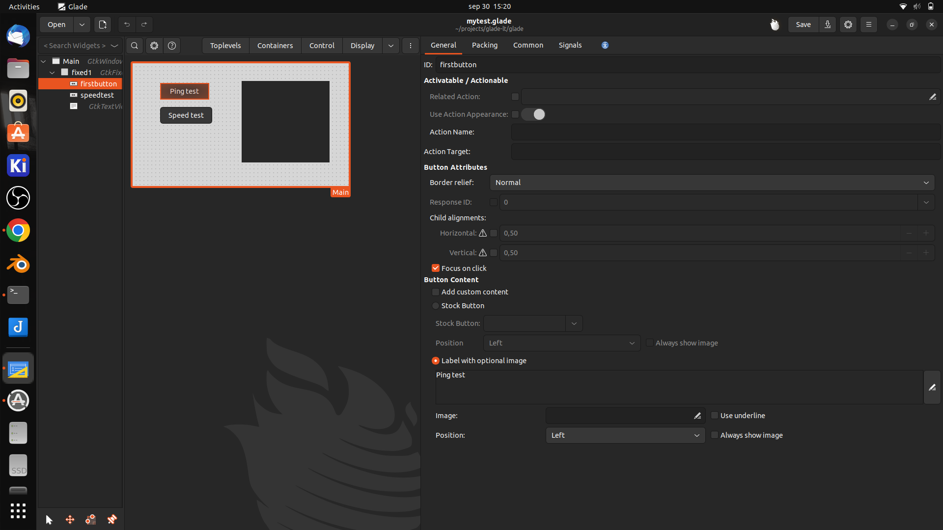
A long time ago i played with glade and C / Perl.
But i’d rather use python so i’m looking into glade/python combi for this little project.
Glade is a gnome/GTK user interface RAD tool. (Rapid Application Development)
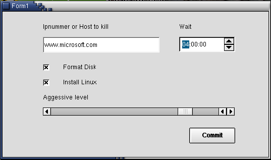
i’ve used zenity and yad before to create simple gui’s for bash scripts, these where only for quick and dirty solutions. (See other posts) Glade is a far better solution, but a little harder to use.
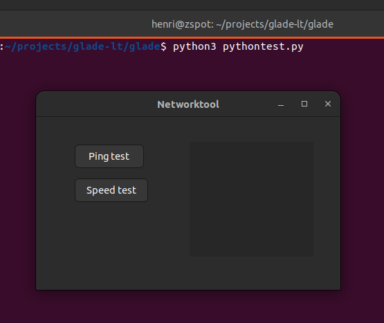
Below is a little framework i started with
Python script
import gi

gi.require_version("Gtk", "3.0")
from gi.repository import Gtk

class Handler:
    def onDestroy(self, *args):
        Gtk.main_quit()

    def on_firstbutton_clicked(self, button):
        print("Ping test")

builder = Gtk.Builder()
builder.add_from_file("mytest.glade")
builder.connect_signals(Handler())

window = builder.get_object("Main")
window.show_all()

Gtk.main()
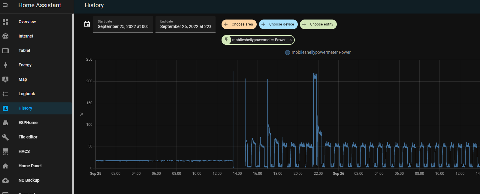
Having a lot of devices and running a Lab wil use a lot of energy. Now with the energy crisis in Europe, i had to take a closer look at whats using power in my house.
I notished some weird usage patterns while measuring.
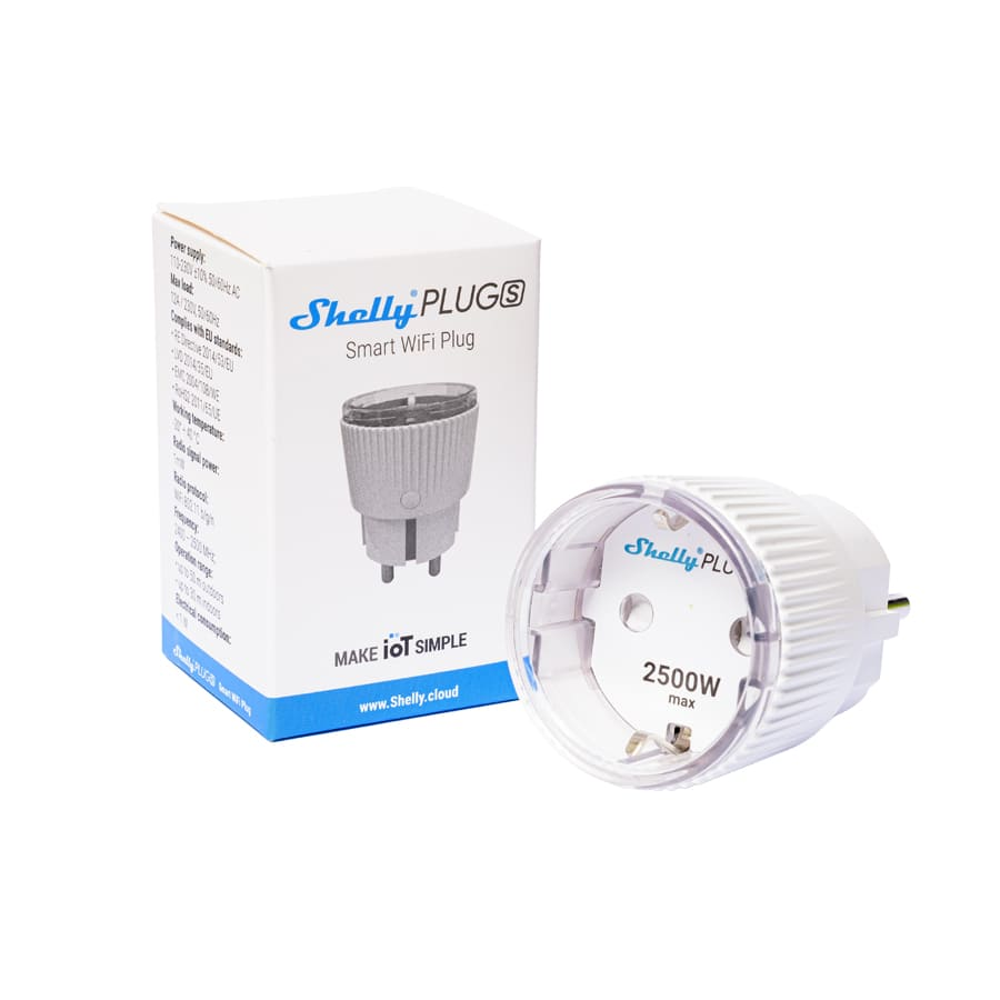
I’m using a few shelly power plugs, to measure devices and powerstrips.
With these devices you can control devices connected to it. On/Off/Timer etcetera. It wil measure the power usage in watts, and it even got a temperature sensor. I like the fact that it perfectly integrates into your home automation using an extensive API. curl commands to controll, and even MQTT messaging. Intergrating in Home Assistant is a breeze.
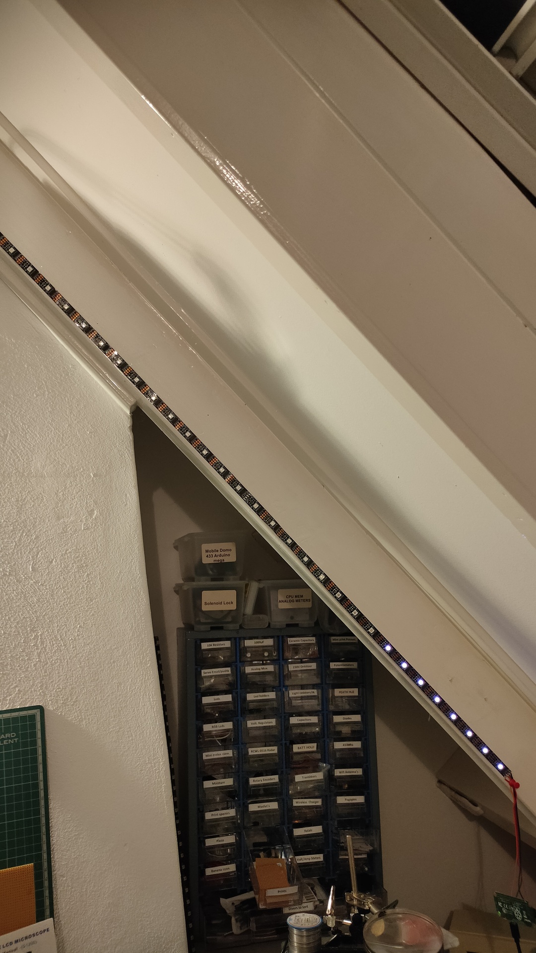
So i was monitoring a bunch of stuff using Nodered/Grafana/Homeassistant and saw some recurring usage. But being always late to check things, i made use of my ledserver i’ve build a long time ago.
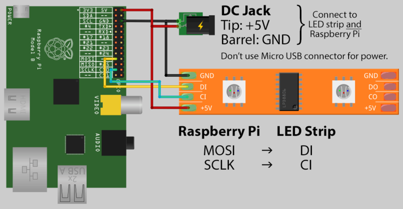
This ledserver consists of a Raspberry Pi Zero, with a led string and a API written in python.
Below is autostarted on the Raspberry
( I made this ledserver for work, it showed the status of servers and services. Beside that every colleage had a range which he could use for his own scripts. I made some little bash script templates to have led funtions standard in your bash profile.
#!/usr/bin/python


# apt-get install python-flask
#

import Adafruit_WS2801
import Adafruit_GPIO.SPI as SPI
import struct

from flask import Flask, render_template, request
app = Flask(__name__)

PIXEL_COUNT = 32
SPI_PORT   = 0
SPI_DEVICE = 0

pixels = Adafruit_WS2801.WS2801Pixels(PIXEL_COUNT, spi=SPI.SpiDev(SPI_PORT, SPI_DEVICE))

pixels.clear()
pixels.show()

@app.route("/led/<deviceName>/<color>")
def action(deviceName, color):
        if deviceName == 'reset':
                print ("reset")
                pixels.clear()
        print (deviceName)
        led = int(deviceName)
        s = color
        r = int(s[ :2], 16)
        b = int(s[2:4], 16)
        g = int(s[4: ], 16)

        pixels.set_pixel_rgb(led, r,g,b)
        pixels.show()

        templateData = {
                'rled'  : r,
                'bled'  : b,
                'gled'  : g,
                'deviceName'  : deviceName,
        }
        return render_template('index.html', **templateData)

@app.route("/control/<controlcommand>")
def actioncommand(controlcommand):
        if controlcommand == 'clear':

                print("clear")
                pixels.clear()
                pixels.show()

        templateData = {
                'controlcommand'  : controlcommand,
        }
        return render_template('index.html', **templateData)

@app.route("/range/<start>/<stop>/<color>")
def rangecommand(start,stop,color):
        s = color
        r = int(s[ :2], 16)
        b = int(s[2:4], 16)
        g = int(s[4: ], 16)
        startled = int(start)
        stopled = int(stop)
        while (startled < stopled):
          pixels.set_pixel_rgb(startled, r,g,b)
          startled=startled + 1
        pixels.show()

        templateData = {
                'rangecommand'  : rangecommand,
        }


        return render_template('index.html', **templateData)


if __name__ == "__main__":
   app.run(host='0.0.0.0', port=8080, debug=True)
Now you can control the leds with a simple curl command:
So today i made a little script to show power usage.
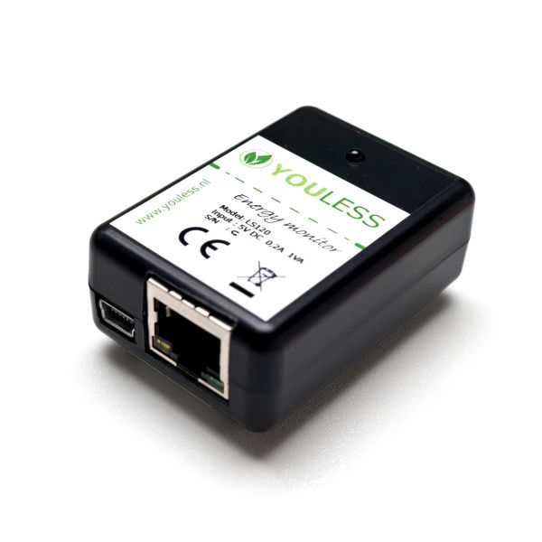
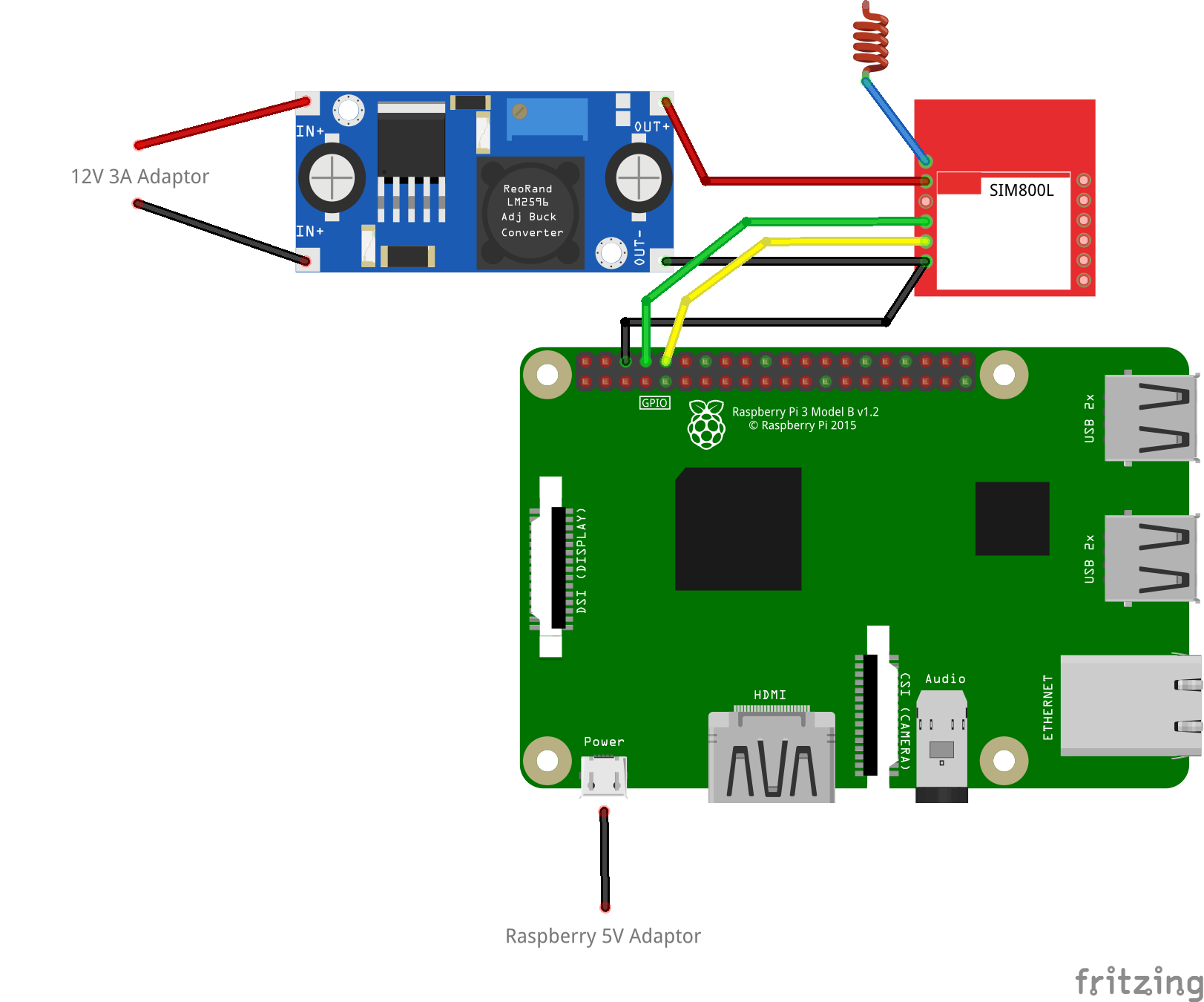
I’m reading the current power usage from a LS120 Youless
Youless LS120 device, which you can connect to your P1 connector.
With below bash script i’m reading the webinterface and update the ledstring. I was using this ledserver for general notification usage. Below a 2 minute hack ..
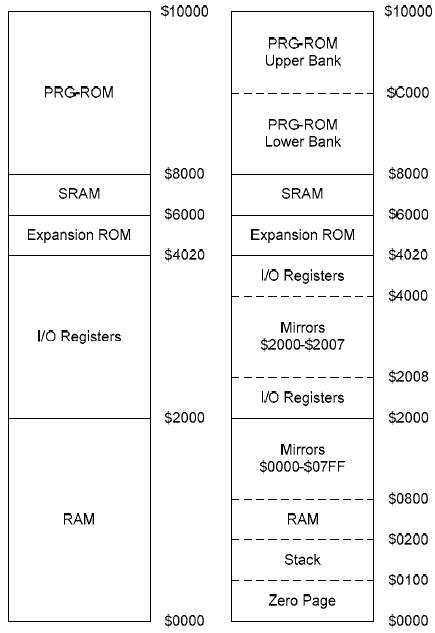
Started to write a program to generate a memory map like this
It will be a python script which generates a ascii table.
| a15 | a14 | a13 | a12 | a11 | a10 | a09 | a08 | a07 | a06 | a05 | a04 | a03 | a02 | a01 | a00 |
|  1  |  a  |  a  |  a  |  a  |  a  |  a  |  a  |  a  |  a  |  a  |  a  |  a  |  a  |  a  |  a  | ROM
|  0  |  0  |  a  |  a  |  a  |  a  |  a  |  a  |  a  |  a  |  a  |  a  |  a  |  a  |  a  |  a  | RAM
|  0  |  1  |  1  |  x  |  x  |  x  |  x  |  x  |  x  |  x  |  x  |  x  |  a  |  a  |  a  |  a  | VIA
|  0  |  0  |  0  |  0  |  0  |  0  |  0  |  1  |  a  |  a  |  a  |  a  |  a  |  a  |  a  |  a  | PS
Above example shows:
Rom – $8000 and up
Ram – $0000 till $3FFF
Via chip – $6xxx-$7xxxx 16 addresses repeating in this block. This will be the interesting/hard part
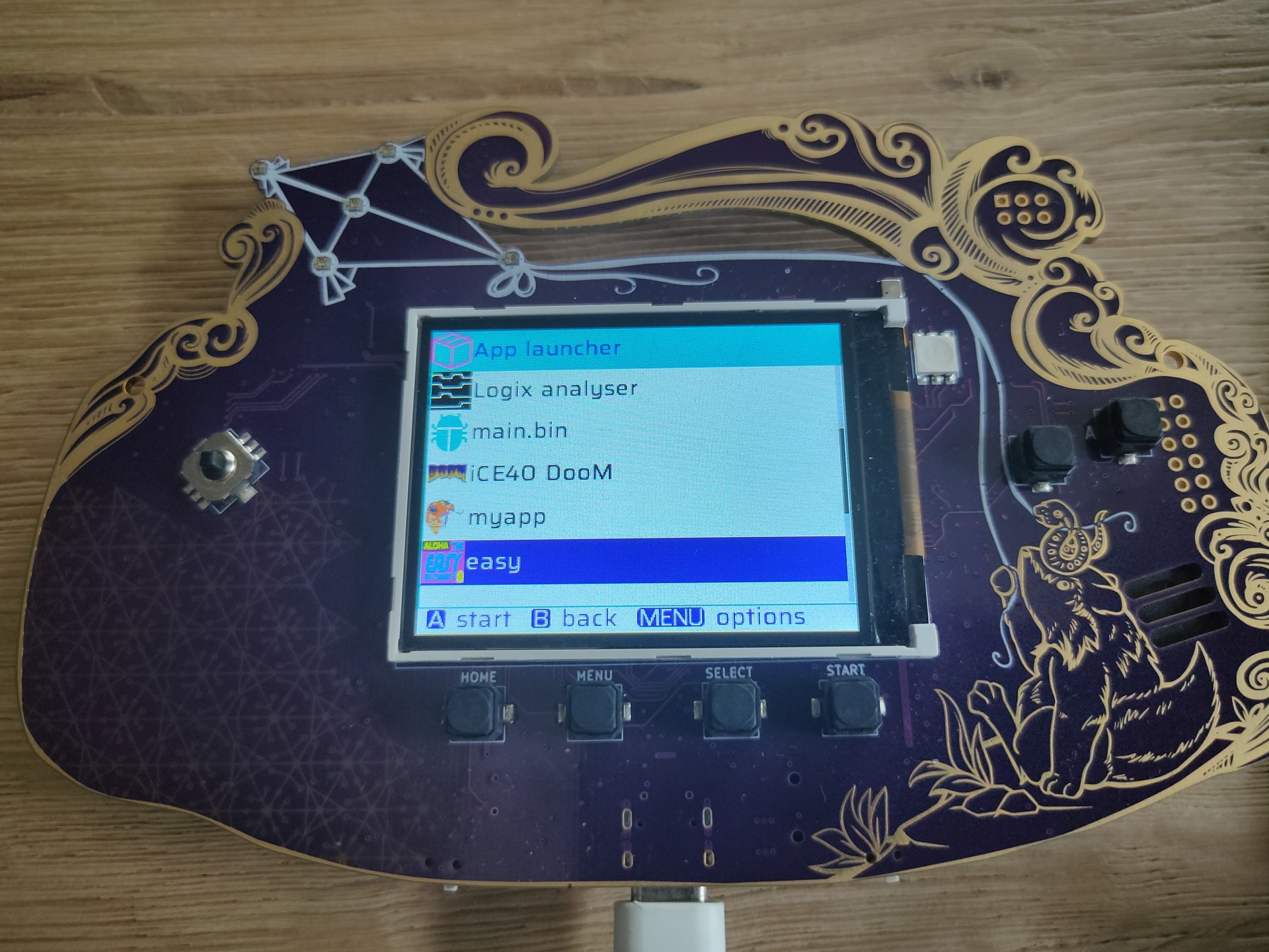
python mch2022-tools/webusb_fat_dir.py /flash/apps/python/easy
for f in easy.mp3 easy.png icon.png __init__.py ; do python  mch2022-tools/webusb_fat_push.py $f /flash/apps/python/easy/$f ; done
Micropython code __init__.py
mport display
import mch22
from audio import play
import buttons
from time import sleep
from machine import Pin
from neopixel import NeoPixel

powerPin = Pin(19, Pin.OUT)
dataPin = Pin(5, Pin.OUT)
np = NeoPixel(dataPin, 5)
powerPin.on()


def on_home_btn(pressed):
  if pressed:
    mch22.exit_python()


display.drawPng(0,0,"/apps/python/easy/easy.png")
display.flush()


# Led setup
#   2   3
#      1
#     0     4

np[0] = (23,5,15)
np[1] = (3,15,22)
np[2] = (25,24,1)
np[3] = (25,24,1)
np[4] = (23,4,15)
np.write()


buttons.attach(buttons.BTN_HOME, on_home_btn)
# playing with volume 0 to wakeup sound device, else it is going to clip
play('/apps/python/easy/easy.mp3', volume=0)
sleep(7)
while True:
    play('/apps/python/easy/easy.mp3', volume=100)
    sleep(30)
App with iconLed in aloha colors and aloha sound clip every 30s
Download from https://micropython.org/resources/firmware/esp32-20220618-v1.19.1.bin
Test with
screen /dev/ttyUSB0 115200
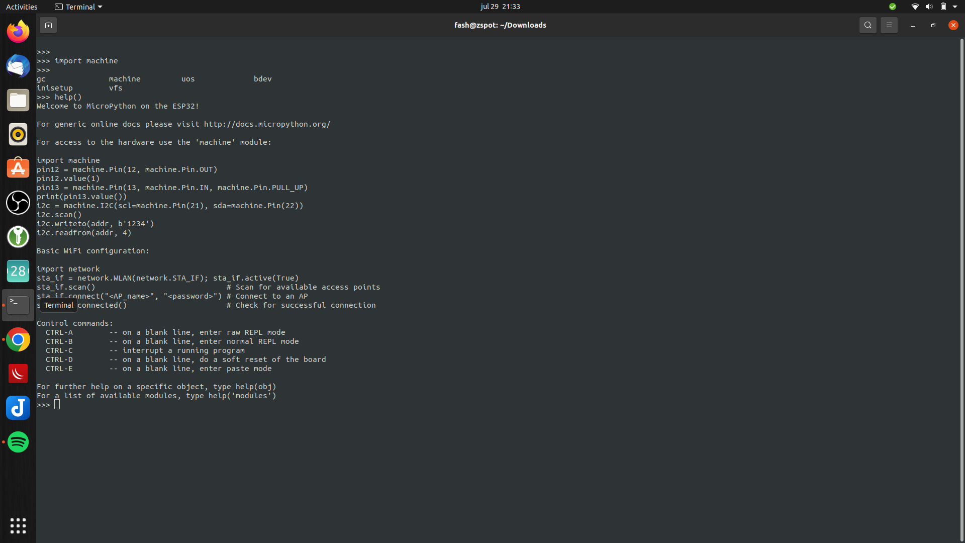
Enter import machine or help()
Great up and running
Now we have to install a boot loader Use ampy to list files
#list boot
ampy -p /dev/ttyUSB0 ls
/boot.py

#get boot.py
ampy -p /dev/ttyUSB0 get boot.py
vi boot.py (create new)
#import esp
#esp.osdebug(None)
#import webrepl
#webrepl.start()

def connect():
    import network
    sta_if = network.WLAN(network.STA_IF)
    if not sta_if.isconnected():
        print('connecting to network...')
        sta_if.active(True)
        sta_if.connect('WIFISSID', 'WIFIPASS')
        while not sta_if.isconnected():
            pass
    print('network config:', sta_if.ifconfig())
Push the file
ampy -p /dev/ttyUSB0 put boot.py
Usage: ampy [OPTIONS] COMMAND [ARGS]...

  ampy - Adafruit MicroPython Tool

  Ampy is a tool to control MicroPython boards over a serial connection.
  Using ampy you can manipulate files on the board's internal filesystem and
  even run scripts.

Options:
  -p, --port PORT    Name of serial port for connected board.  Can optionally
                     specify with AMPY_PORT environment variable.  [required]
  -b, --baud BAUD    Baud rate for the serial connection (default 115200).
                     Can optionally specify with AMPY_BAUD environment
                     variable.
  -d, --delay DELAY  Delay in seconds before entering RAW MODE (default 0).
                     Can optionally specify with AMPY_DELAY environment
                     variable.
  --version          Show the version and exit.
  --help             Show this message and exit.

Commands:
  get    Retrieve a file from the board.
  ls     List contents of a directory on the board.
  mkdir  Create a directory on the board.
  put    Put a file or folder and its contents on the board.
  reset  Perform soft reset/reboot of the board.
  rm     Remove a file from the board.
  rmdir  Forcefully remove a folder and all its children from the board.
  run    Run a script and print its output.
Connect to serial console using screen
sudo screen /dev/ttyUSB0 115200
(use CTRL-A \ to exit)
Connect to wifi
import boot
connect()
Led blinky test, with below file named ledtest.py
import time
from machine import Pin
led=Pin(2,Pin.OUT)        #Internal led pin

while True:
  led.value(1)            #Set led turn on
  time.sleep(0.5)
  led.value(0)            #Set led turn off
  time.sleep(0.5)
Upload and run script
ampy -p /dev/ttyUSB0 put ledtest.py
import ledtest (without .py!)
Next todo: boot.py @boot ?!? Run custom python after booting. Connect display and play with drawing.
Tip: Install rshell !
sudo pip3 install rshell
fash@zspot:~$ rshell
Welcome to rshell. Use Control-D (or the exit command) to exit rshell.

No MicroPython boards connected - use the connect command to add one

/home/fash> autoconnect: /dev/ttyUSB0 action: add

/home/fash> ?

Documented commands (type help <topic>):
========================================
args    cat  connect  date  edit  filesize  help  mkdir  rm     shell
boards  cd   cp       echo  exit  filetype  ls    repl   rsync

Use Control-D (or the exit command) to exit rshell.
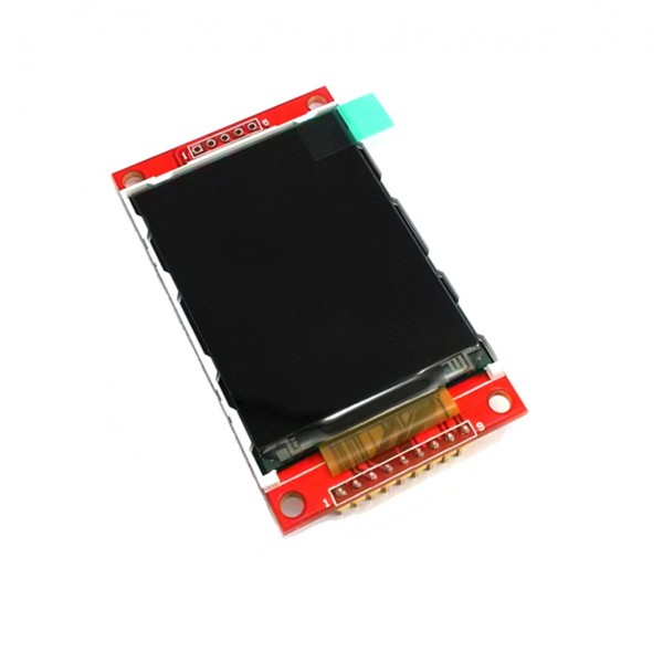
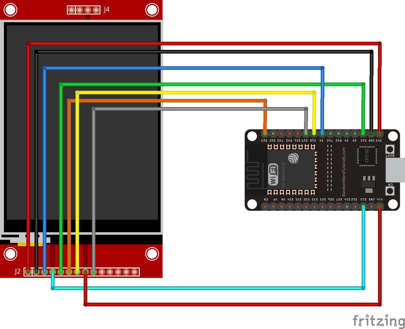
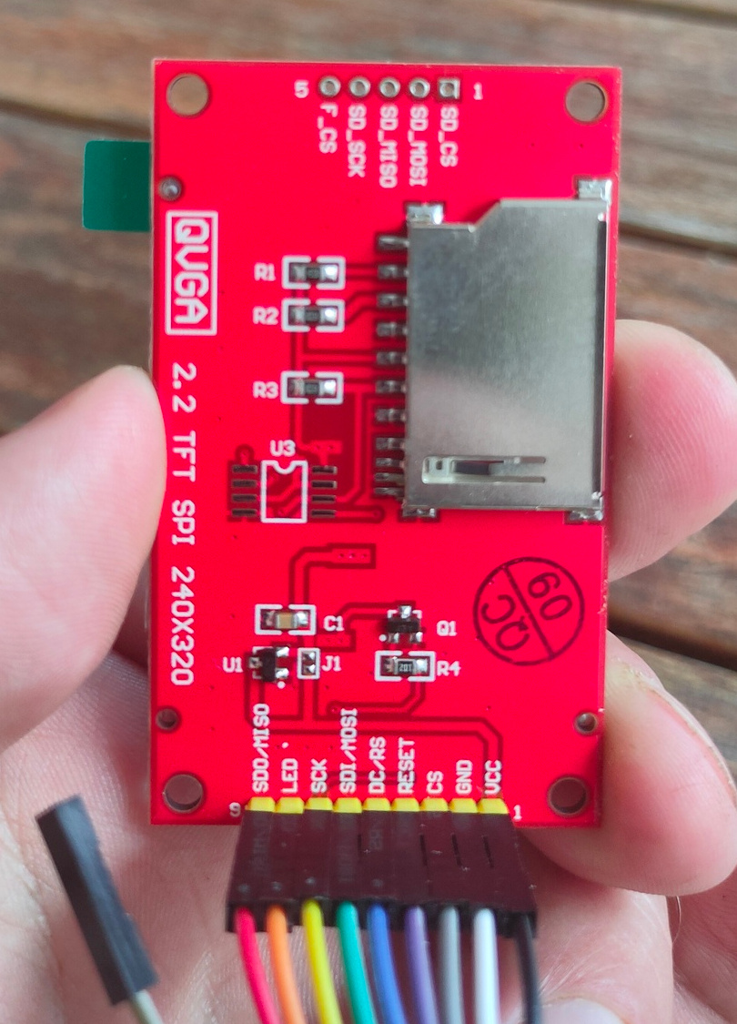
Connecting the display
I’ve connected the display as above. Note the different connections on the display. Above fritzing part has connections for touch screen! The 4 or 5 pins on the other side are for sdcard functionallity.
Now you can use the library by editing a example like demo_bouncing_boxes.py
Add and change
# At the beginning of the file
import setupmydisplay.py

Futher down comment two lines and add your own setup

        # Baud rate of 40000000 seems about the max
        #spi = SPI(1, baudrate=40000000, sck=Pin(14), mosi=Pin(13))
        #display = Display(spi, dc=Pin(4), cs=Pin(16), rst=Pin(17))
        display = setup.createMyDisplay()
Upload to ESP32 and testing!
ampy -p /dev/ttyUSB0 put demo_bouncing_boxes.py
ampy -p /dev/ttyUSB0 put setupmydisplay.py
# connect and start
sudo screen /dev/ttyUSB0 115200
import demo_bouncing_boxes.py
Almost … friday will be the day i’ll attend May Contain Hackers. Besides the awesome villages and talks.
UPDATE: 20220727 UPDATE: 20220812
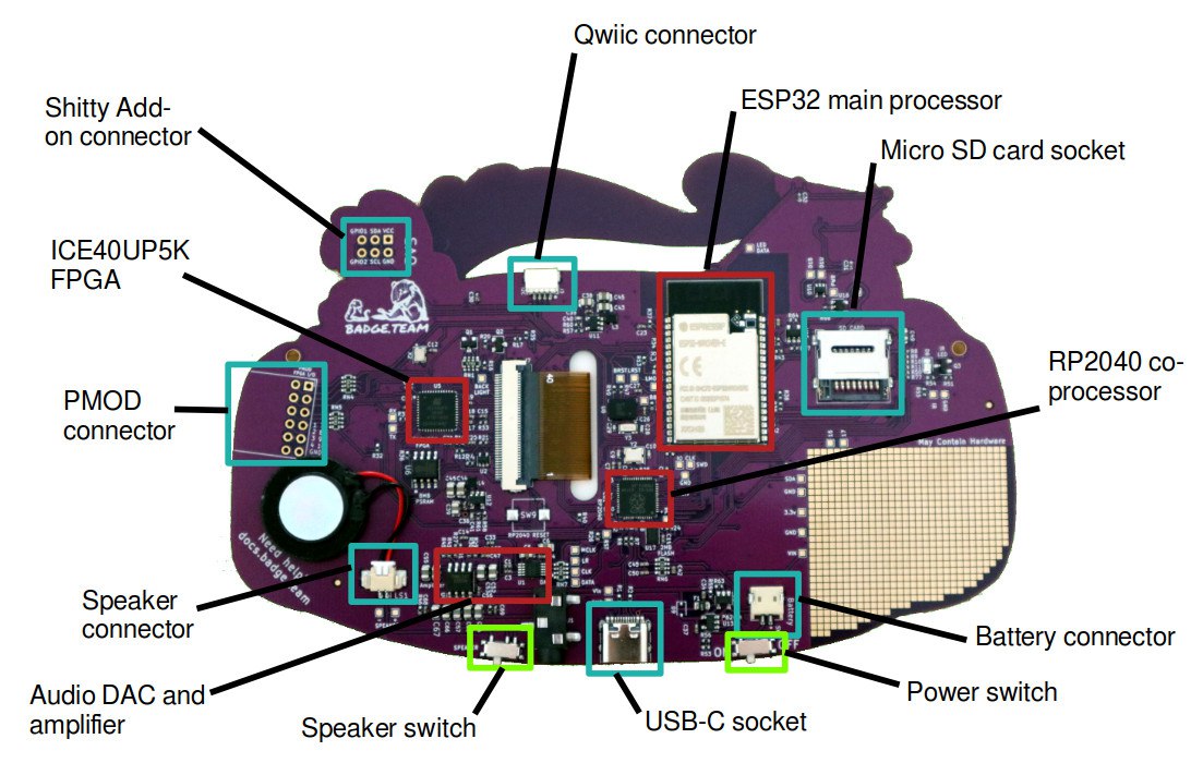
You get a hackable badge, this one is more amazing as previous versions.
I can’t wait to have a go at this cool gadget. I personally could do without the pcb fancy design.
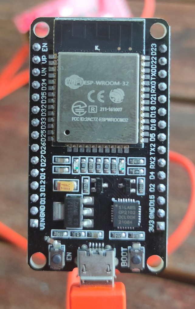
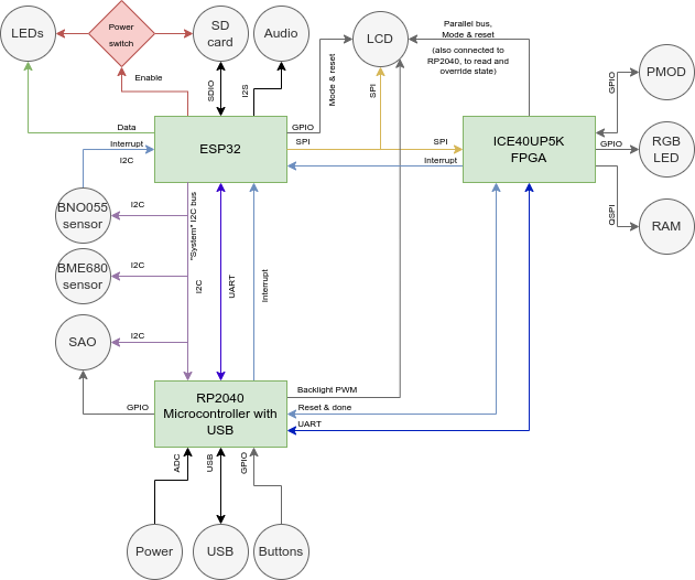
Espressif ESP32 Wrover-E with 16MB of flash storage and paired with 8MB of PSRAM, for front-end badge computing and compatibility with the badge.team ecosystem back to the 2017 SHA badge.
Lattice ICE40UP5K FPGA for hardware-accelerated graphics and user FPGA hardware designs.
Raspberry Pi RP2040 for advanced USB communication and board management.
2Ah LiPo battery to give you a full day of fun on a charge.
16-bit DAC with stereo output to headphone socket, onboard mono speaker.
ILI9341 2.2 inch TFT display with a 240 by 320 pixel resolution.
Bosch BNO055 orientation sensor.
Bosch BME680 environmental sensor.
The usual array of addressable LEDs.
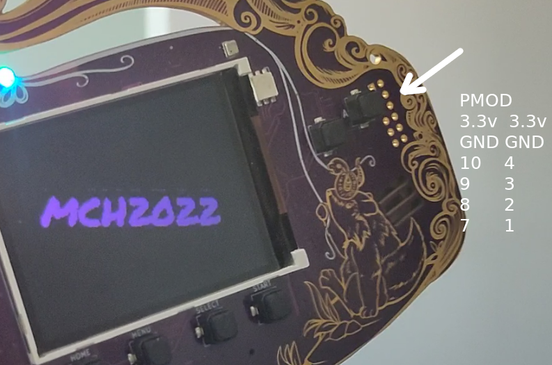
SAO and Qwiic expansion connectors, FPGA PMOD expansion, plus onboard prototyping area.
Downloadable apps, micro python, Arduino ide programming. All kinds of GPIO pins, leds buttons, sound. Check out https://hatchery.badge.team/
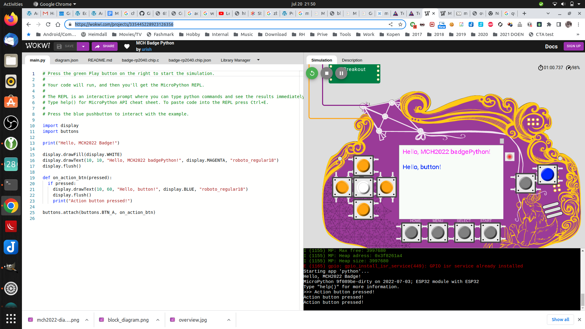
You can play with this virtually here! https://wokwi.com/projects/335445228923126356
So much potential! Great start for a DIY project.
I won’t post about the workings, thats all well documented online. I shall post about the hacks/findings i personally did.
UPDATE: 20220727 Made a micropython program to keep your NameTag level to the ground (Better version)
UPDATE: 20220812
Someone made a 8bit logic analyser using the pmod connector !