There are a lot of old develop boards for all kinds for cpu’s.
These where build to learn machine code programming. Mostly made in the 80’s, and based on populair cpu’s at that time.
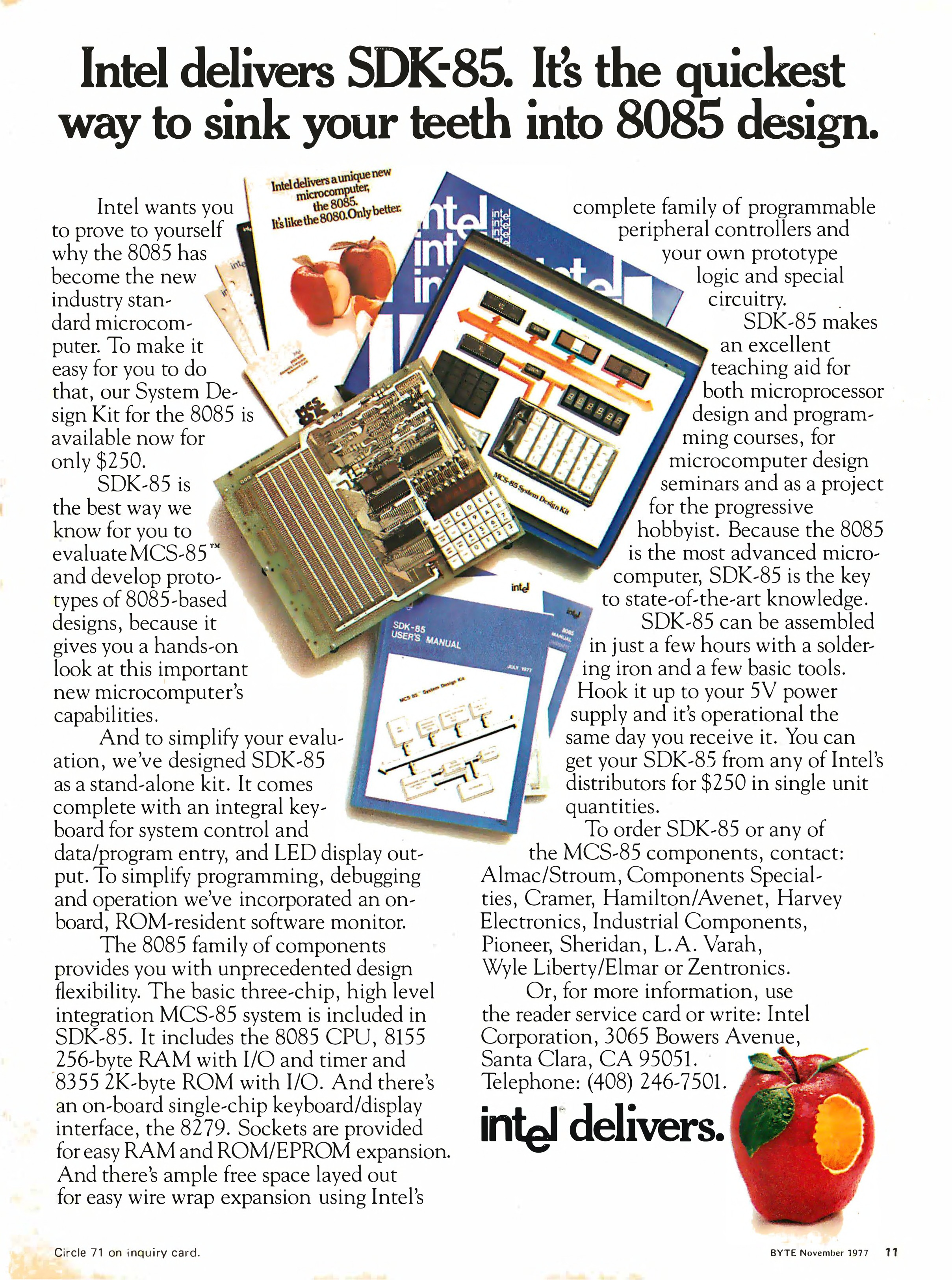
I own a some of these SDK’s (System Design Kits)
8085 – SDK85 i bought recently 8085 CPU
Microprofessor-1 (MPF-1) Z80 CPU
And my own 680x based computer
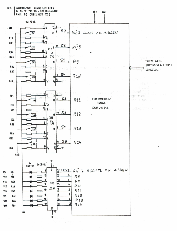
Most of these use a keyboard scanner which is also connected to 7 segment displays.
The way they work is practically the same. There is a VIA or PIA. Versitile interface adaptor, or Peripheral interface adaptor. These have two times 8 bits to control devices. When using 4 bits and convert these to 16 lines by using a 75ls145 for example. If you put a counter on those 4 bits, you sequently activate 1 of 16 lines. These lines you can use to scan a keyboard matrix OR display a character on a 7 segment display. These display’s won’t hold the data (and show the character) when not activated. The trick is to update de display fast enough so you don’t see the flickering on/off.
Activate a line and read a byte with the VIA = Reading keyboard row Activate a line and write a byte with the VIA = Display on a segment
These VIA/PIA’s where made with specific timings to match the CPU. 6522/6820/8255
Below you see some different implementations of these keyboard/display combo’s
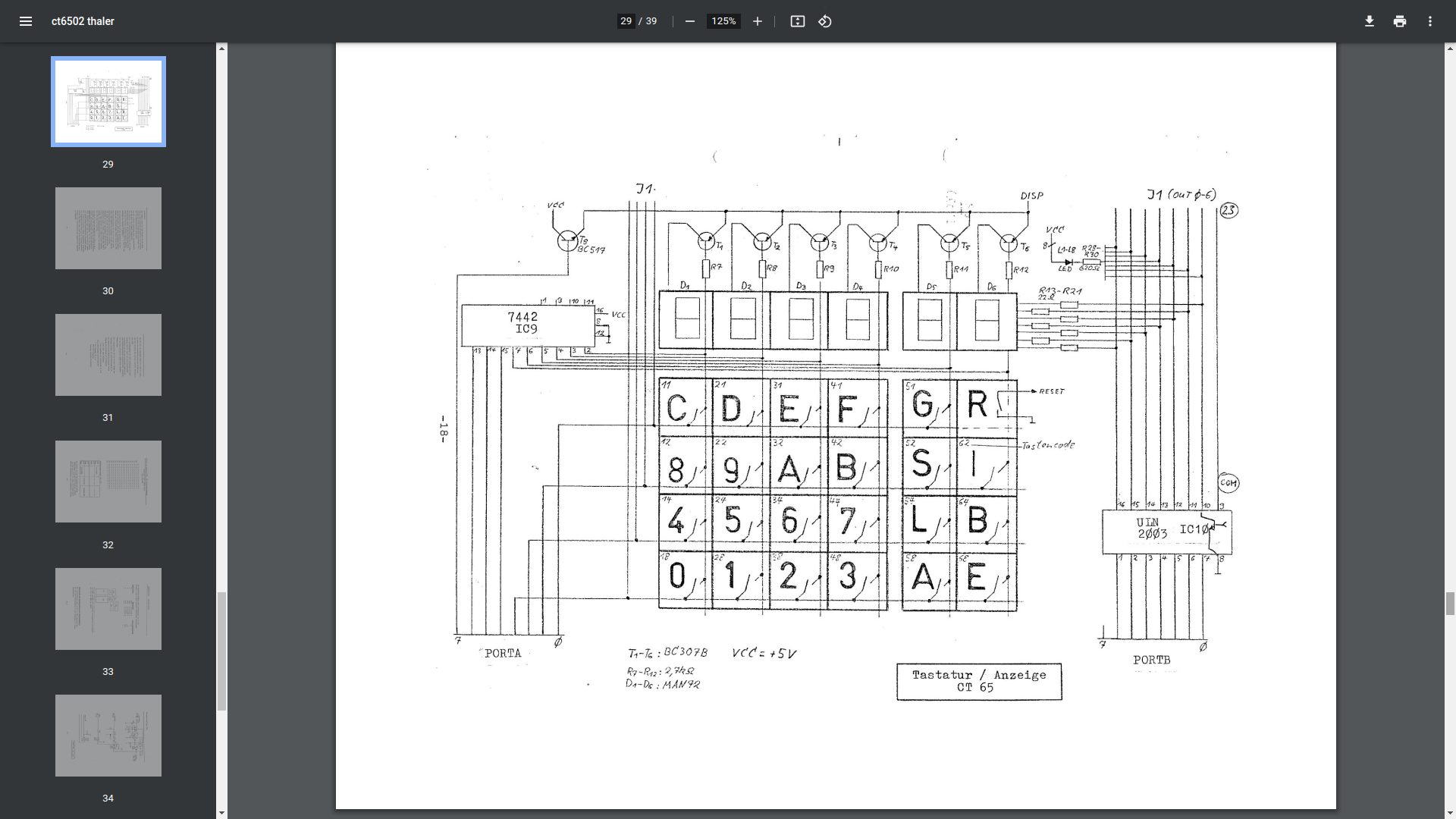
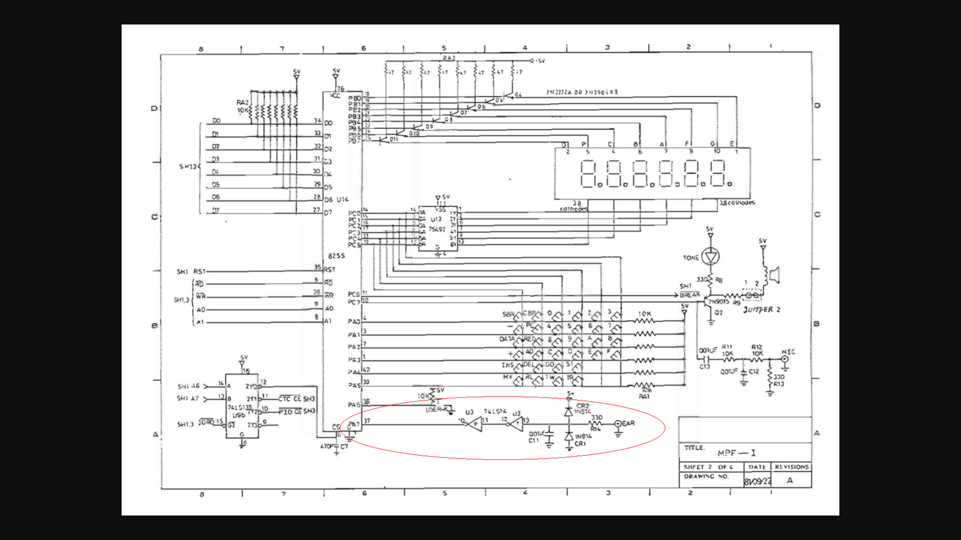
Thaler 6502 kit
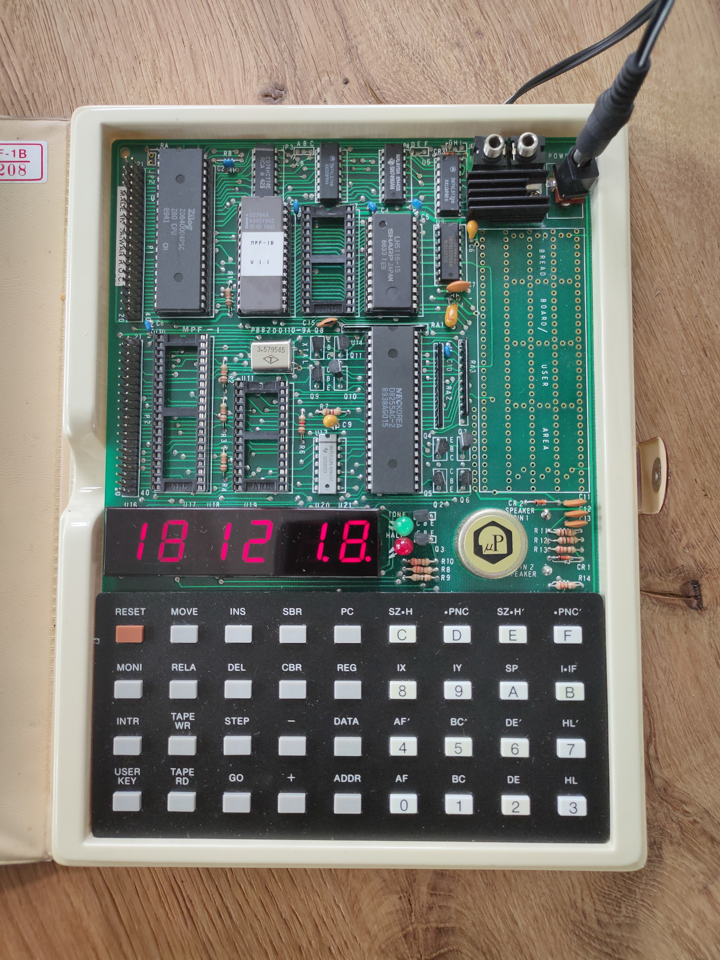
Microprofessor MPF-1 kit (ignore red circle)
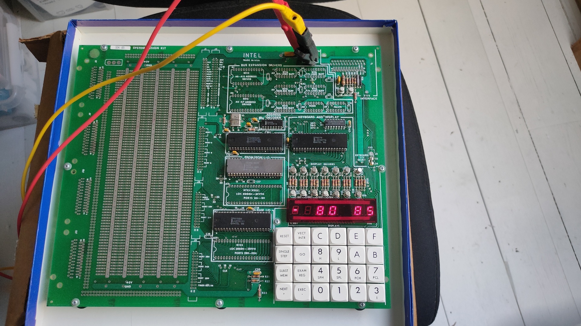
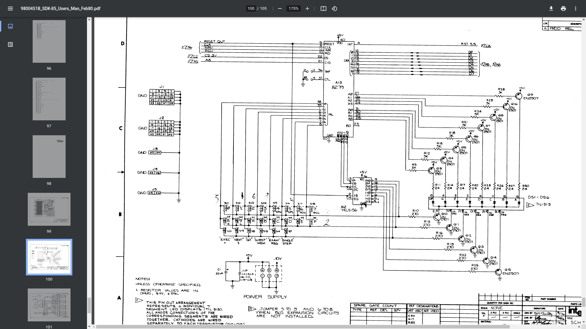
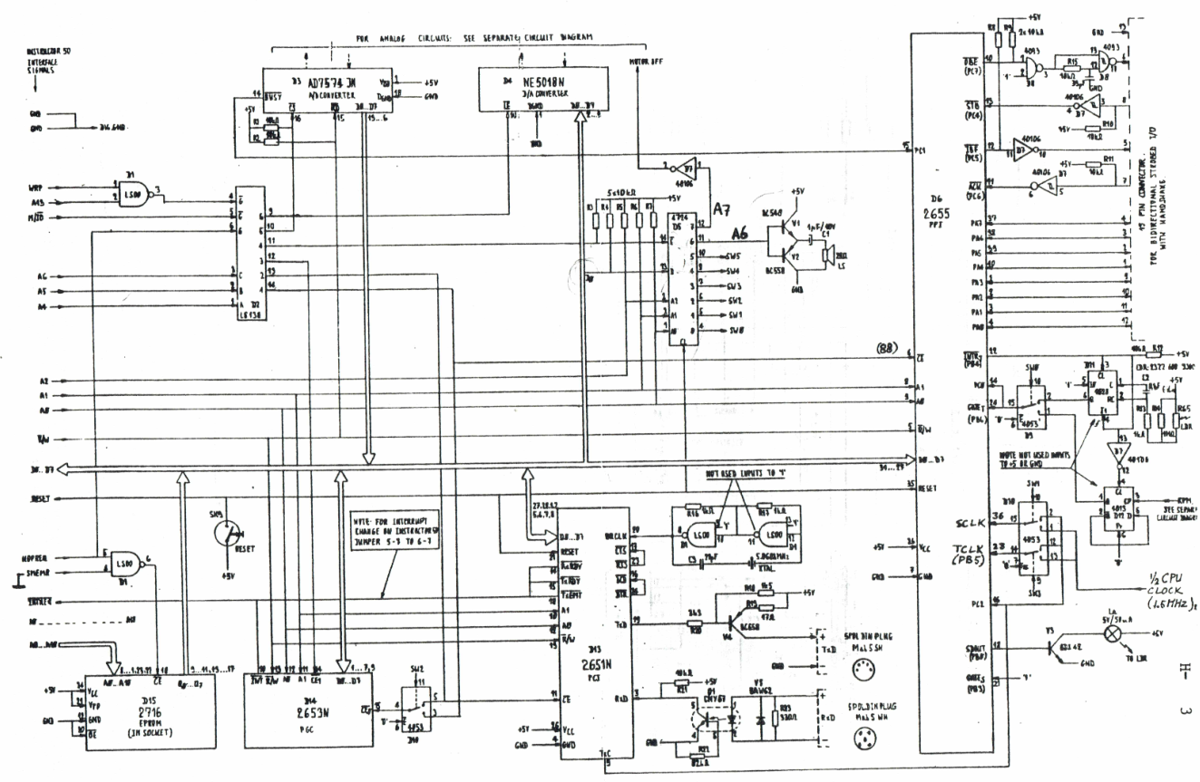
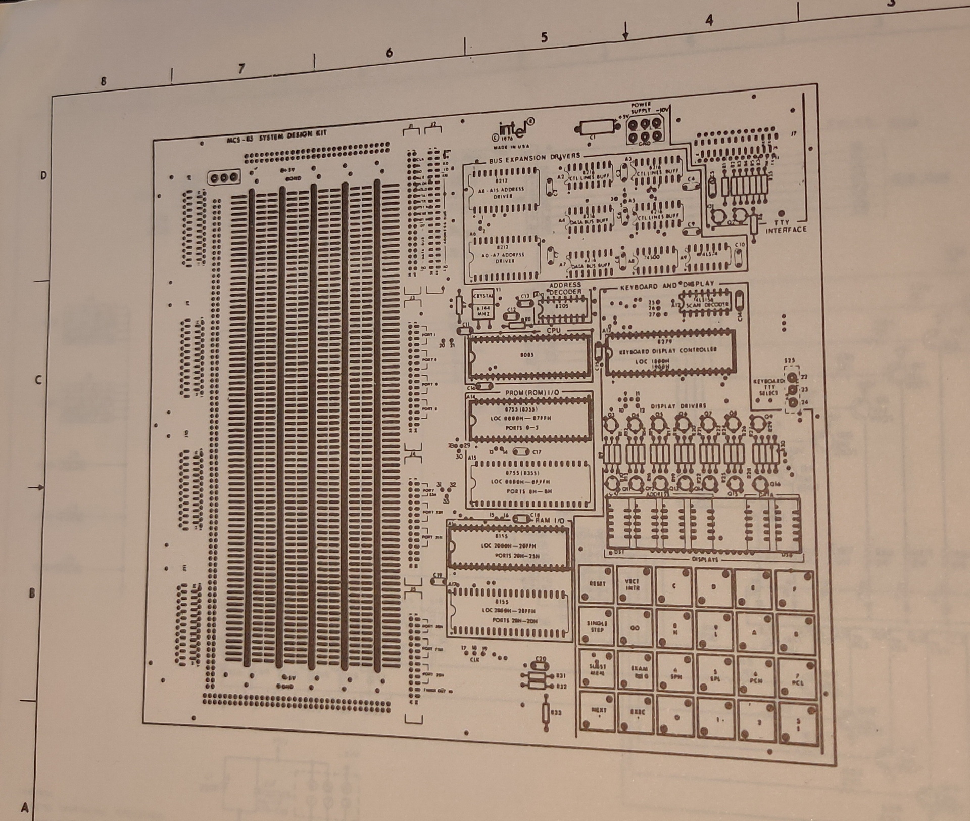
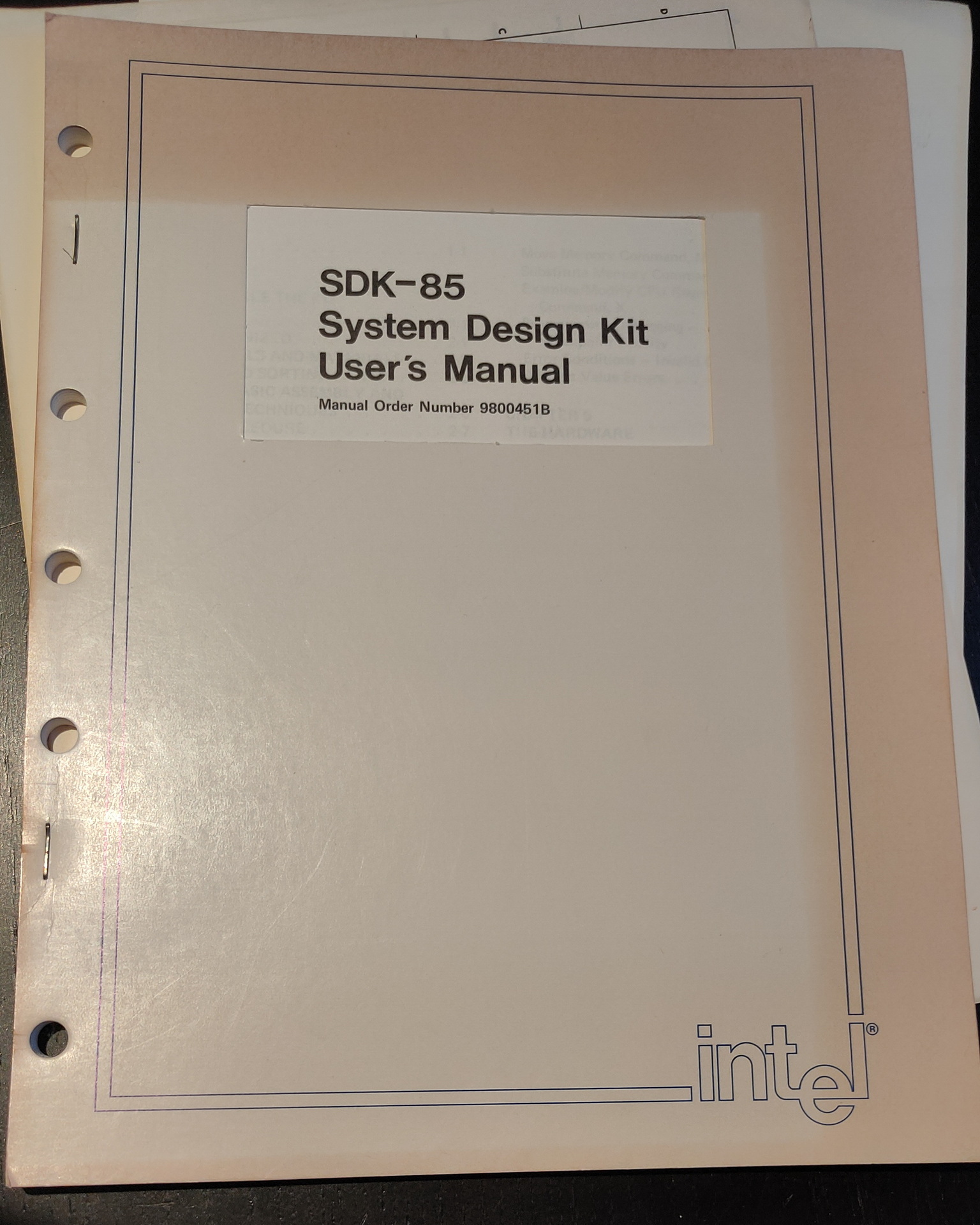
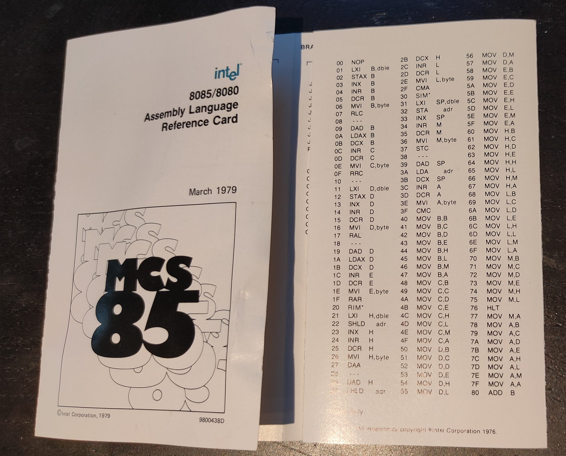
SDK85 kit
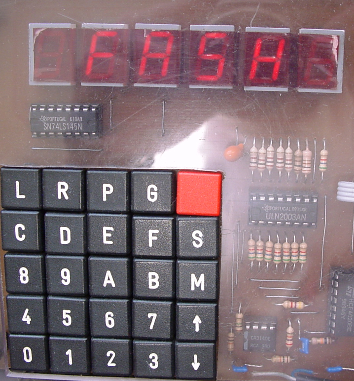
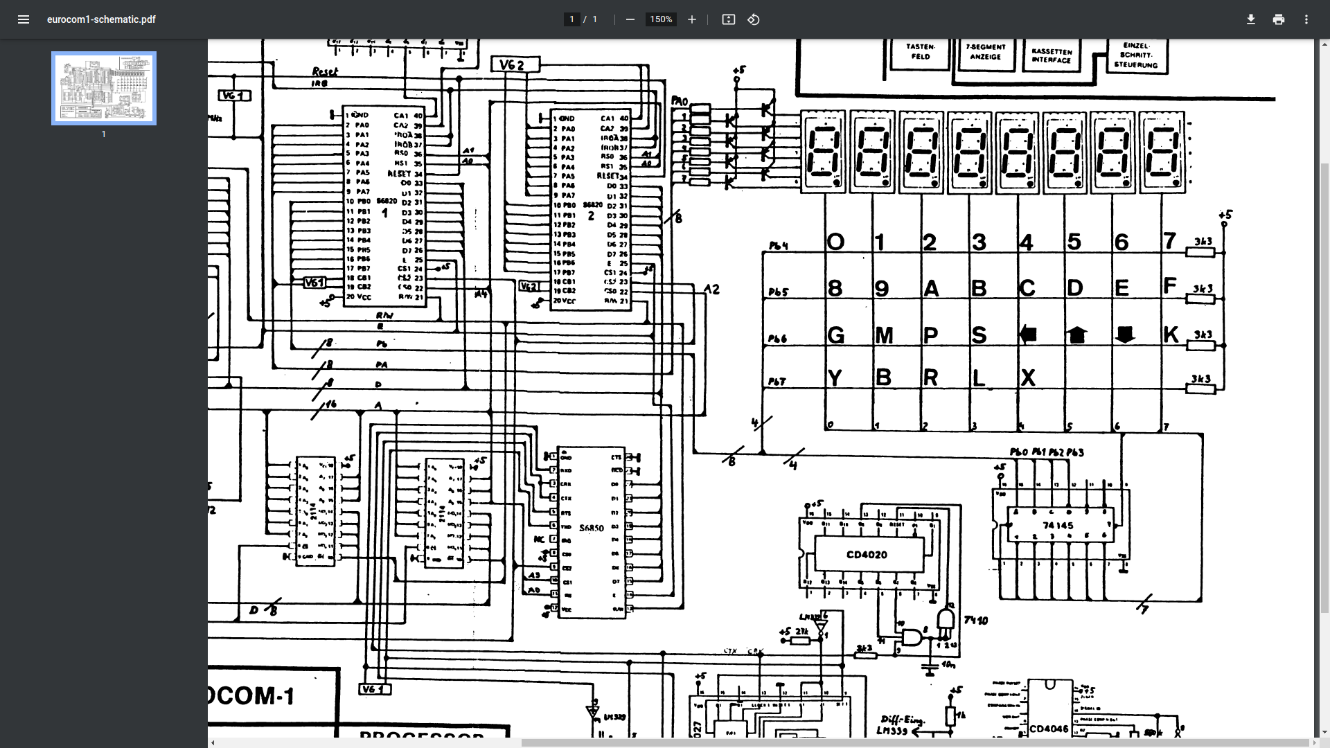
Eltec 6800
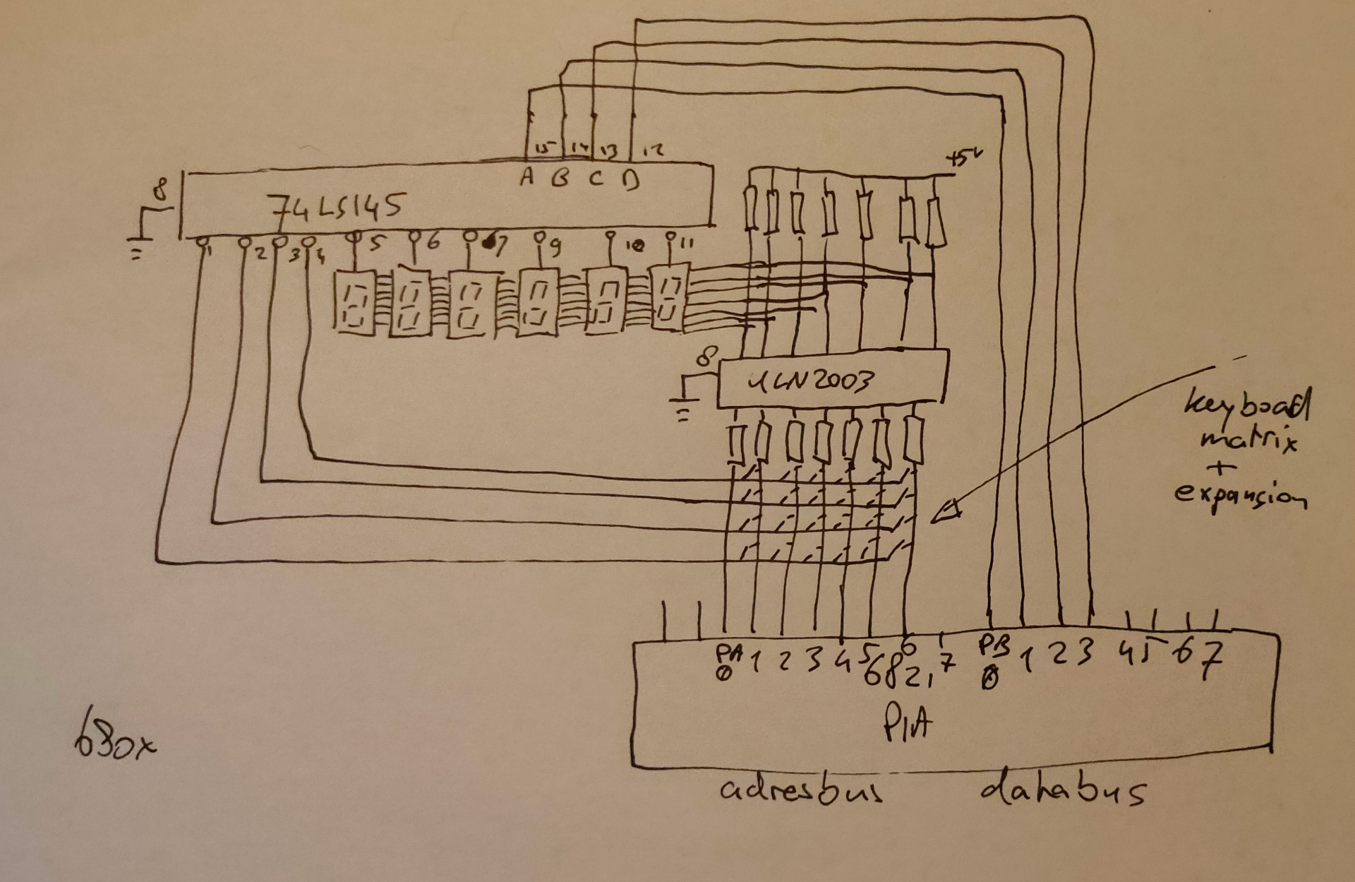
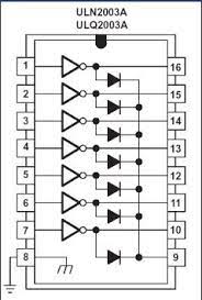
My version using darlington arrays (ULN2003)
When looking at the 8085 version you see transistors being a ULN2003 is a chip with those transistors/amplification enclosed. It doesn´t draw much current from the bus, and diodes protect the way the current flows.
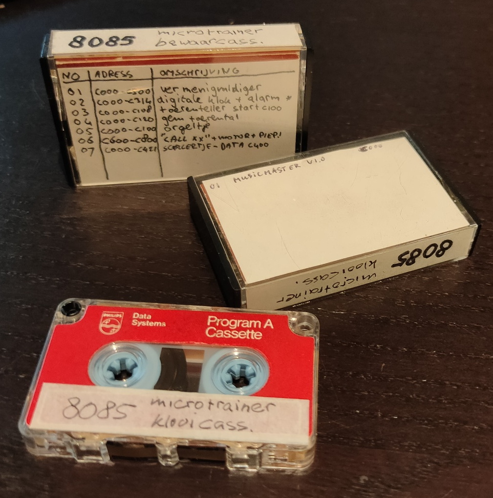
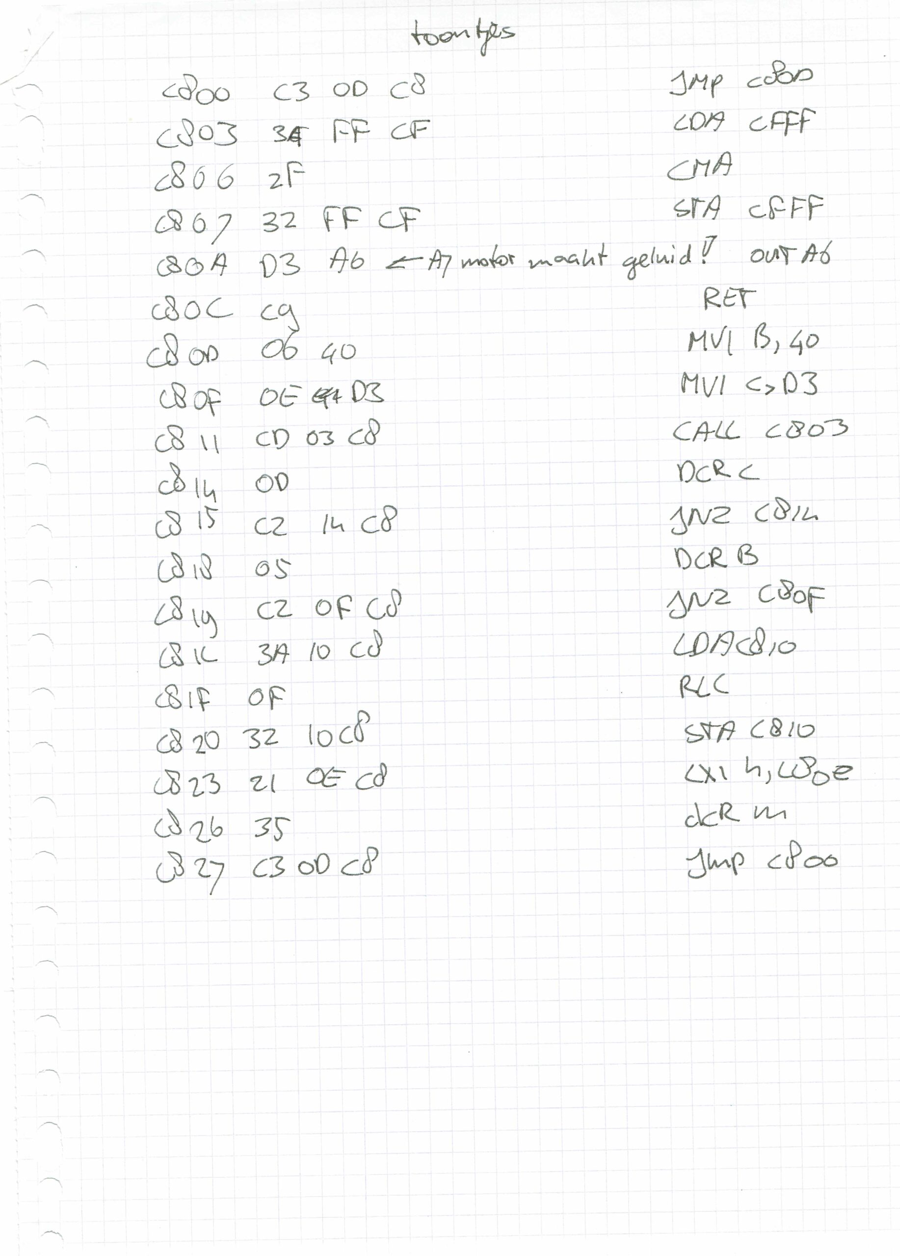
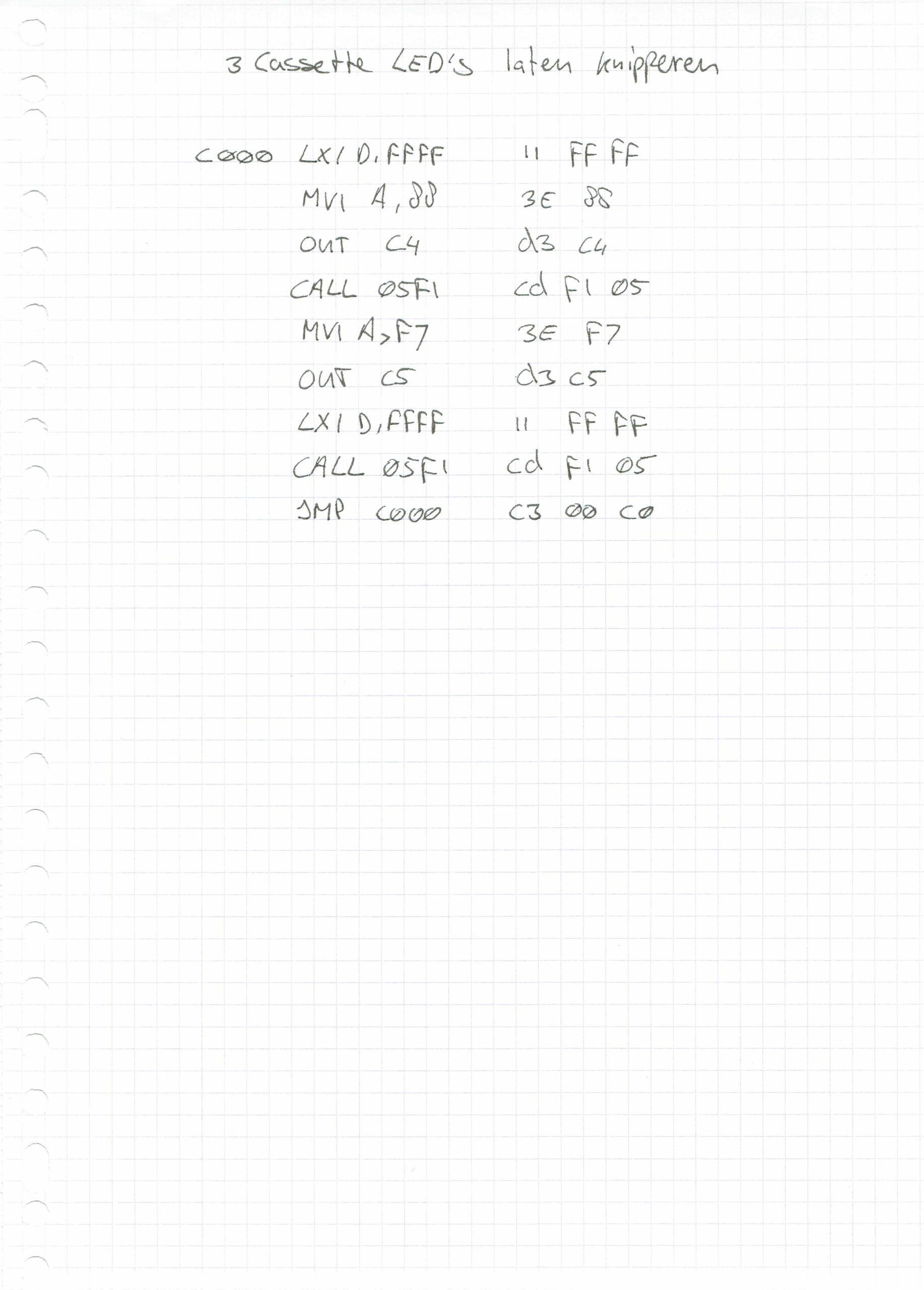
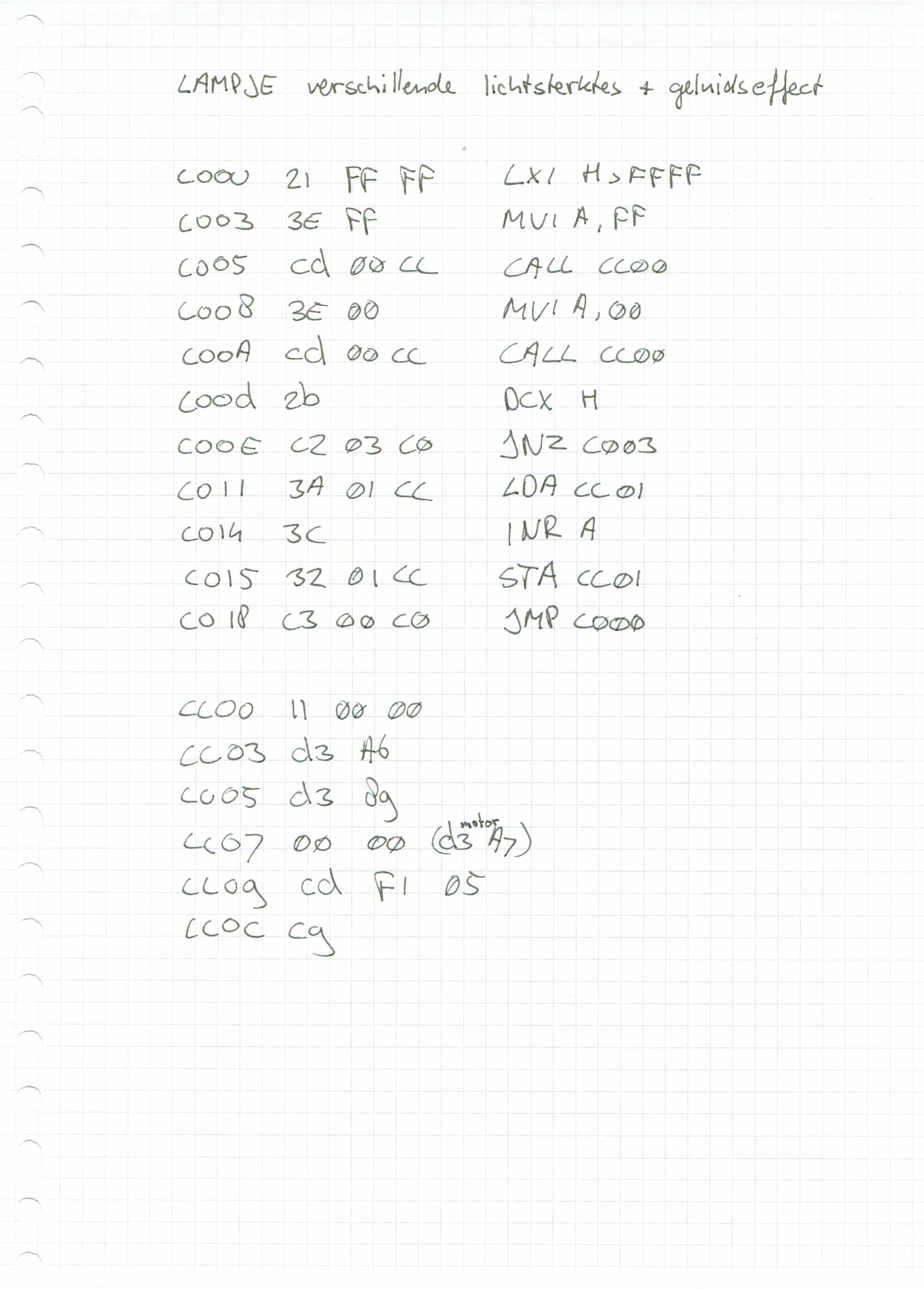
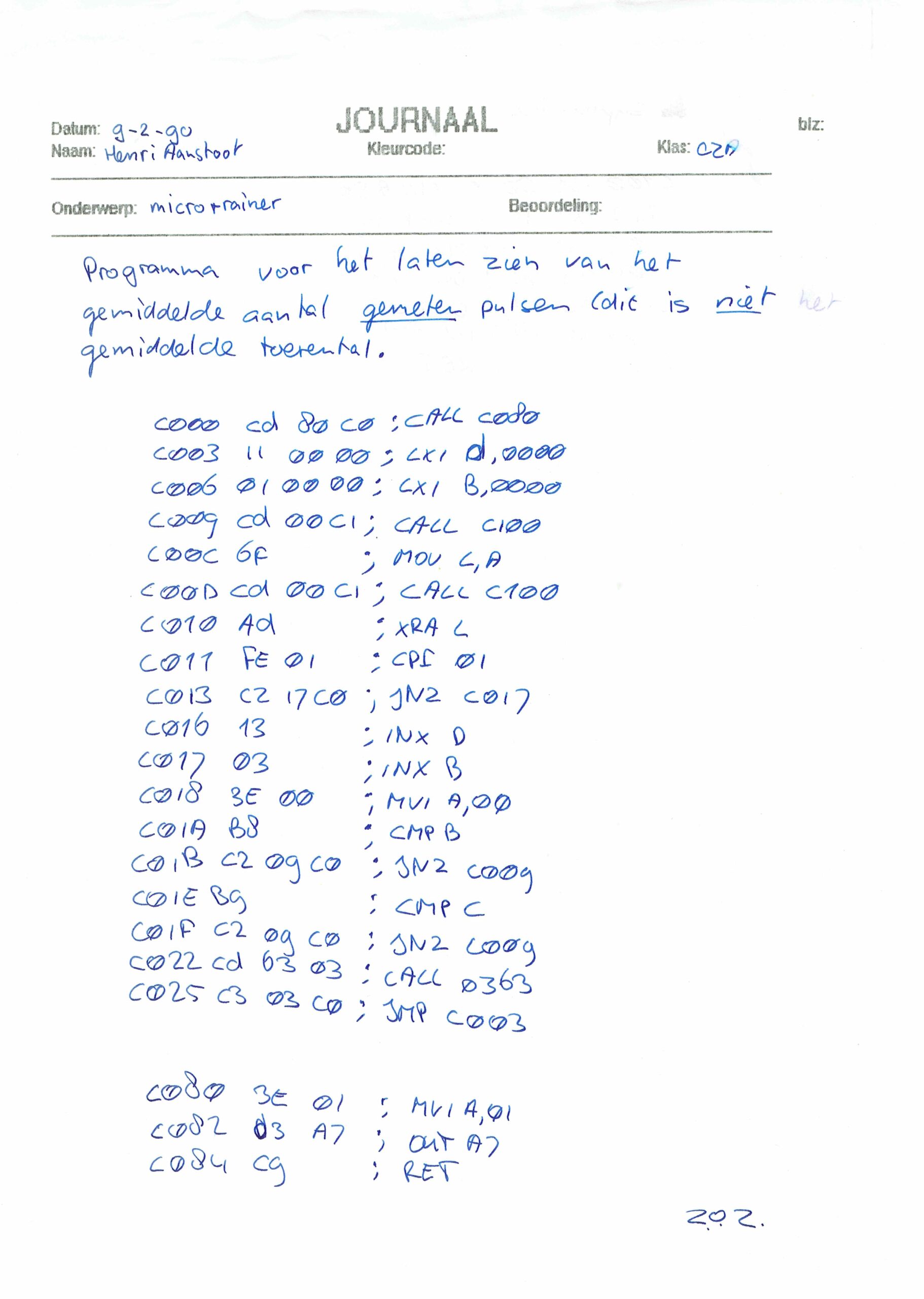
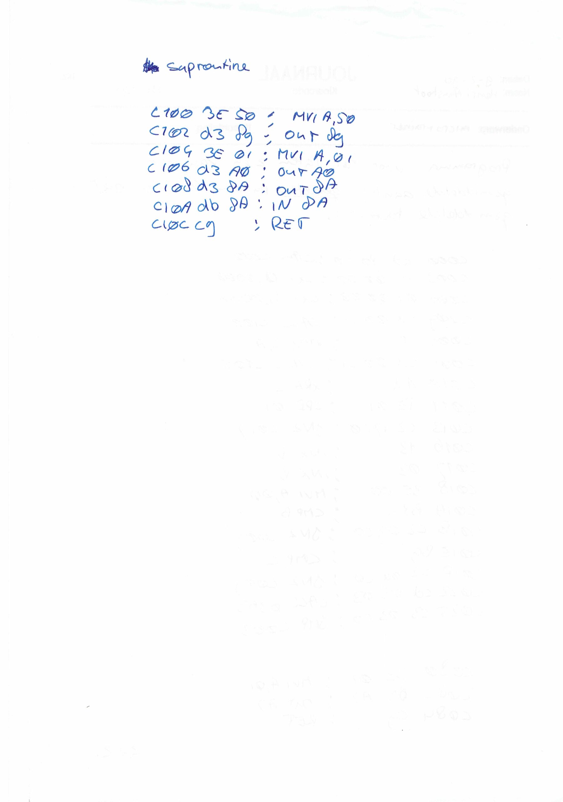
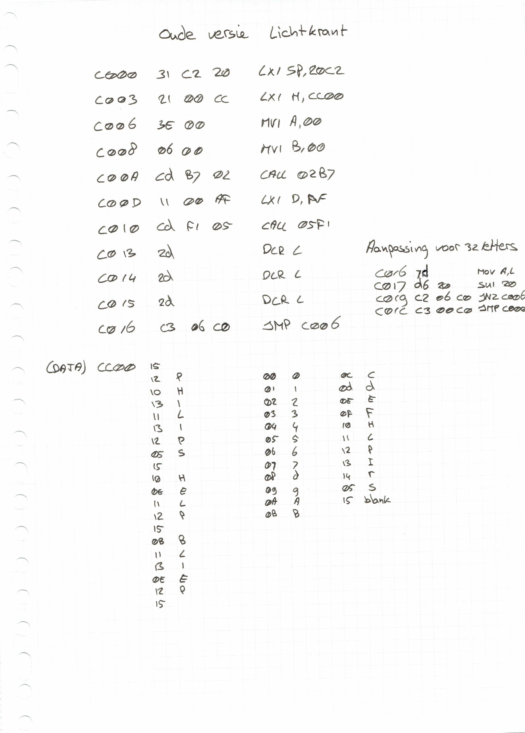
Found these old .. old mini-cassettes .. wish i could read these now. The sdk units we had, had tapedrives and few other hardware devices you could play with. Like a motor you could control, which had a disc with slots in it on top. These slots could be read and counted with a sensor to determine the speed.
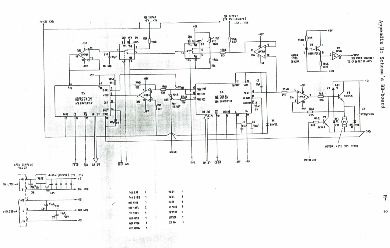
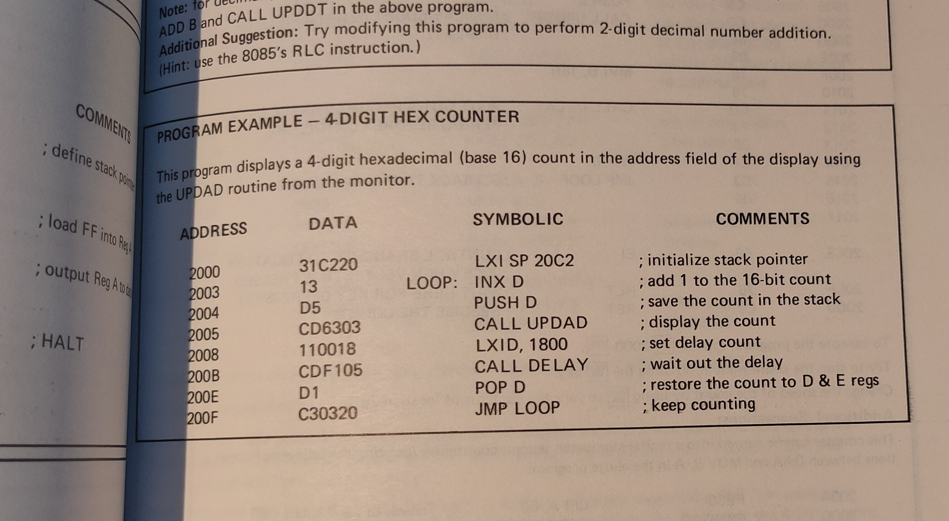
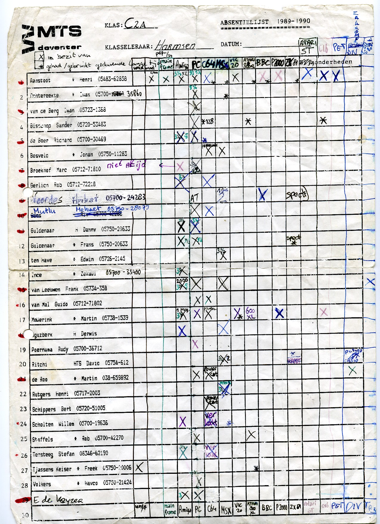
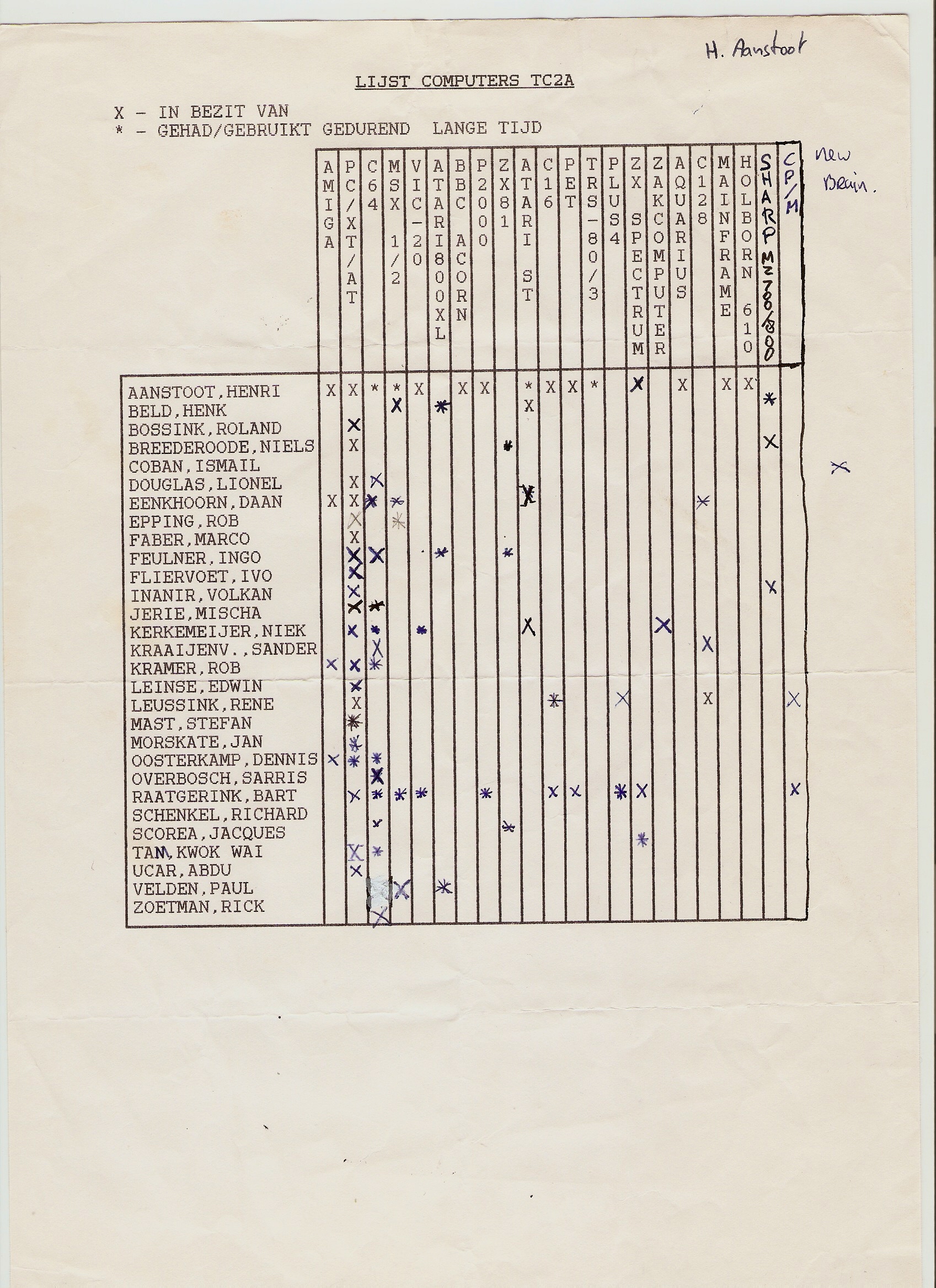
Also this scanned pages, from school i found. There should also be a little notbook with programs and notes ..
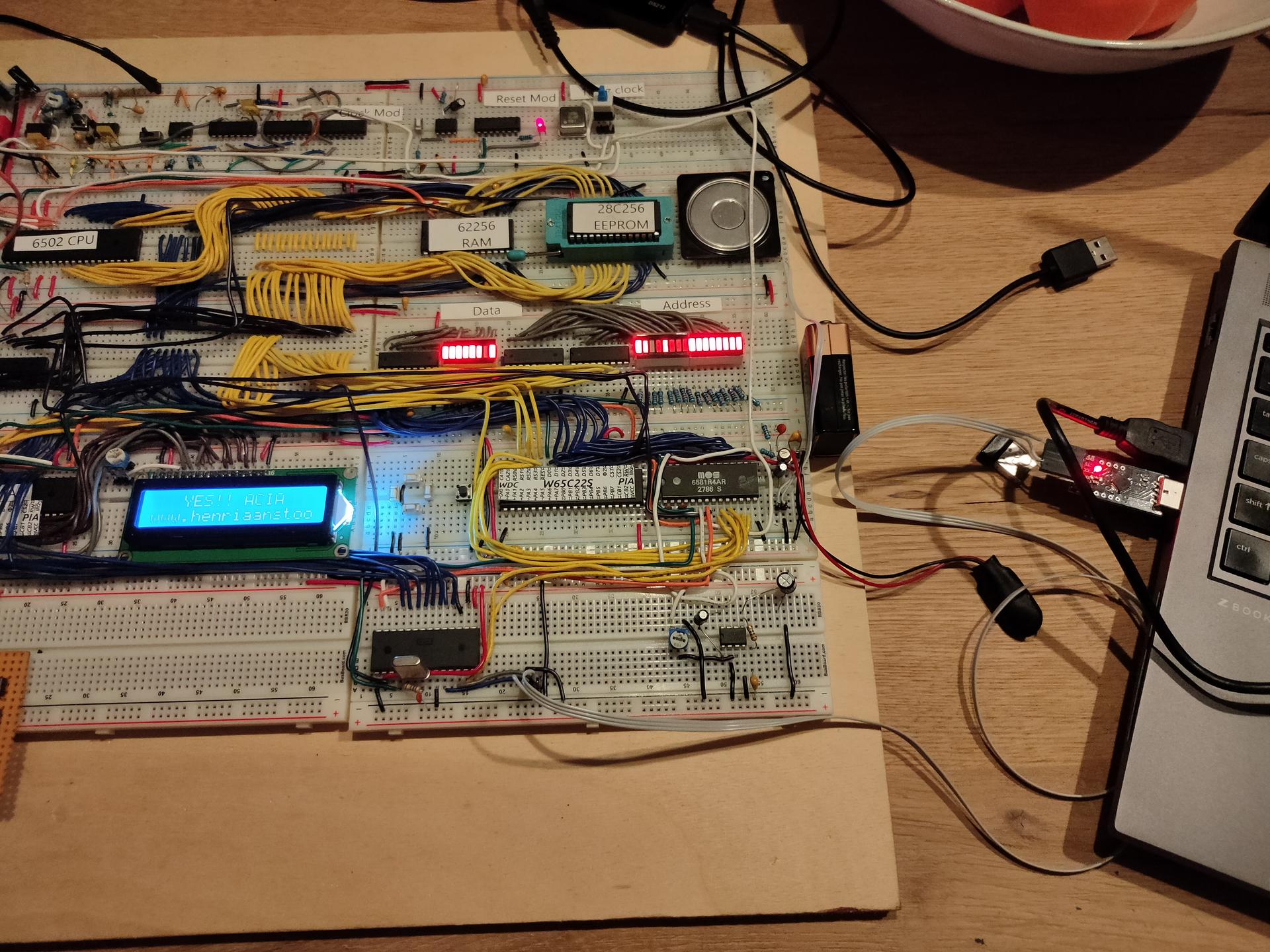
New address decoder in place! Connected RAM/ROM/SID/VIA1/VIA2 and ACIA
ROM
8000-FFFF
SID
7000-700F (sound)
VIA1
6000-60xx (Hex key matrix)
ACIA
6800-68xx (serial)
VIA2
5000-50xx (led test at the moment)
RAM
0000-3FFF
To plan: Bigger maxtrix keyboard and other displays
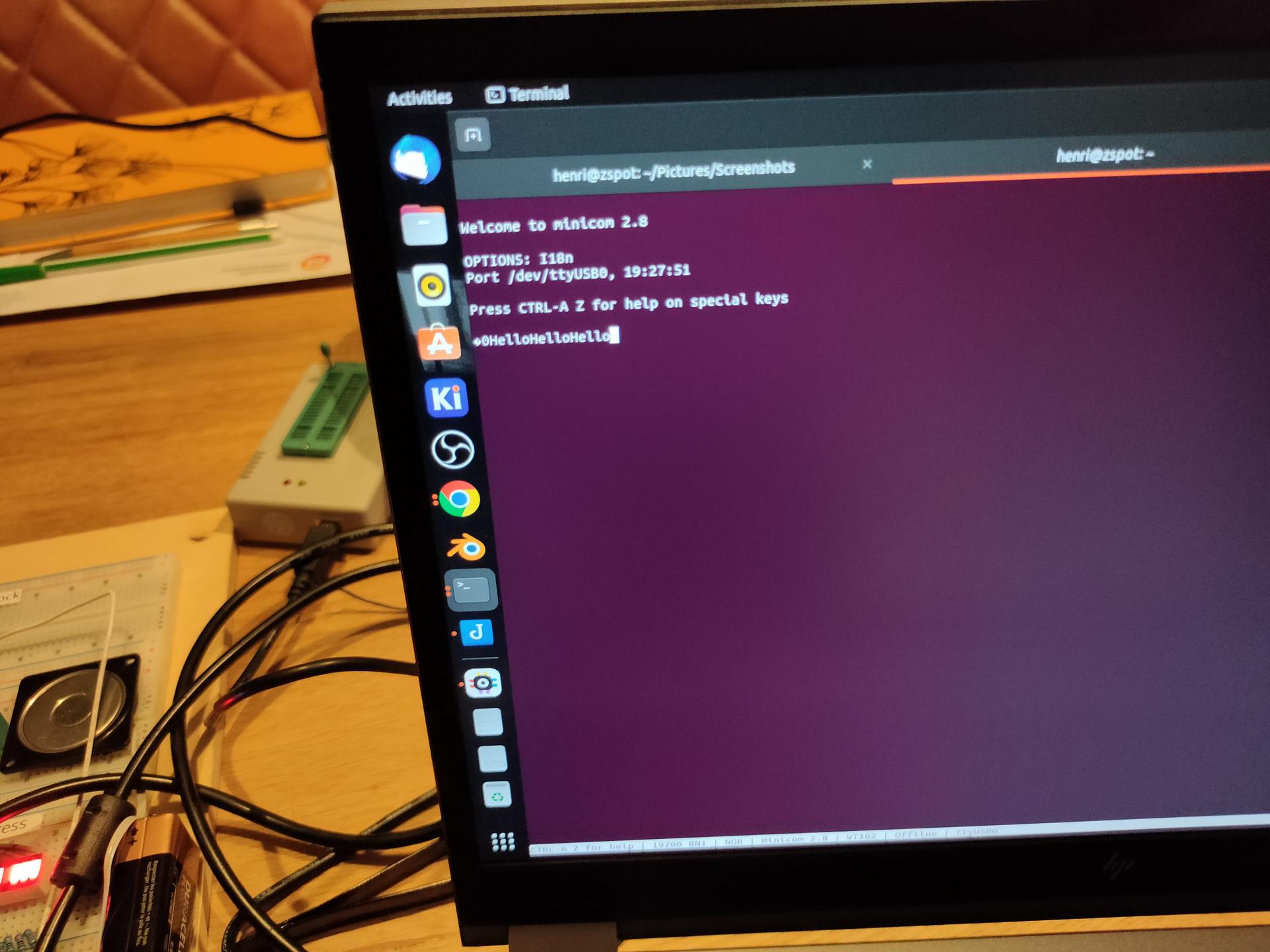
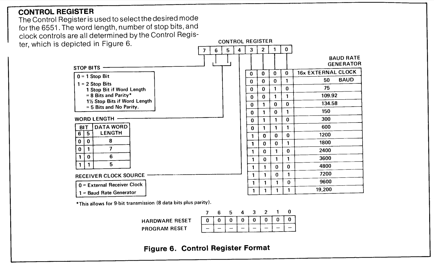
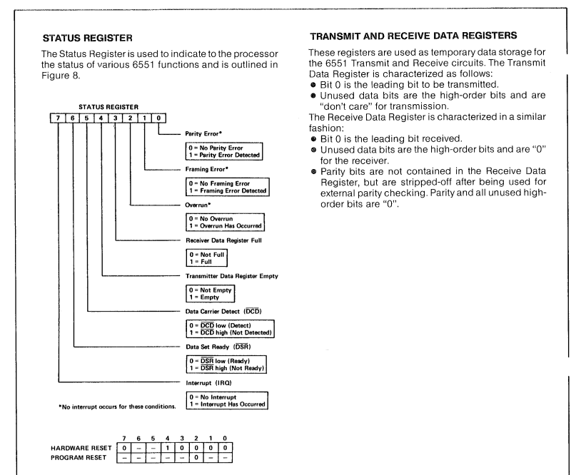
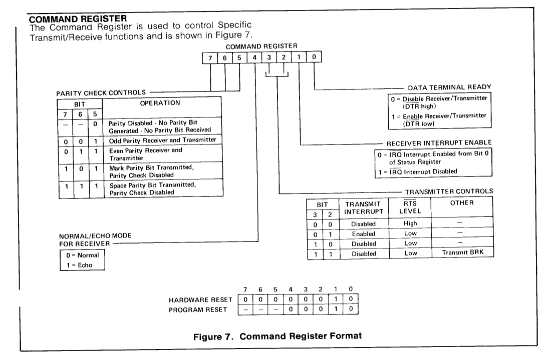
ACIA 6551
Got a serial connection working between the 6502 and my linux machine!
3 line serial – no hardware handshake
At the moment when a reset occurs , hello is being printed. Text typed in the minicom terminal, is echo-ed back and displayed on the LCD display.
Things learned: Do not trust internet schematics blindly!
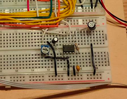
The crystal used for the ACIA (pin 6/7 1.8432Mhz needs a 1M ohm resistor parallel over the crystal, and a 30nF capacitor from pin 7 to GND
When using a terminal emulator, and using 3 wires. Disable hardware handshake.
Keyboard rewired.
What didn´t work as planned:
New amplifier schematic for the SID. There is too much noise.
Amplifier with a LM628
Bought a dual power supply (5V and 12V). But this one has a lot of signal noise on the SID part and even my battlestation speakers!
LED test 2nd via
PORTB = $5000 ; VIA PORTB
PORTA = $5001 ; VIA PORTA
DDRB = $5002  ; Data direction register
DDRA = $5003  ; Data direction register

LED  = %10000000

	.org $8000

reset:

	lda #%11100000 ; Set top 3 pins on port A to output
	sta DDRA

	lda LED
	sta PORTA

loop:		; done loop until doomsday
	jmp loop

irq:
nmi:
	.org $fffa
	.word nmi
	.word reset
	.word irq
ACIA part
ACIA_RX = $6800
ACIA_TX = $6800
ACIA_STATUS = $6801
ACIA_COMMAND = $6802
ACIA_CONTROL = $6803

    lda #$00
    sta ACIA_STATUS
    lda #$0b
    sta ACIA_COMMAND
    lda #$1f
    sta ACIA_CONTROL
I was using zevv’s bucklespring way back since he was beta testing. https://github.com/zevv/bucklespring
Also cool-retro-term, i used whenever i felt nostalgic.
But both at the same time, how much fun is that!
(Both newly installed on my laptop, which i had to reinstall, because i f*cked it up beyond repair. installing openxr stuff. OpenXR is an open, royalty-free standard for access to virtual reality and augmented reality platforms and devices. )
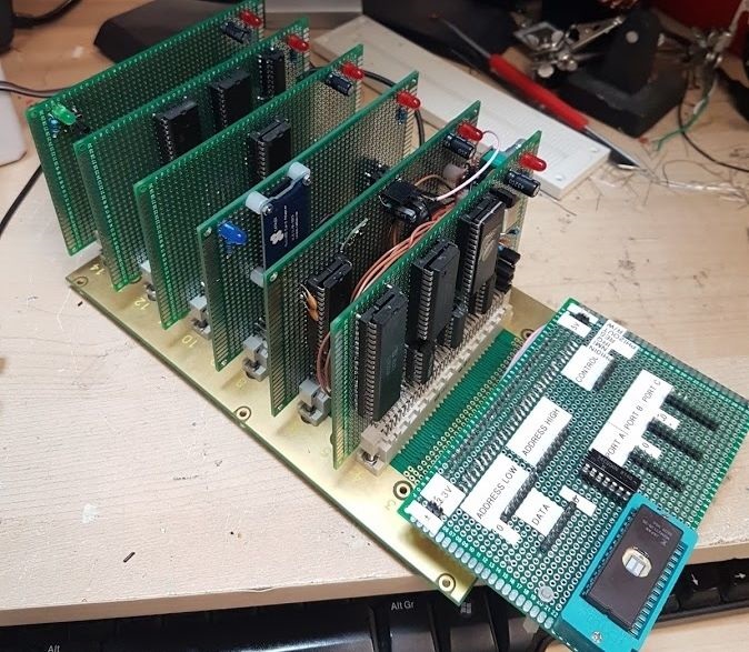
I found some stuff while sorting out some old computer stuff. Way back, when my Amiga was my main computer, i wanted to make my own version. A modular one.
So i started to segmentize the amiga, to put it on several exchangeable cards.
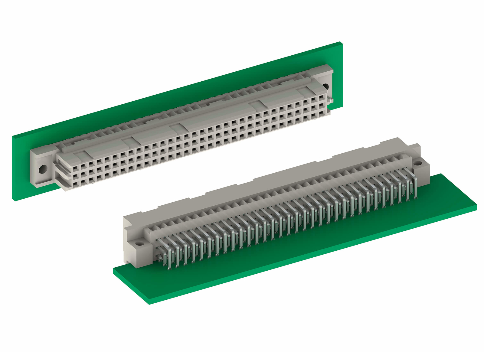
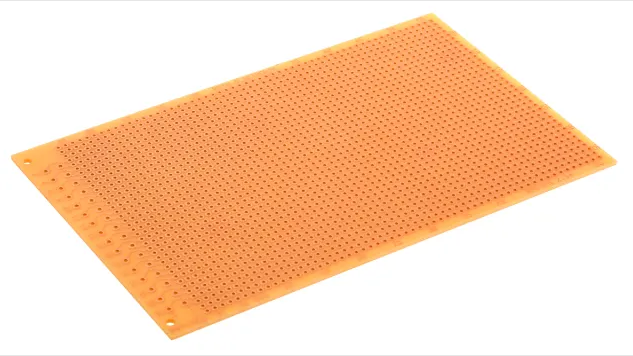
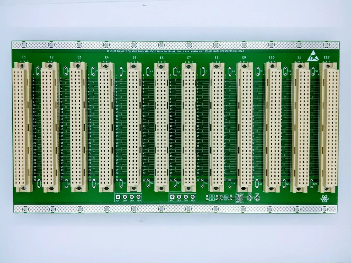
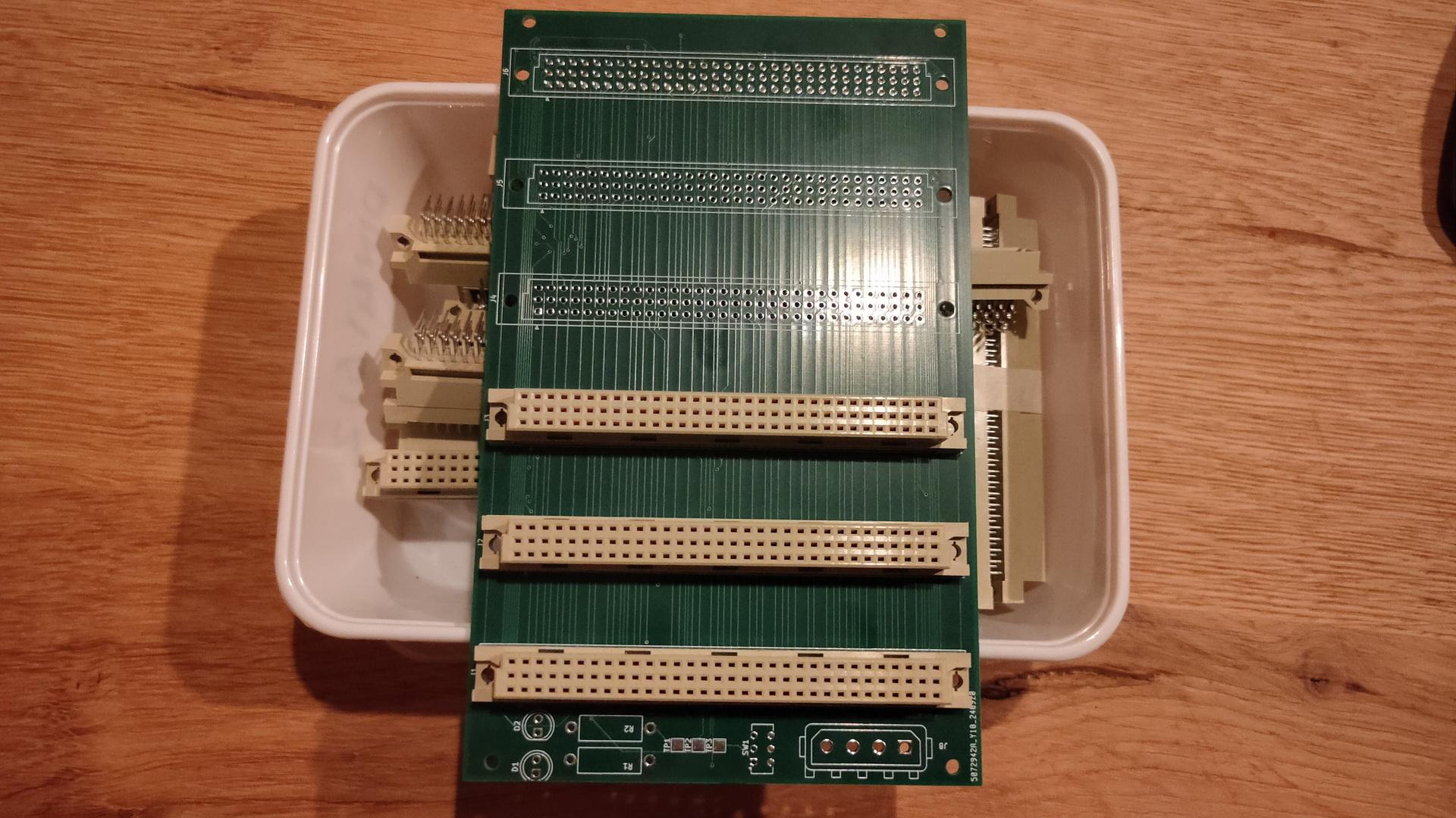
Eurocards are standardized prints 150mm x 100mm, mostly with a DIN41612 connector.
DIN41612
Eurocard example
When you make modules you can change/upgrade/test, you can have a very easy interchangeable system using a backplane like this
So i started planning those modules:
CPU – 68000 but upgradeable to 68030 or alike
Memory – With expansion
Sound
Video
More IO possibilities
Keyboard (see more at the bottom of this page)
I had a nice case which could hold a big backplane, custom powersupply. And a front panel containing drives, leds and knobs. (I know i have more info on this somewhere on my fileserver)
A nice example picture i found on danceswithferrets website
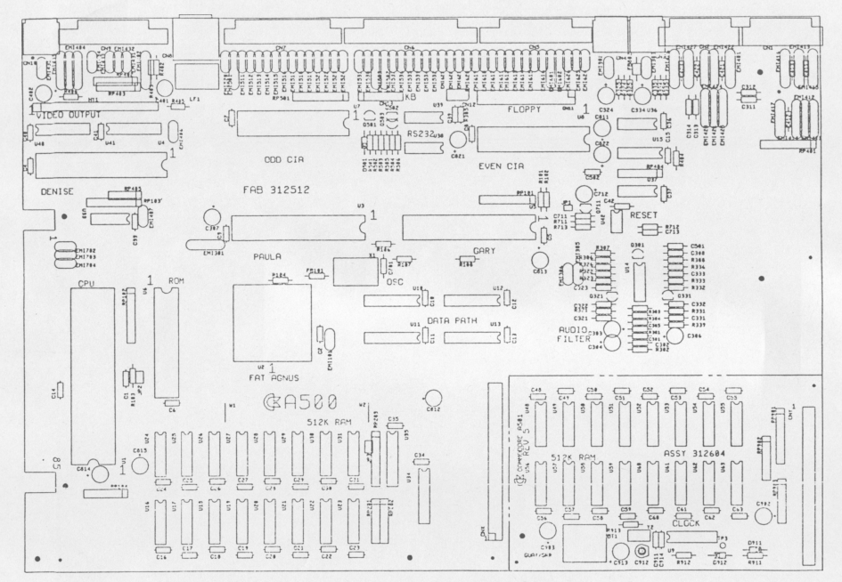
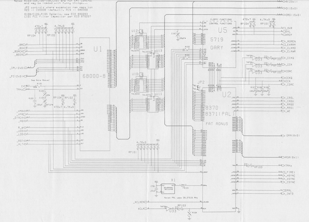
I never finished this project. I used Tech Manuals and print layouts to understand how things where done.
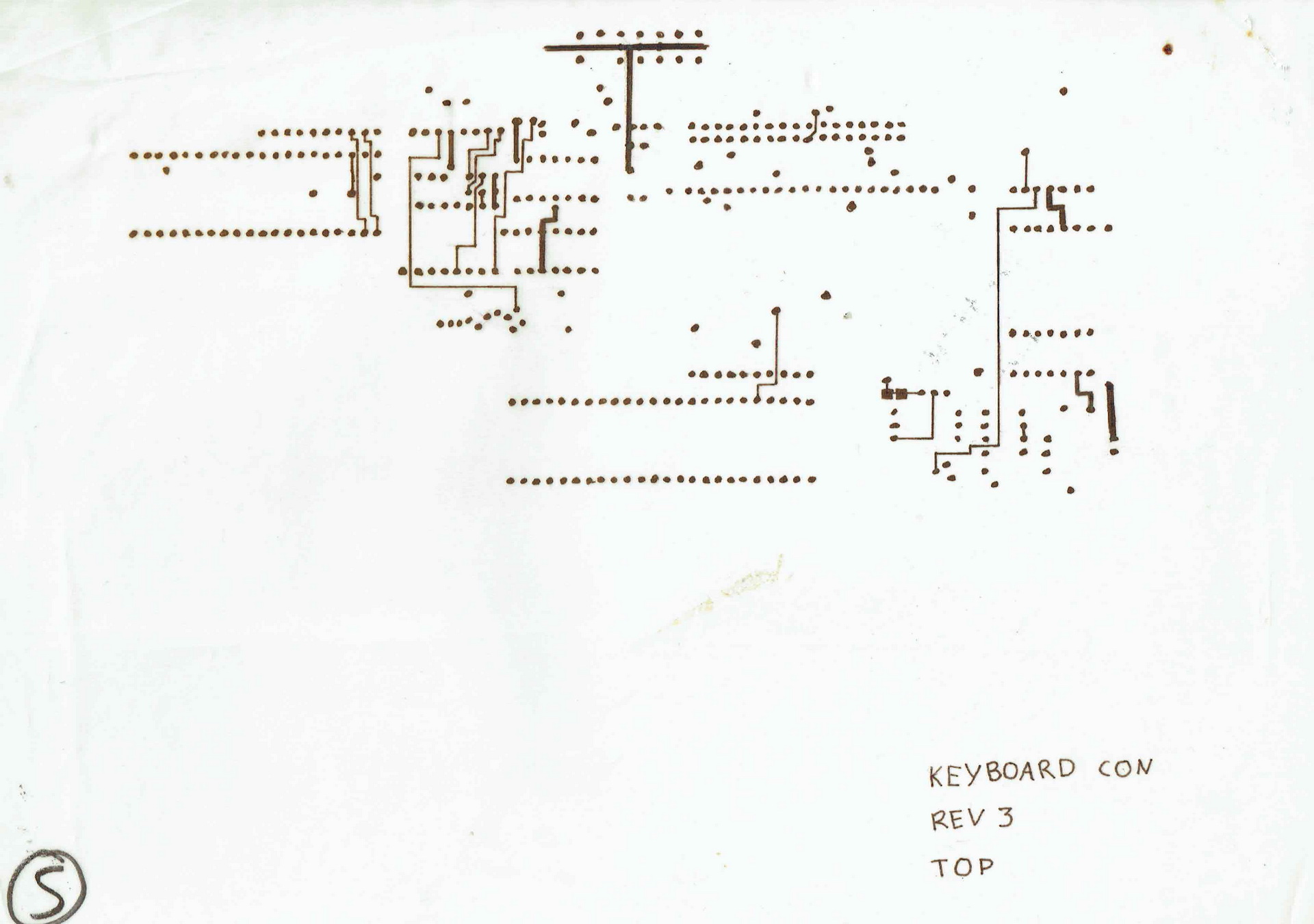
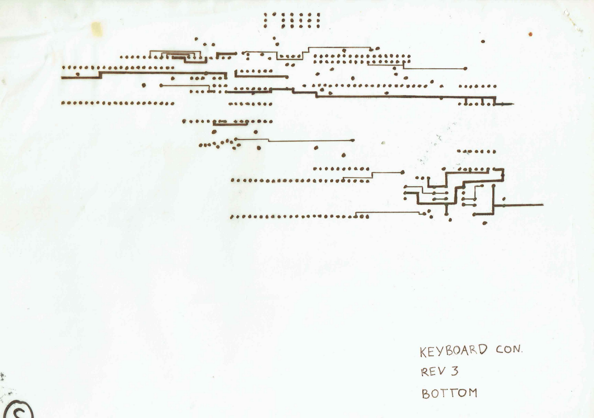
Part of schematic
I started to draw the modules like they where placed on the print on semi transparent (chalk)paper, the kind of paper that was used for electronic and mechanic diagrams.
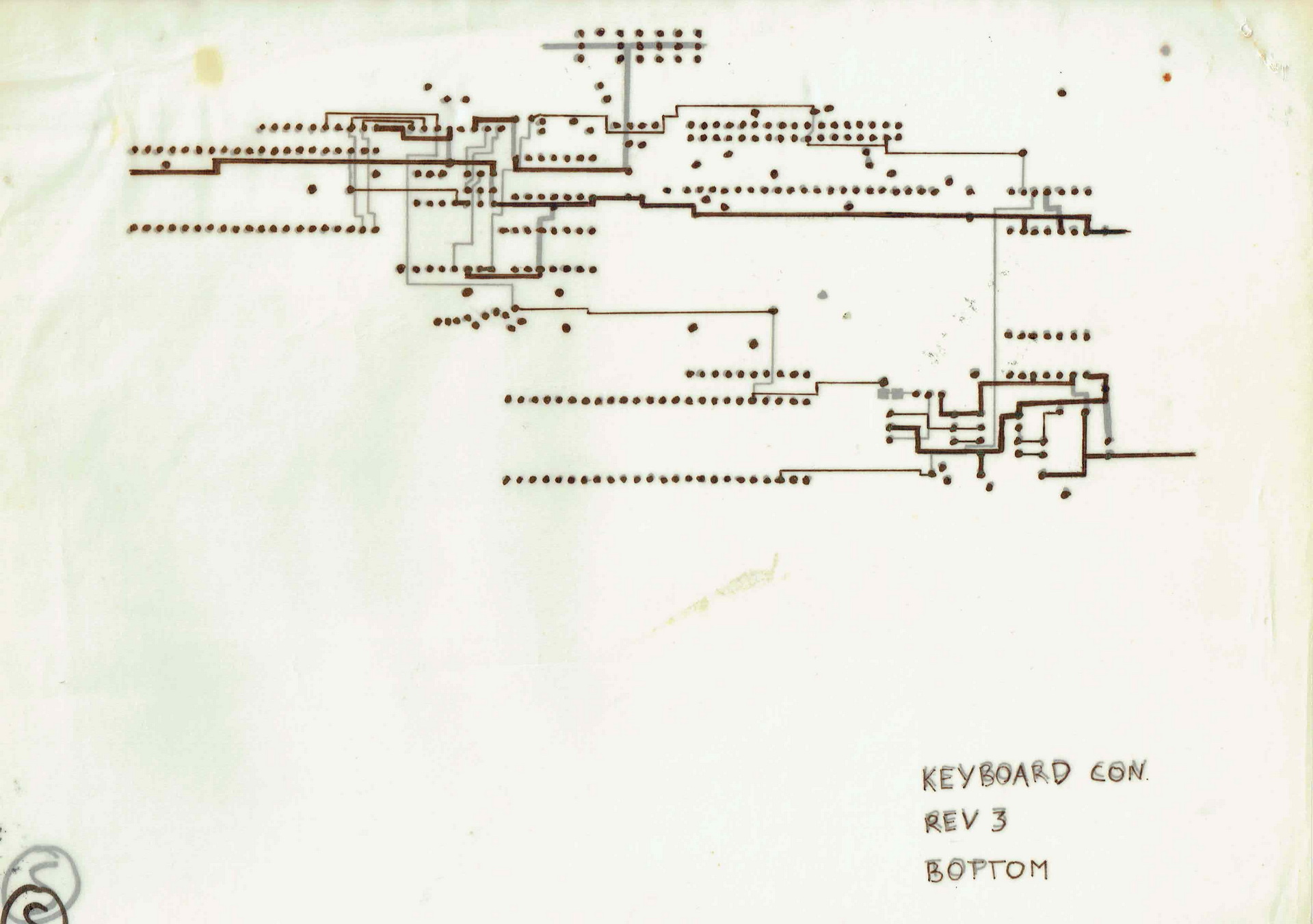
TOP Part of printBottom part of printBoth on top of eachother
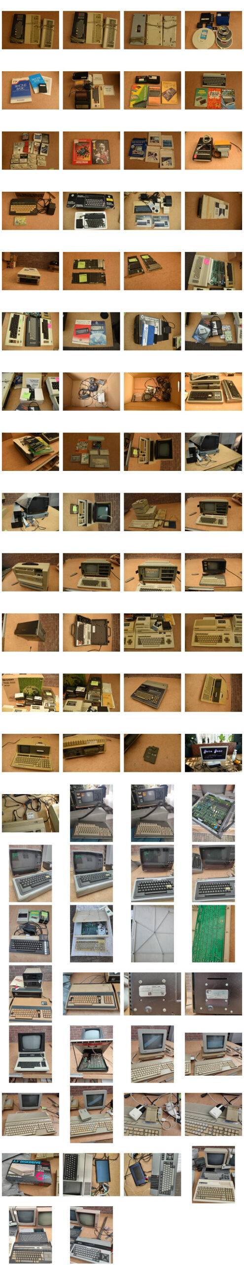
The last days i’ve been selling a lot of my old computers. They have been in my collection for many years, but now its time to part. Time for others to enjoy them.
(Instead of posting which ones are being sold and which i’ve still got on this page i’ll make another post)
I started collecting when i studied computer sciences. It’s a wonder my parents attic wasn’t collapsing. (They let me store many computers on their attic, let me run a mainframe in the house (previous post) and let me have computer-parties (pre-lan) in their home. (They even left, and gave me the space) .. 15+ teens with computers … there was a pingpong table in the livingroom (besides the other tables in the house ) For all computers.
Then i’ve got even more, when living on my own. (At some point about 140. )
A few years later i got rid of uninteresting computers (to my taste at that time) and incomplete ones. Then i filtered-out the non working.
Still leaving with a lot of computers, i kept these for many years.
Now i only want the ones i’ve worked with, or are special to me.
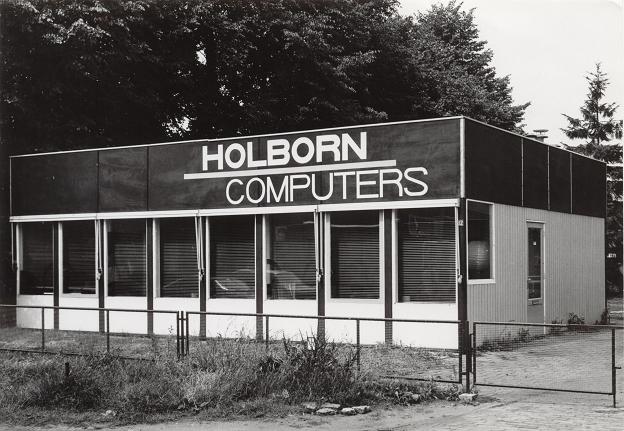
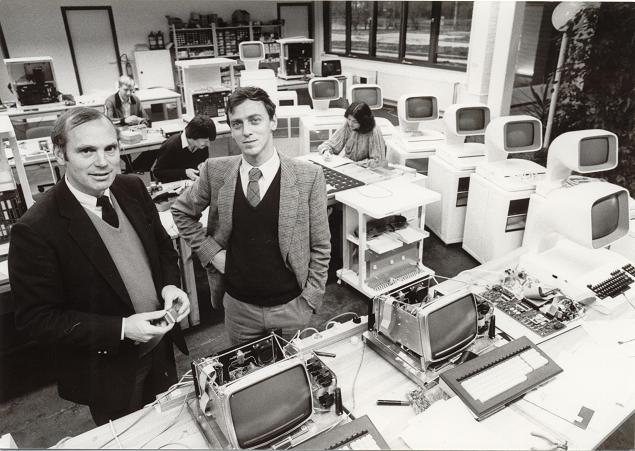
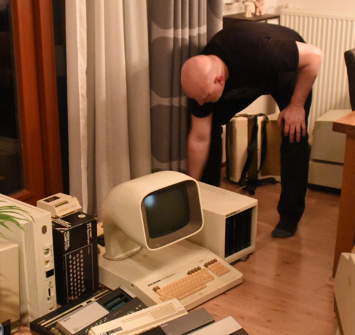
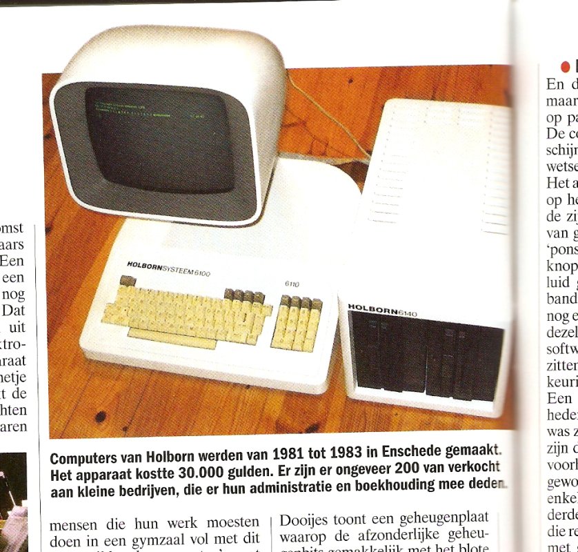
My first computer was a Commodore Vic-20. Friends had the popular C64. So i kept 2 of both. In Junior Technical School i’ve used the BBC Acorn a lot (Funny story below) My then friend Richard had a Atari ST, loads of fun we had with that machine, so i’m keeping a Atari 1040STf. Another friend used a Apple SE, so that one i also keep for now. I’ve been programming a lot on 80×86, the first dos PC’s, i’m still looking for a old machine (Laser XT) which i used way back then. But for now i’ve got a Sinclair PC200. I’ll keep a old Commodore PET 2001, because its cute. Besides having a cute PET, i’ve got a Holborn System. Made in Holland (Enschede), there are only a few left according to some sites: only 200 made! (Holborn means Holland Born) One of the inventors was from Holten, my birthplace. (Polak)
Putting the system together in 2018
At school we kept a list of everyone’s collection.
Soo .. the story about the BBC Acorn.
When i was at school outside study hours, i went to the computer lab. This was one classroom with about 16 BBC Acorns and a master (teacher station). When they saw how enthusiastic i was, i got the key to the classroom. I even got access to the master system. And after a little hacking i’ve gained access to the teachers files. There was a simple network system, i think it was called Econet. The teachers system was the only one with a disk station.
I liked the ‘highres’ line graphics you could make on the machines. (640×256) So i’ve wrote a lot of programs using this mode. I even wrote a program which drew a 3D robotarm on screen using wireframe graphics. At that time my mathematics scores where .. bad. Wasn’t interested i think. But drawing 3D robotic arms are not possible using mathematics, like using sinus, triangulary etcetera. So when my mathematics teacher saw my program, he didn’t believe me. So .. fooling around in the computer lab, i missed start of classes. And later on .. worse .. i almost was not allowed to do my final exams. I was late several times (and one of the first to leave, …. straight from and to the computer lab. )
I’ve got some programs printed on paper, i will use my leftover BBC Acorn (or a emulator) to capture some screen examples.
Sold stuff
UPDATE : Selling a lot, but i’ve bought some others between 2020-2023
SDK-85
Laser Xt/3
80386 DX
Also a “new” 1084 monitor (CRT for a Commodore 64) Now i have to look for a VGA Crt to get old vga-register manipulation programs working.
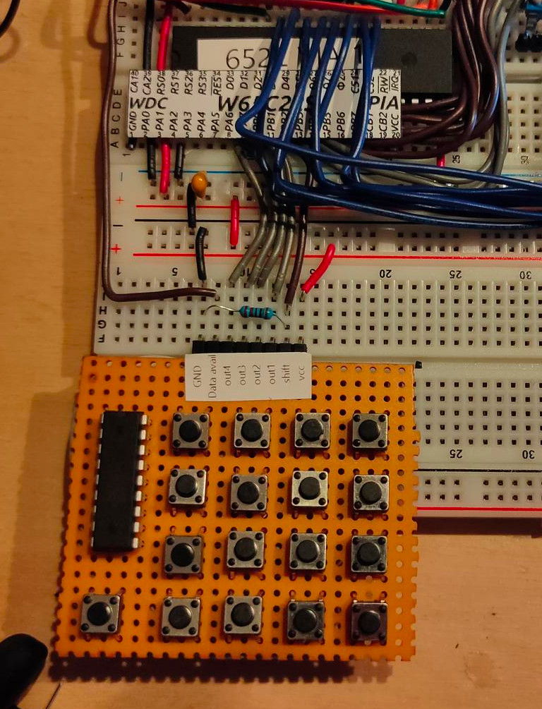
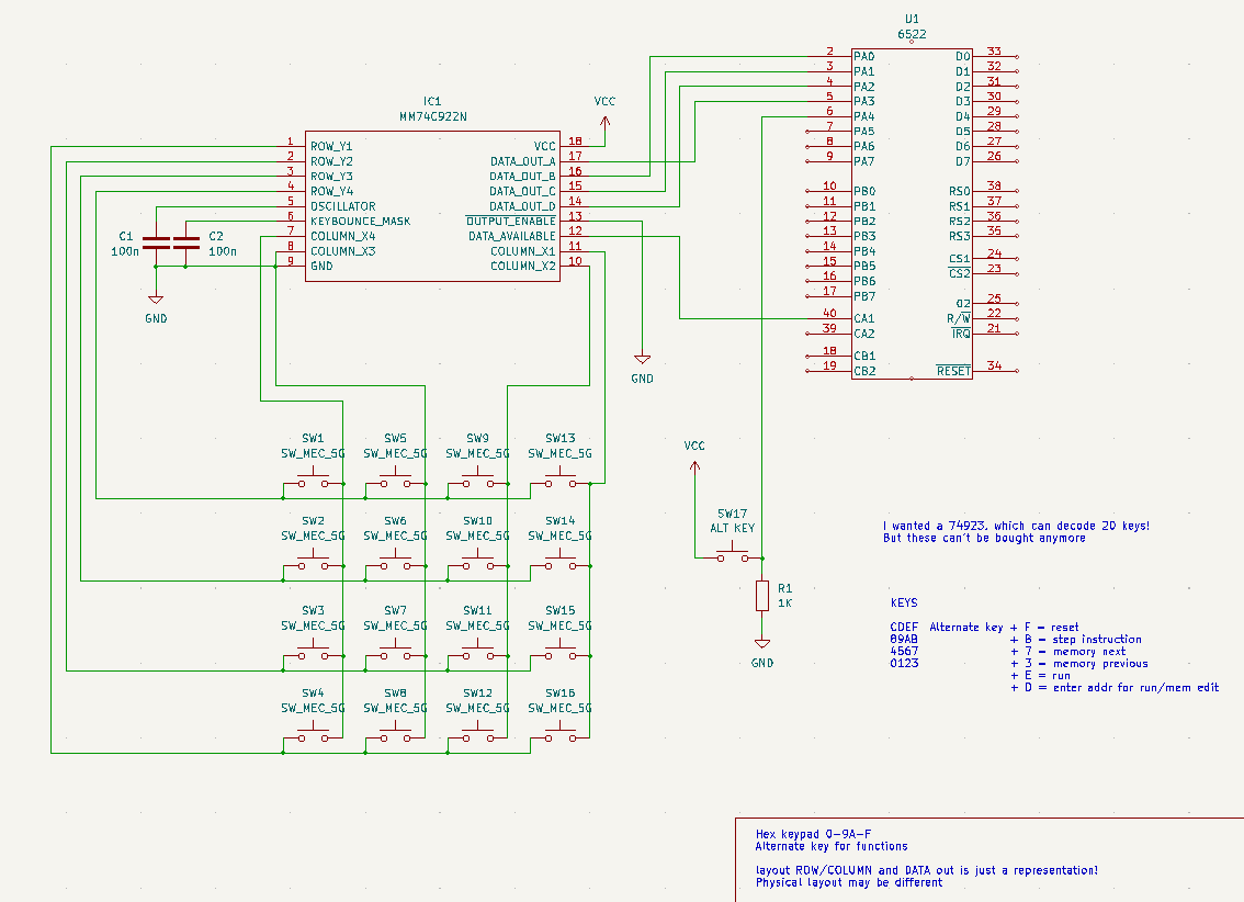
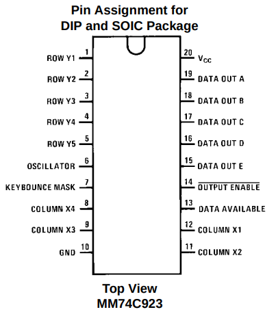
Above is my design for a hex keyboard to enter opcodes in hex using a simple monitor program. i used a 74ls922 which can decode a 4×4 matrix. I’d rather had a 74ls723 which can encode 20 keys.
Nowhere to be found. So i have to think of a new plan.
Now it is configured as follows:
C
D
E
F
8
9
A
B
4
5
6
7
0
1
2
3
When pressing the alternate key
addr (to implement)
run (1/2 implemented)
reset (to implement)
step instruction (to implement)
memory next
memory previous
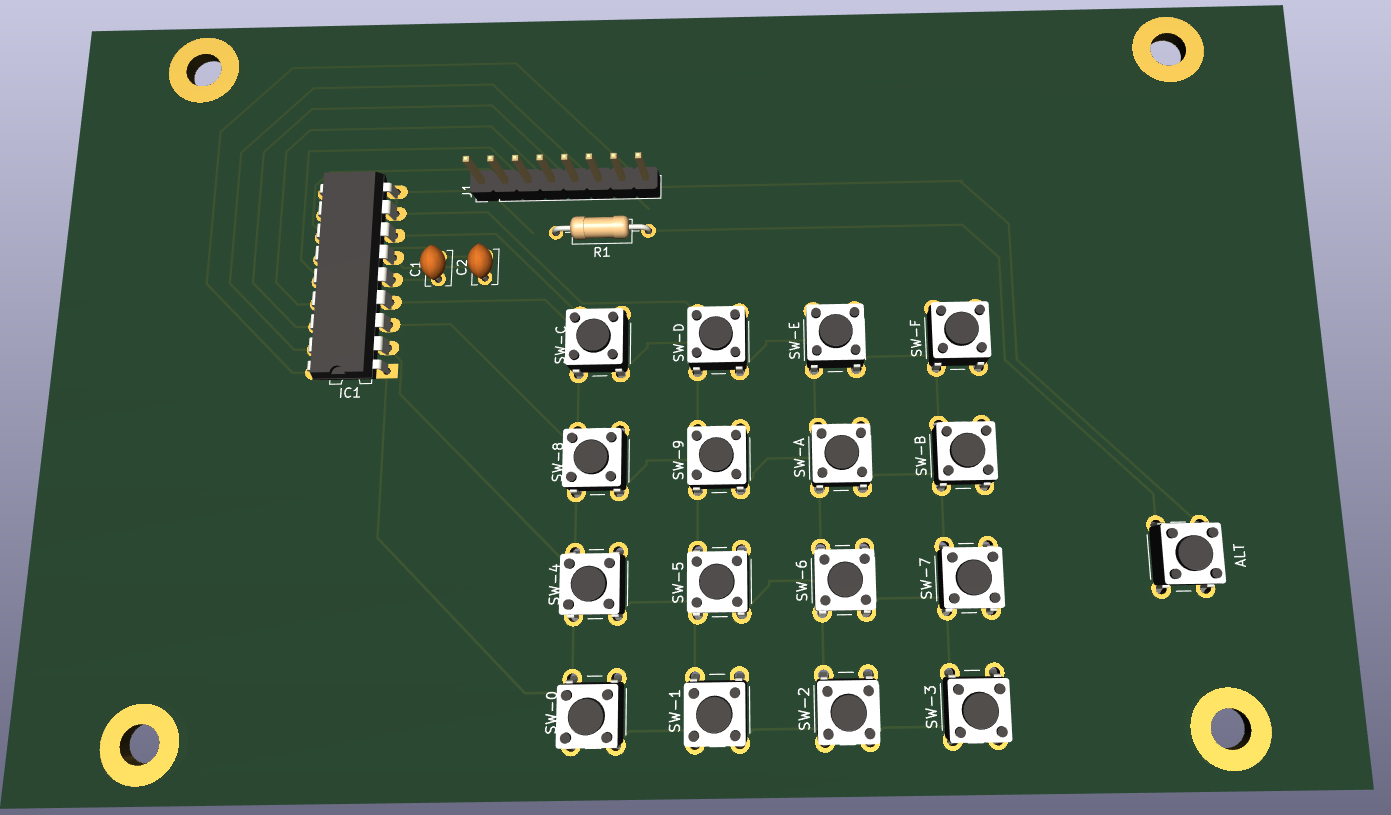
PCB design for matrix hexboard with place for notes
Meanwhile i’ve ordered new keys (the ones i’ve been using for my photomanager project and wnat to have a setup like this:
?
?
addr
run
reset
C
D
E
F
?
8
9
A
B
step
4
5
6
7
mem next
0
1
2
3
mem prev
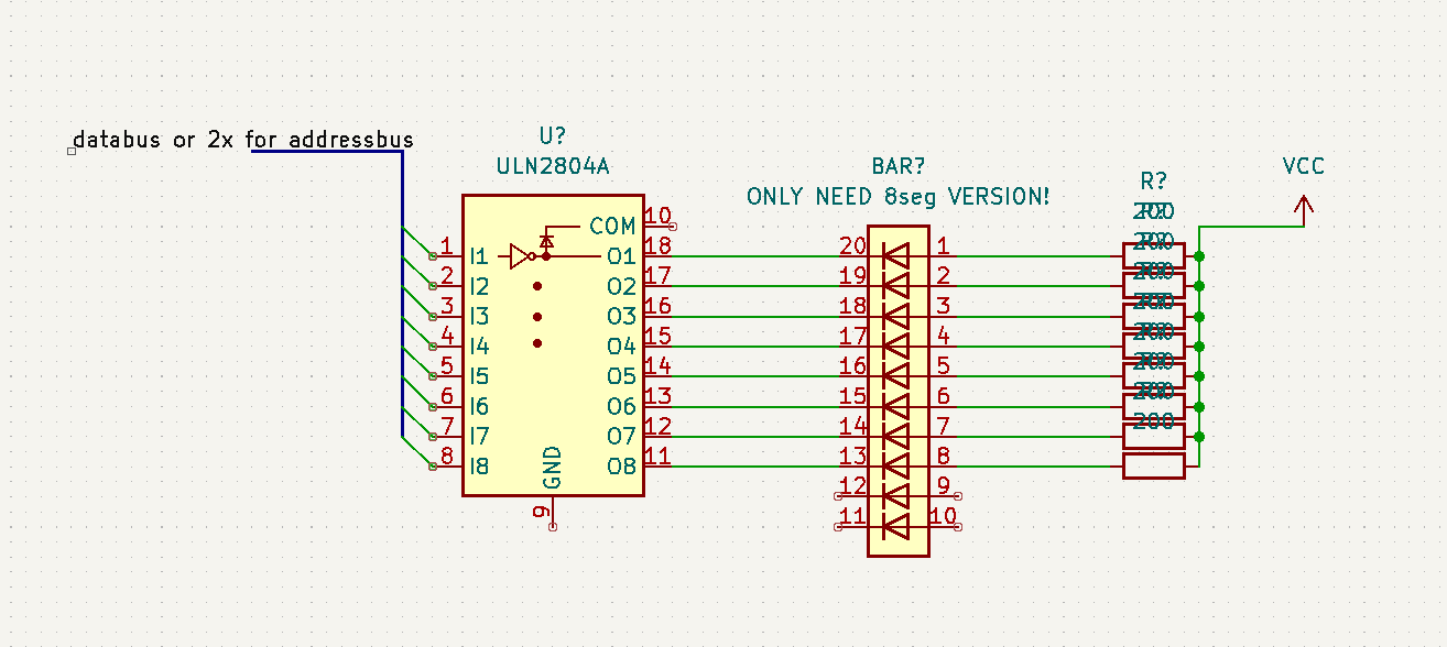
When you want to show the status of busses and alike, you can’t use a led and restistor directly on the bus, it will require too much current. So i’ve been using below schematic which uses a darlington array.
Now i can display databus, address bus and i’ve been using this for address decoding logic and hex keyboard.
I’ve implemented a second VIA chip, and ordered components to amplify the SID sound part
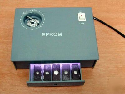
Flashing ROMs .. (eeproms). It used to be a pain in the *$$. Burning took a looong time. But clearing one with UV took .. 20 minutes or so. Using one of these:
Altered clock module
Changed button press
Dipswitches for more speed control (red .. upper left)
Changed Rom/Ram
Changed addressing
Added RAM
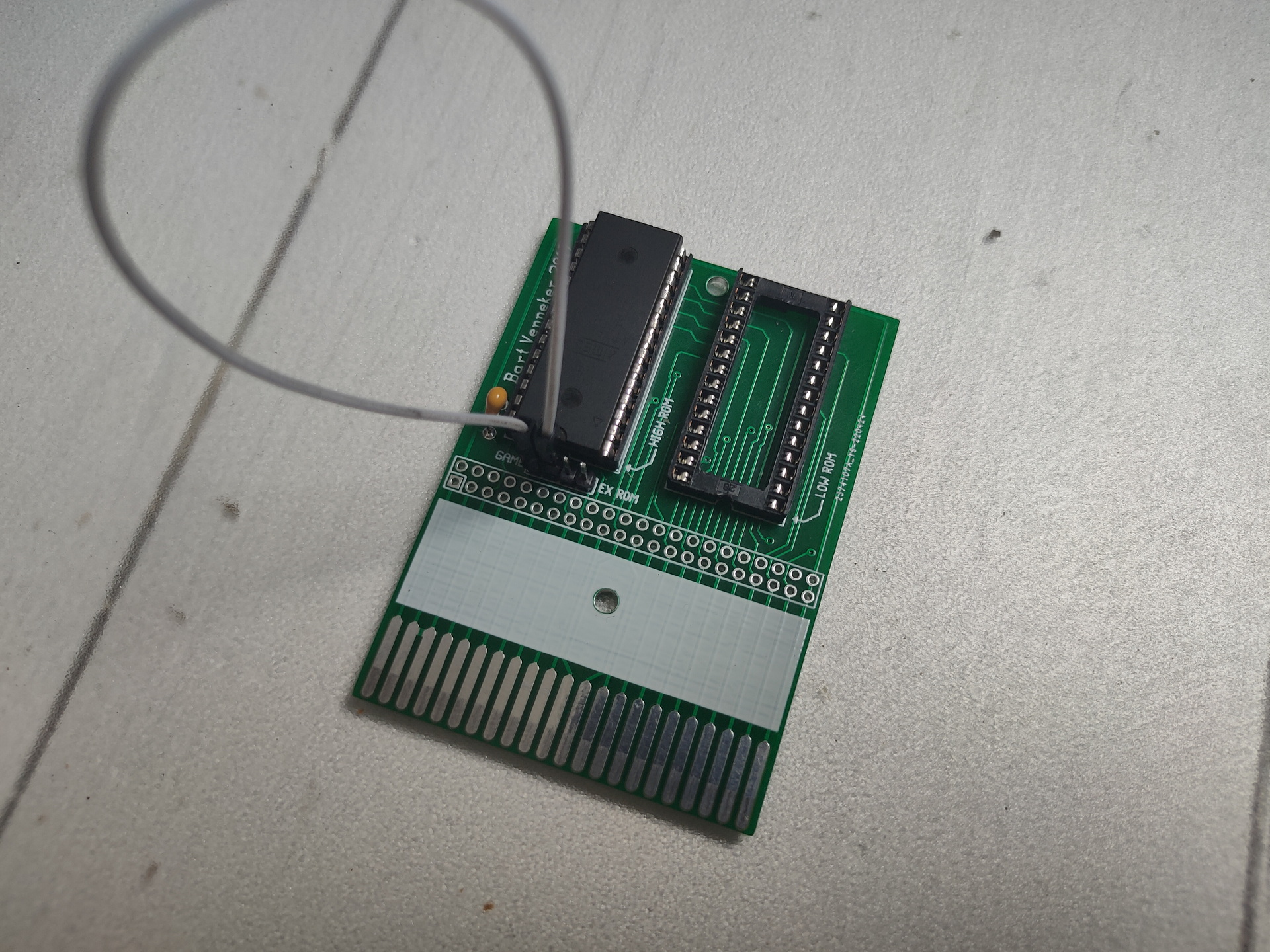
ZIF Socket for ROM
VIC 6522
Fixed clock
Added buttons for interrupt
Display
Display works now
To test: Create Address logic to access display without VIA Can work, but not at high speed clock. Stays behind VIA
To buy: st7920 lcd 128×64
Generic improvements
Rewired most parts, using color codes (Blue data, Yellow Address and so on)
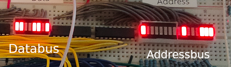
Added leds on data and address bus using ULN2803 darlington arrays
100nF Decoupling capacitors on the power rails
To do’s or ‘have to look into’s’
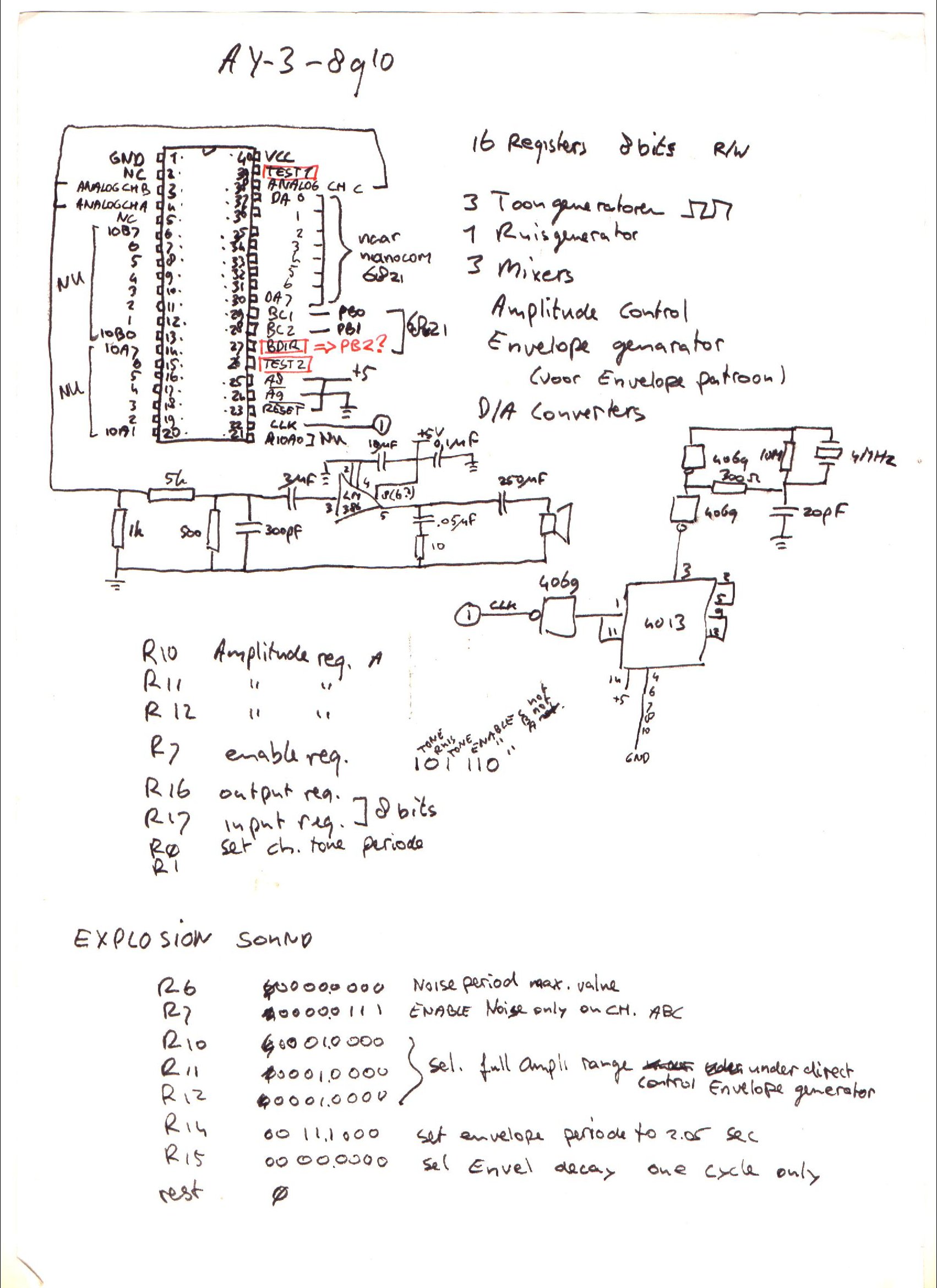
For sound i planned to use a General Instrument AY-3-8910, it is somewhere in my Lab, i know it is. I saved this chip and a SID for my Amiga addon soundcard. Where are my plans for the simple v1 setup? (FOUND IT)
I have to start writing rom functions for display usage. Like JSR $ff00 – Clear screen subroutine .. etc
I’m scraping information from websites, to get started on my clock controller. ATmega328 with ssd1306 display and rotary encoder/dip switches
Notes about the movie: Left side is Arduino IDE monitor reading Addressbus and Databus. (I’m going to try to rewrite this to realtime disassemble) Resetting system. Stepping CPU with manual clock pulses. Start vector being read at $FFFC/$FFFD. Program being run from $8000. Set clock on automatic ( ~ about 150 Hz ) Last opcodes you see a JMP loop 4C 2F 80, that is JMP $802F Display enlarged on video, was not visible on movie i took on mobile. (Wrong angle?)
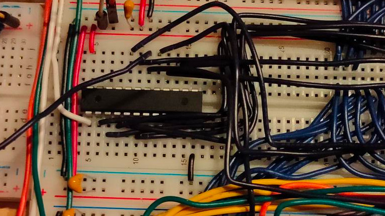
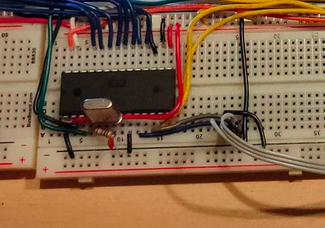
Breadboard overview
Clock module
Reset module + Crystal
CPU + nmi/int buttons
RAM and ROM
Address decode + Bus divide
Addres/Data bus leds
6522 VIA + Display
2nd via + Buttons
?
(sound board)
TIL: 6502 can run without ram only rom,expect when using JSR … which uses a program stack in RAM
TODO:
Make Clock module and 1Mhz Crystal switchable
NMI and INT debounce maken
Software buttons
Buy new darlingtons, for controlbus!
r/w, int, chip enables, etc
Labels on chips/breadboards
"If something is worth doing, it's worth overdoing."