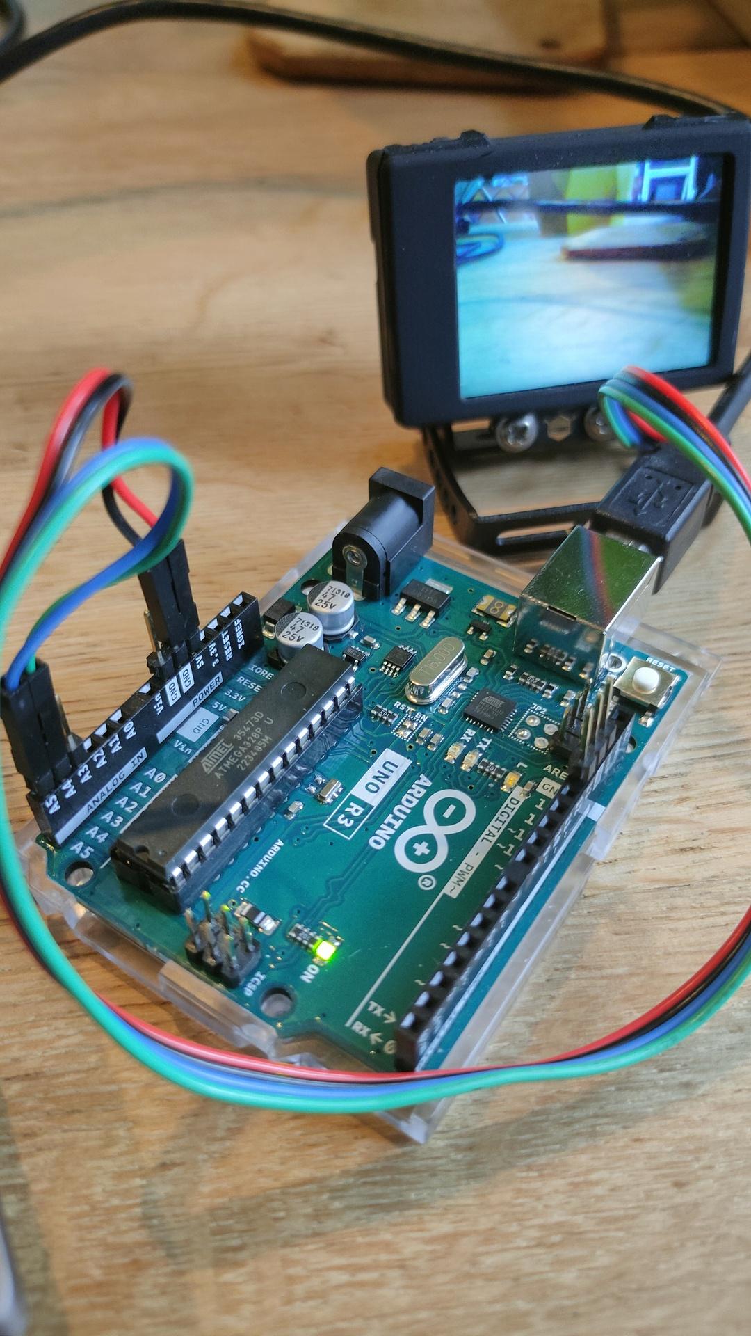
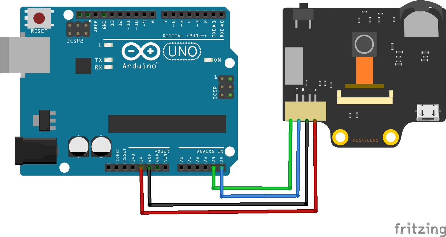
Arduino Uno with Husky Lens using I2C
The HuskyLens is an easy-to-use AI machine vision sensor. It is equipped with multiple functions such as:
- Face recognition
- Object tracking
- Object recognition
- Line trace
- Color recognition
- Tag recognition (QR code).
Via the UART / I2C port you can among others: boards connect:
- Arduino
- micro:bit
- Raspberry Pi
Steps to take: Press Face detection, when a cross in a square is displayed, press the button on your HuskyLens
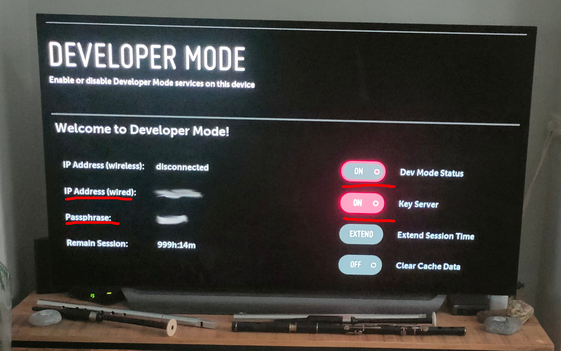
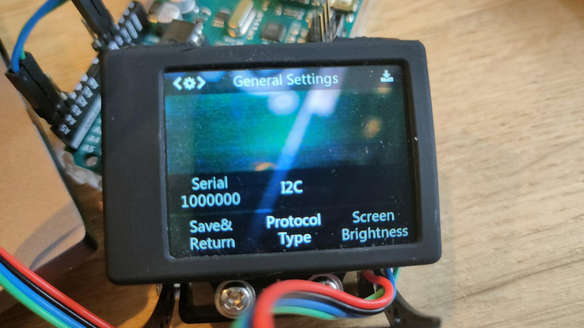
Set your husky protocol to I2C in the settings.
Minimal Code needed
/***************************************************
HUSKYLENS An Easy-to-use AI Machine Vision Sensor
<https://www.dfrobot.com/product-1922.html>
****************************************************/
#include "HUSKYLENS.h"
HUSKYLENS huskylens;
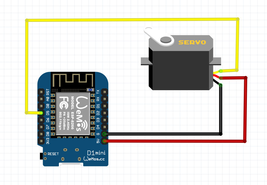
//HUSKYLENS green line >> SDA; blue line >> SCL
int ID0 = 0; //not learned results. Grey result on HUSKYLENS screen
int ID1 = 1; //first learned results. colored result on HUSKYLENS screen
int ID2 = 2; //second learned results. colored result on HUSKYLENS screen
// and so on.....
int arjprevious = 0;
void printResult(HUSKYLENSResult result);
void setup() {
Serial.begin(115200);
Wire.begin();
while (!huskylens.begin(Wire))
{
Serial.println(F("Begin failed!"));
Serial.println(F("1.Please recheck the \"Protocol Type\" in HUSKYLENS (General Settings>>Protocol Type>>I2C)"));
Serial.println(F("2.Please recheck the connection."));
delay(100);
}
huskylens.writeAlgorithm(ALGORITHM_FACE_RECOGNITION);
}
void loop() {
if (huskylens.requestLearned()) //request blocks and arrows tangged ID != 0 from HUSKYLENS
if (huskylens.requestBlocksLearned()) //request blocks tangged ID != ID0 from HUSKYLENS
{
for (int i = 0; i < huskylens.countArrows(ID0); i++)
{
HUSKYLENSResult result = huskylens.getArrow(ID0, i);
}
int arj = huskylens.count(ID1);
if ( arj != arjprevious )
{
if ( arj == 1 )
{
Serial.println("Learned face detected");
}
else
{
Serial.println("Learned face not detected");
}
arjprevious = arj;
}
}
else
{
Serial.println("Fail to request objects from Huskylens!");
}
}
Learned face detected ID1
Learned face not detected
Learned face detected ID1
Learned face not detected
Learned face detected ID1
Learned face not detected