Warning, read the notes!
There are several caveats.
- I was needing ALL GPIO pins, even RX/TX ( see trick below)
When doing so, you can’t use serialprint.
Do NOT enable, your sketch won’t work! - Don’t use pullup on D8, you can’t upload to the wemos if you do that
- Due to library conflicts in keypad.h, DON’T change the order in the source. You will end up with compile errors!
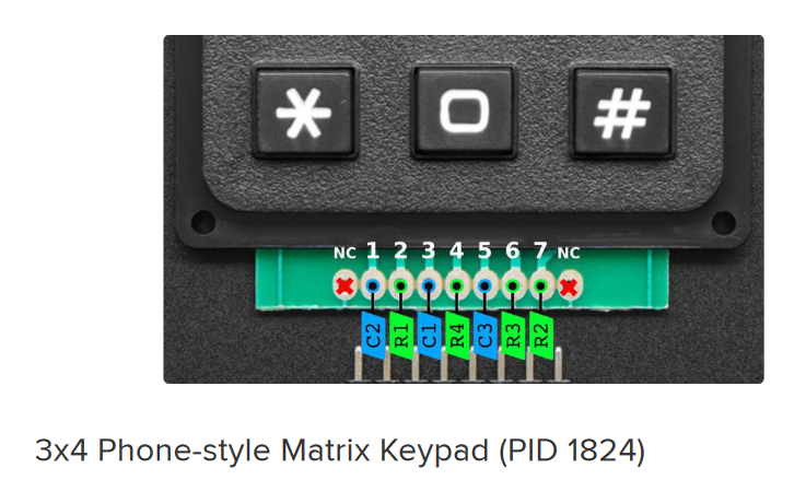
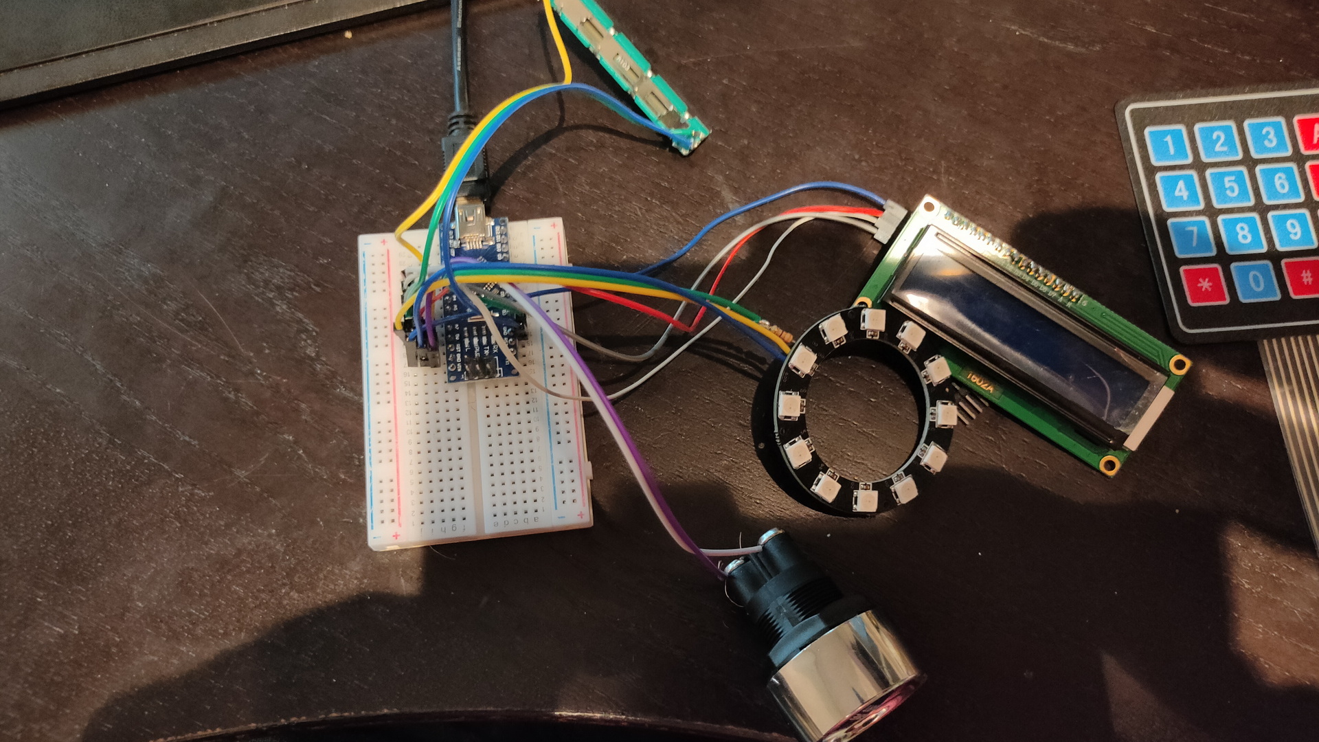
- The keypad has a weird pinout, but there are similar keypads with alternative layouts. Measure this using a multimeter.
- The pull-up resistors will help fighting ghost key presses!
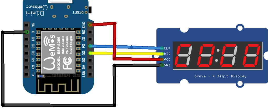
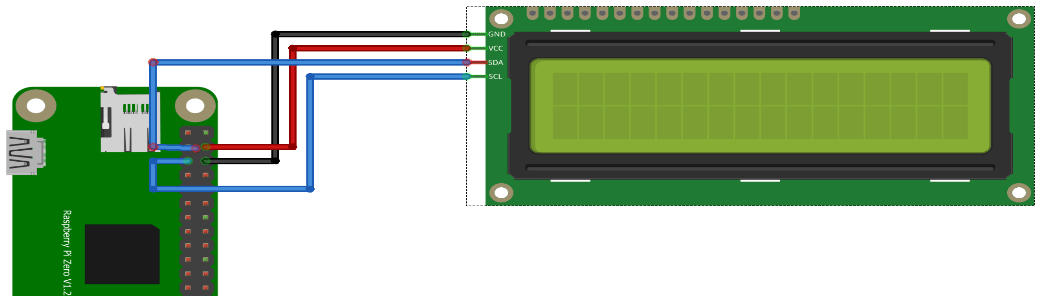
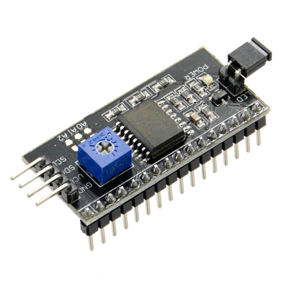
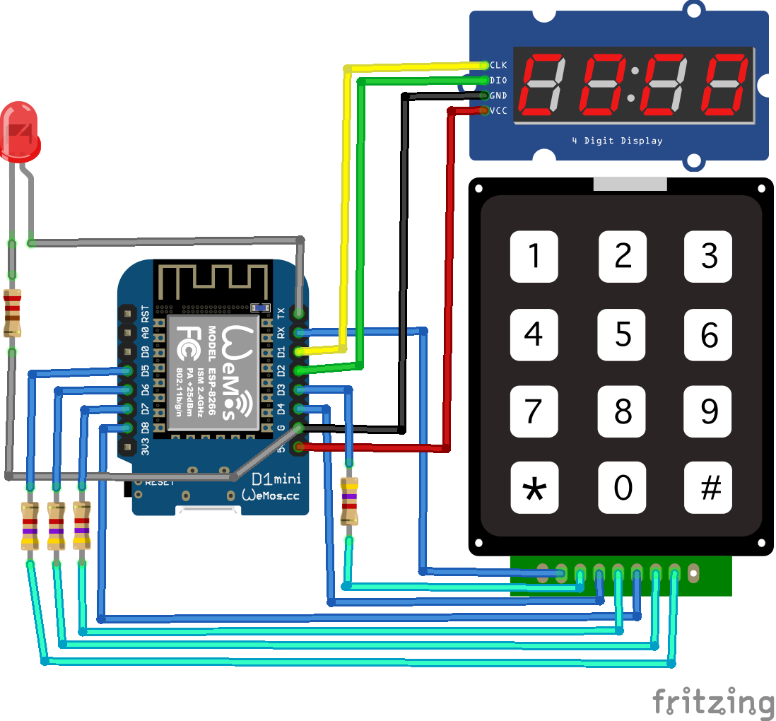
- I2C needs D1/D2
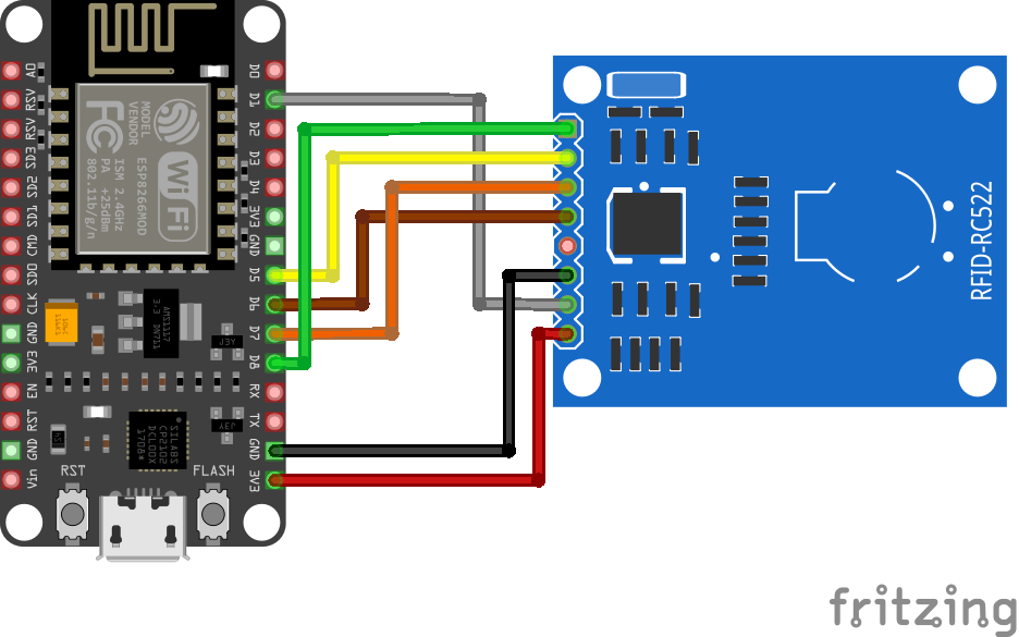
To use RX/TX as GPIO pins you need to do the following:
//Define pins
  int led = 1; //tx
  int col = 3; //rx

// Change to function mode 3
// see https://www.esp8266.com/wiki/doku.php?id=esp8266_gpio_pin_allocations
  pinMode(1, FUNCTION_3);
  pinMode(3, FUNCTION_3);

// Revert to normal mode
// pinMode(1, FUNCTION0);

// Define mode input/output
// i'm using led to control the led so thats an output
// I'm using col for the keypad column scanner, that's an input
  pinMode(led, OUTPUT);
  pinMode(col, INPUT);
Complete code
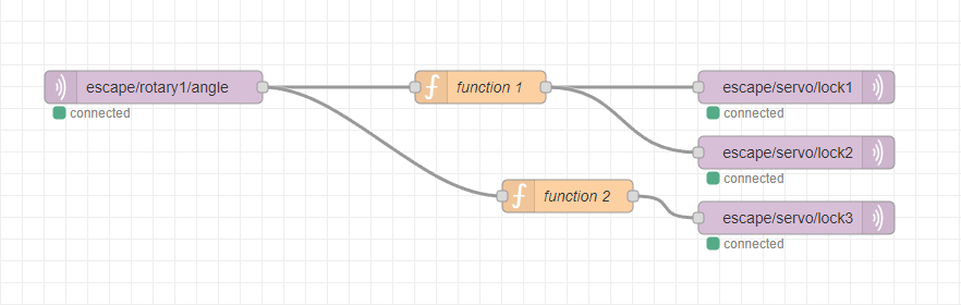
The (*) clears input
The (#) sends the pin code using MQTT
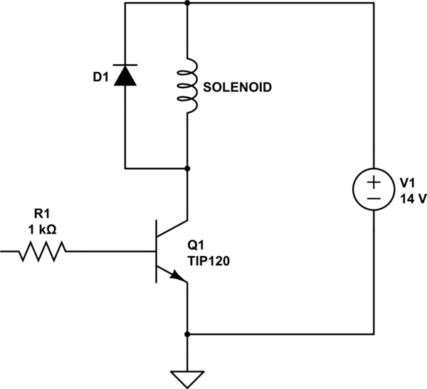
Sending a 0 or 1 to escape/keypadin topic will toggle the led
#include <ESP8266WiFi.h>
#include <PubSubClient.h>
#include <WiFiClient.h>
// Do not change order!
#include "Keypad.h"
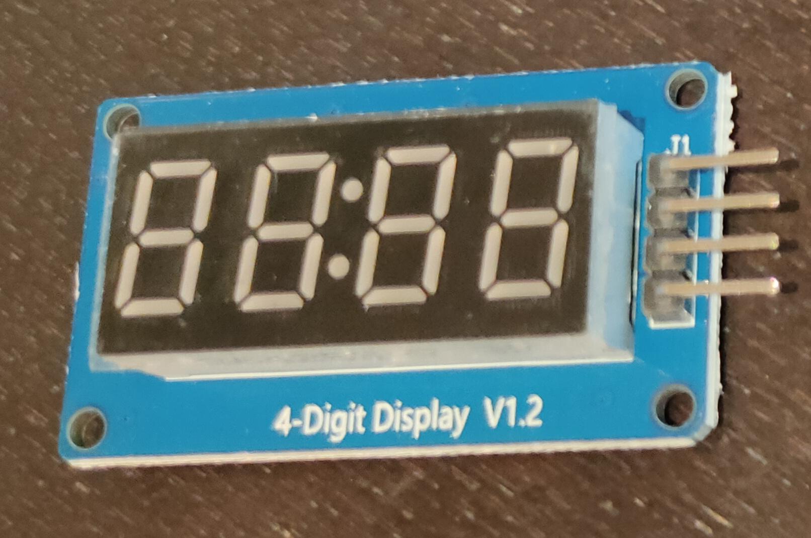
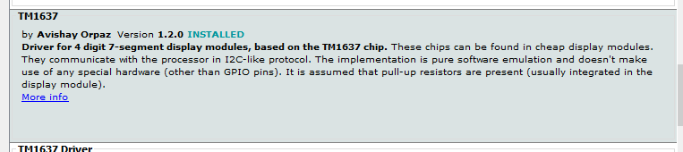
#include <TM1637Display.h>
#include <Ethernet.h>
#define wifi_ssid "SSID"
#define wifi_password "SSIDPASS"
#define mqtt_server "MQTTSERVER"
#define mqtt_port 1883
#define MSG_BUFFER_SIZE (50)
char msg[MSG_BUFFER_SIZE];
int value = 0;
const byte ROWS = 4; //four rows
const byte COLS = 3; //four columns
int led = 1; //tx
int col = 3; //rx
#define CLK D1
#define DIO D2
#define TEST_DELAY 2000
TM1637Display display(CLK, DIO);
char keys[ROWS][COLS] = {
{'1', '2', '3'},
{'4', '5', '6'},
{'7', '8', '9'},
{'*', '0', '#'}
};
byte rowPins[ROWS] = {D3, D5 , D6 , D7 };
byte colPins[COLS] = {D4 , col, D8 };
Keypad keypad = Keypad(makeKeymap(keys), rowPins, colPins, ROWS, COLS);
int keyNum = 0;
WiFiClient espClient;
EthernetClient ethClient;
PubSubClient mqtt(espClient);
void setup_wifi() {
delay(10);
WiFi.mode(WIFI_STA);
WiFi.begin(wifi_ssid, wifi_password);
while (WiFi.status() != WL_CONNECTED) {
delay(500);
}
}
void setup() {
setup_wifi();
mqtt.setServer(mqtt_server, mqtt_port);
mqtt.setCallback(callback);
pinMode(1, FUNCTION_3);
pinMode(3, FUNCTION_3);
pinMode(led, OUTPUT);
pinMode(col, INPUT);
// using above? .. then disable serial!
// Serial.begin(9600);
display.showNumberDec(0, true);
delay(TEST_DELAY);
WiFiClient espClient;
PubSubClient mqtt(espClient);
mqtt.setClient(espClient);
mqtt.setServer(mqtt_server, 1883);
mqtt.setCallback(callback);
mqtt.subscribe("escape/keypadin");
}
void callback(char* topic, byte* payload, unsigned int length) {
// digitalWrite(led, HIGH);
String topicStr = topic;
byte value = atoi((char*)payload);
if (value == 1){
digitalWrite(led, HIGH);
}else if (value == 0){
digitalWrite(led, LOW);
}
}
void reconnect() {
while (!mqtt.connected()) {
// Create a random client ID
String clientId = "ESP8266Client-";
clientId += String(random(0xffff), HEX);
if (mqtt.connect(clientId.c_str())) {
mqtt.publish("outTopic", "hello world");
mqtt.subscribe("escape/keypadin");
} else {
delay(5000);
}
}
}
void loop() {
if (!mqtt.connected()) {
reconnect();
}
mqtt.loop();
// put your main code here, to run repeatedly:
char key = keypad.getKey();
if (key) {
if(key=='*'){
keyNum = 0;
} else if (key=='#'){
++value;
snprintf (msg, MSG_BUFFER_SIZE, "#%1d", keyNum);
mqtt.publish("escape/keypad", msg);
}
else{
if(keyNum<=999){
keyNum = (keyNum*10) + (int(key)-48);
}
}
// Serial.println(key);
display.setBrightness(0x0f);
uint8_t data[] = { 0x0, 0x0, 0x0, 0x0 };
display.setSegments(data);
display.setSegments(data);
display.showNumberDec(keyNum);
}
}