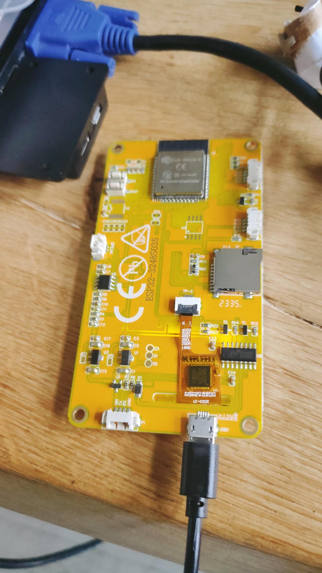
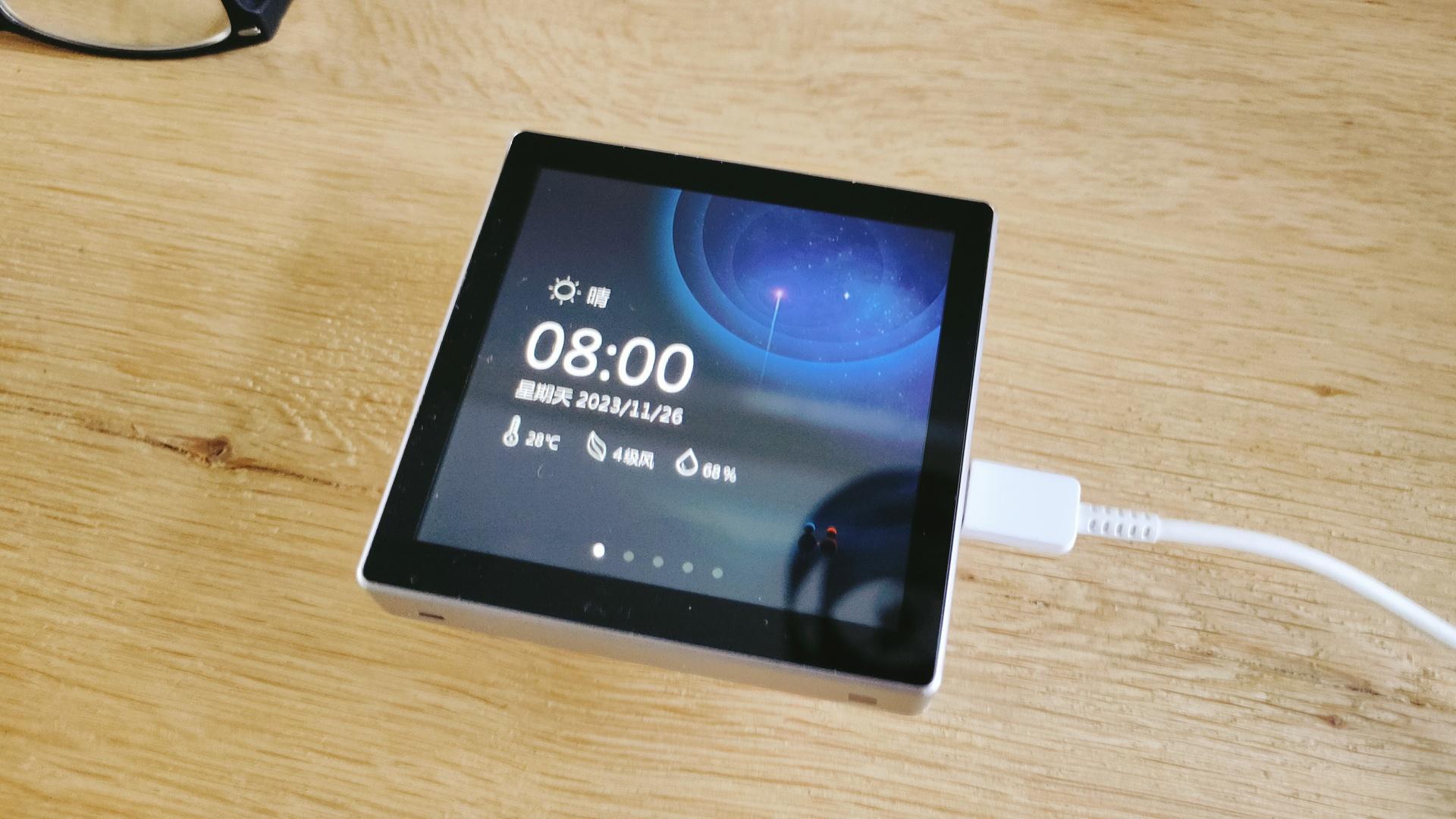
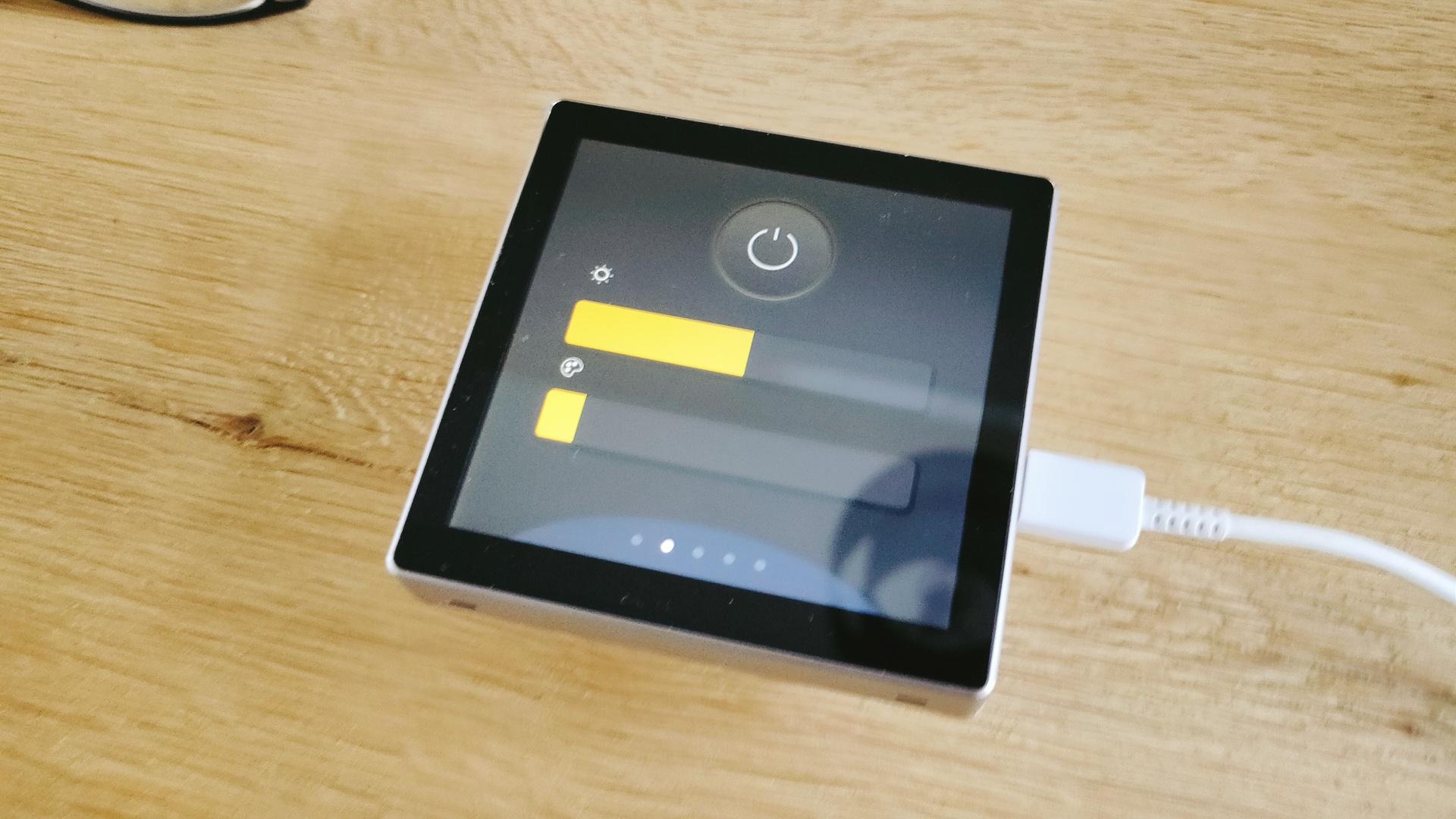
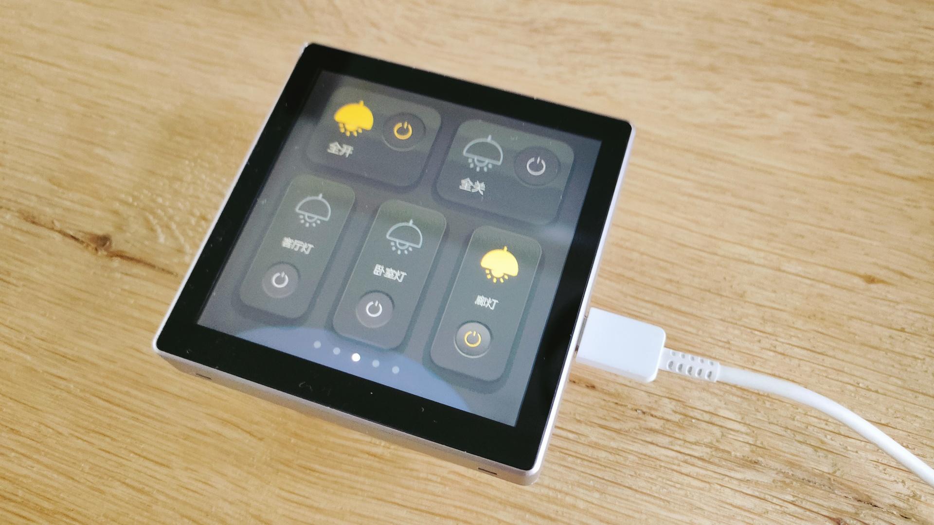
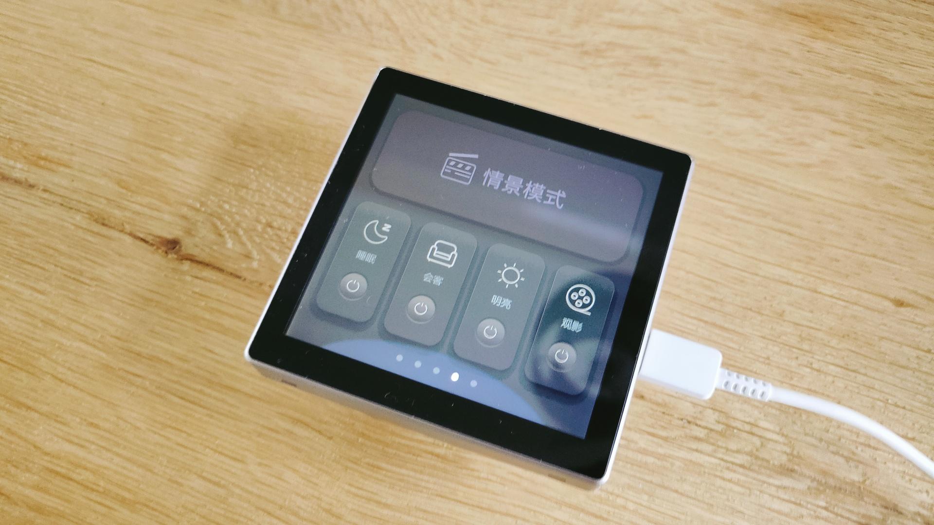
Jingcai/Sunton ESP32-3248S035C – 3.5 inch TFT Display 320*480 pixels with Capacitive Touchscreen – ESP32
An even cheaper solution than post below.
Printed a nice case, let the designing begin.
Jingcai/Sunton ESP32-3248S035C – 3.5 inch TFT Display 320*480 pixels with Capacitive Touchscreen – ESP32
An even cheaper solution than post below.
Printed a nice case, let the designing begin.
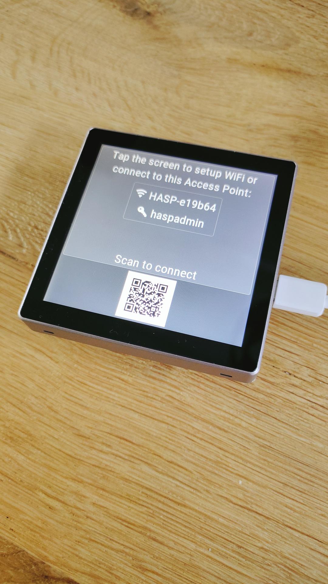
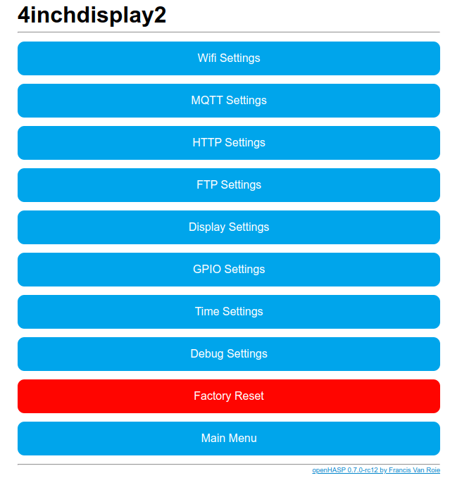
I bought a cheap esp32 display (4 inch 480×480) from China.
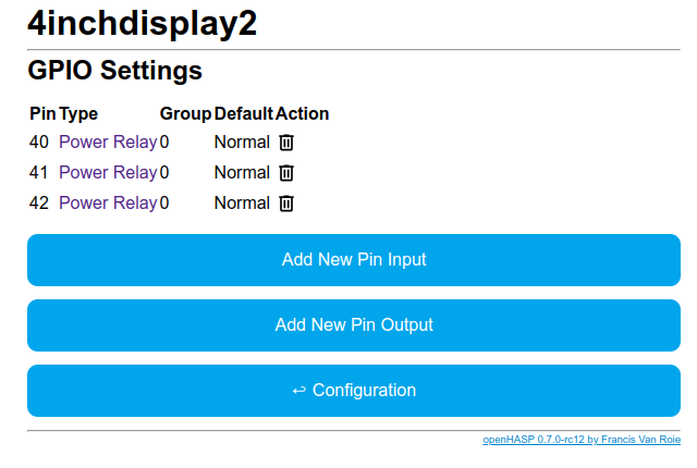
It also has three relays to control lights.
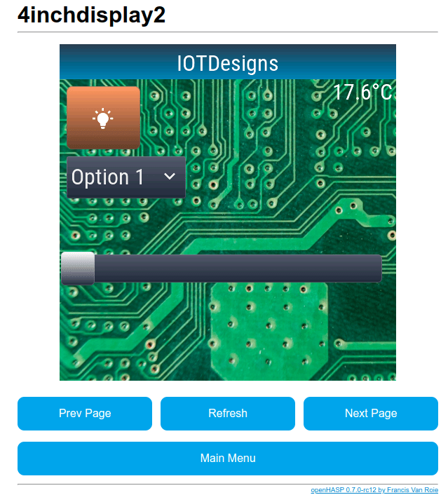
Below is a gallery with default screens.
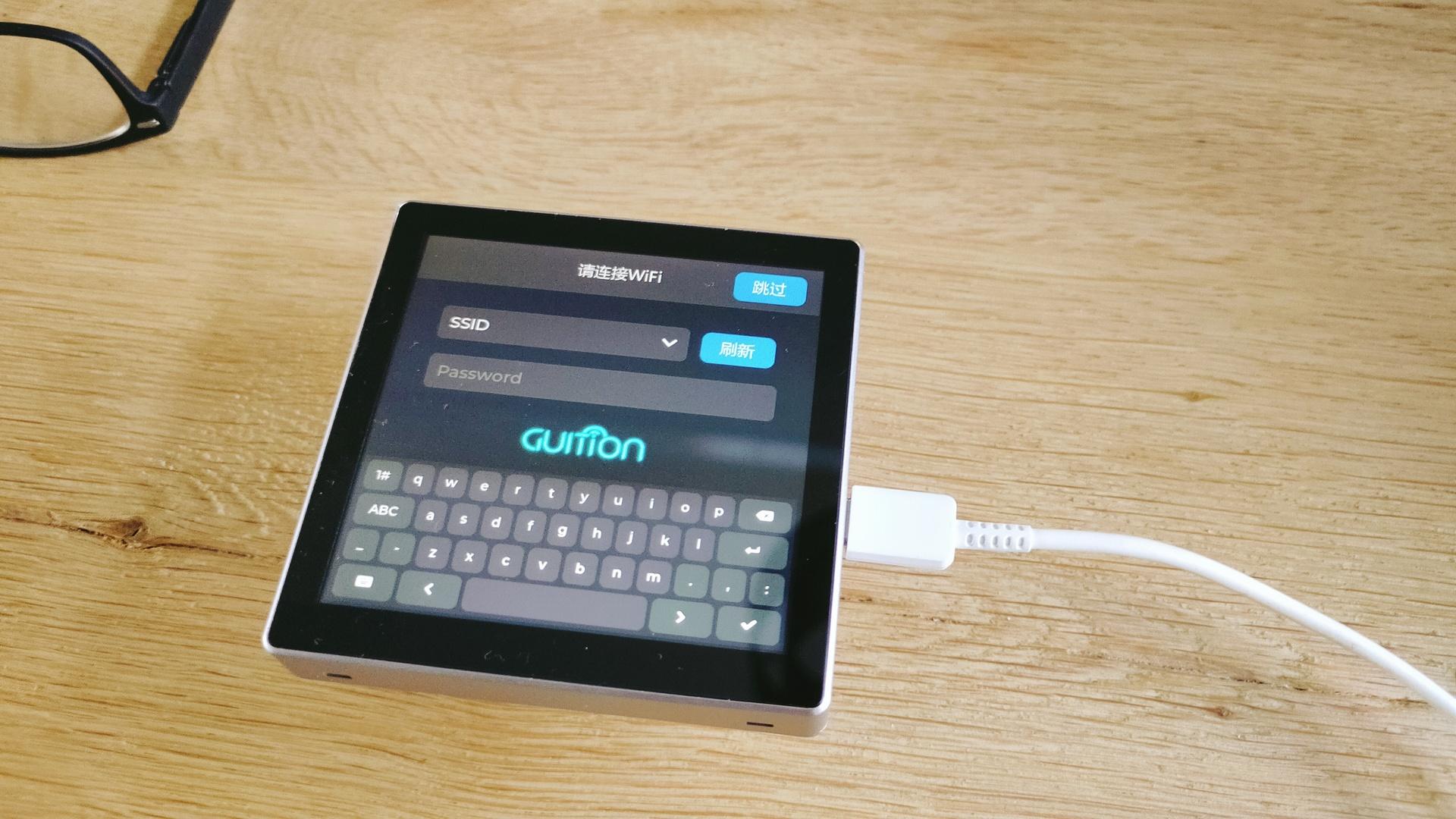
Flashing OpenHasp was a breeze.
Configure the thing for HA was not so easy.
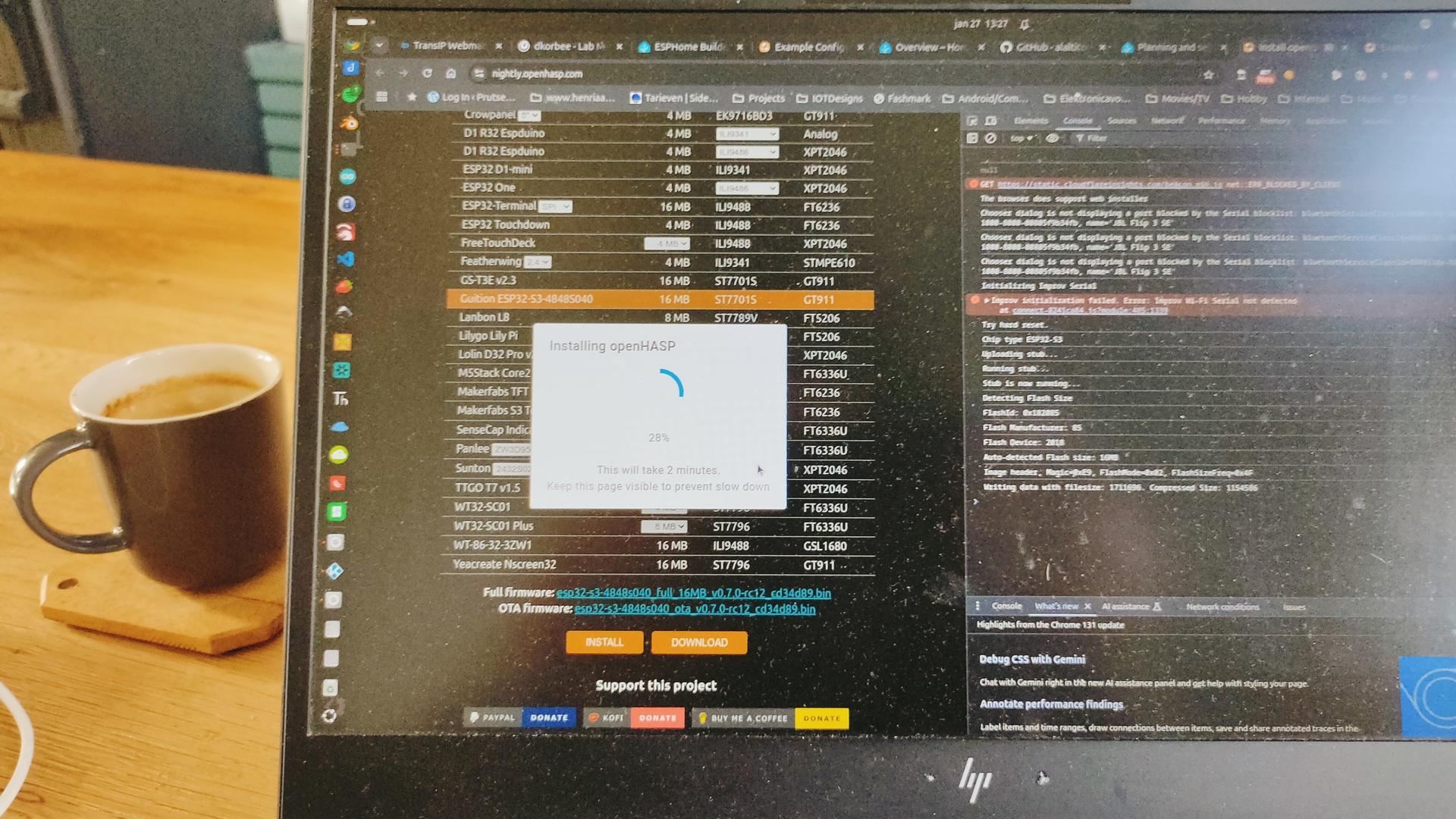
Install OpenHasp via Hacs on HA.
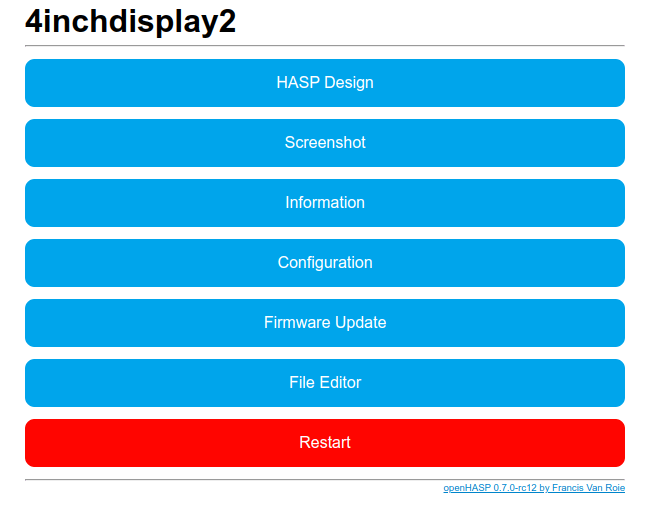
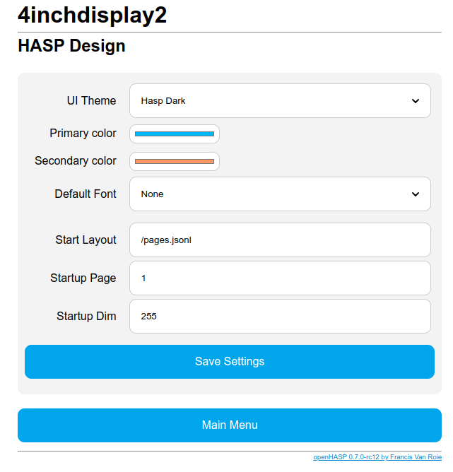
There is a webinterface on the display, here you have to configure wifi, mqtt and the pages.
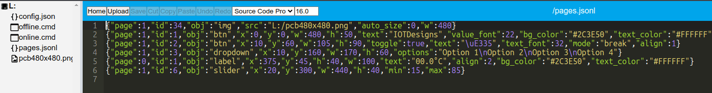
Config files used for this first test:
{"page":1,"id":34,"obj":"img","src":"L:/pcb480x480.png","auto_size":0,"w":480}
{"page":1,"id":1,"obj":"btn","x":0,"y":0,"w":480,"h":50,"text":"IOTDesigns","value_font":22,"bg_color":"#2C3E50","text_color":"#FFFFFF","radius":0,"border_side":0}
{"page":1,"id":2,"obj":"btn","x":10,"y":60,"w":105,"h":90,"toggle":true,"text":"\uE335","text_font":32,"mode":"break","align":1}
{"page":1,"id":3,"obj":"dropdown","x":10,"y":160,"w":170,"h":60,"options":"Option 1\nOption 2\nOption 3\nOption 4"}
{"page":0,"id":1,"obj":"label","x":375,"y":45,"h":40,"w":100,"text":"00.0°C","align":2,"bg_color":"#2C3E50","text_color":"#FFFFFF"}
{"page":1,"id":6,"obj":"slider","x":20,"y":300,"w":440,"h":40,"min":15,"max":85}
Designer at : https://haspdesigner.qrisonline.nl/
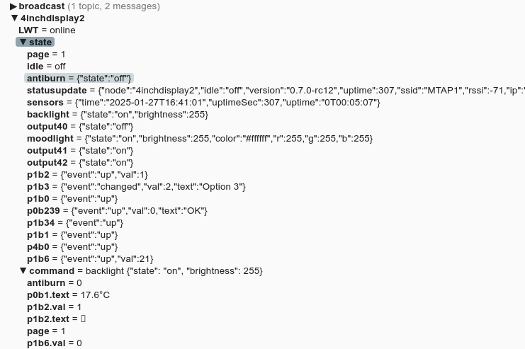
4inchdisplay2:
    objects:
      - obj: "p0b1"  # temperature label on all pages
        properties:
          "text": '{{ states("sensor.livingtemperature") }}°C'
      - obj: "p1b2"  # light-switch toggle button
        properties:
          "val": '{{ 1 if states("switch.livingshelly") == "on" else 0 }}'
          "text": '{{ "\uE6E8" if is_state("switch.livingshelly", "on") else "\uE335" | e }}'
        event:
          "up":
            - service: homeassistant.toggle
              entity_id: "switch.livingshelly"
      - obj: "p1b3"  # dropdown
        event:
          "changed":
            - service: persistent_notification.create
              data:
                message: I like {{ text }}
      - obj: "p1b6" # Light brightness
        properties:
          "val": "{{ state_attr('number.dinnertable_brightness_0', 'brightness') if state_attr('number.dinnertable_brightness_0', 'brightness') != None else 0 }}"
        event:
          "changed":
            - service: light.turn_on
              data:
                entity_id: number.dinnertable_brightness_0
                brightness:  "{{ val }}"
          "up":
            - service: light.turn_on
              data:
                entity_id: number.dinnertable_brightness_0
                brightness:  "{{ val }}"
NOTE: Dimmer is not working via HA (yet), but mqtt messages are working.
| obj | Type | Description | Extra Parts |
|---|---|---|---|
| btn | Binary | Button | |
| switch | Toggle | Switch | indicator, knob |
| checkbox | Toggle | Checkbox | indicator |
| label | Visual | Label | |
| led | Visual | LED | |
| spinner | Visual | Spinner | indicator |
| obj | Visual | Base Object | |
| line | Visual | Line | |
| img | Visual | Image | |
| cpicker | Selector | Color picker | knob |
| roller | Selector | Roller | selected |
| dropdown | Selector | Dropdown List | selected, items, scrollbar |
| btnmatrix | Selector | Button Matrix | items |
| msgbox | Selector | Messagebox | items, items_bg |
| tabview | Selector | Tabview | items, items_bg, indicator, selected |
| tab | Selector | Tab | |
| bar | Range | Progress Bar | indicator |
| slider | Range | Slider | indicator, knob |
| arc | Range | Arc | indicator, knob |
| linemeter | Range | Line Meter | |
| gauge | Range | Gauge | indicator, ticks |
| qrcode | Visual | Qrcode |
I’ve got a flipper zero at last.
https://flipperzero.one/
I know, it’s more an useful toy than a serious tool.
It’s too limited. But useful for me.
Learning about tools and sub gigahertz monitoring.
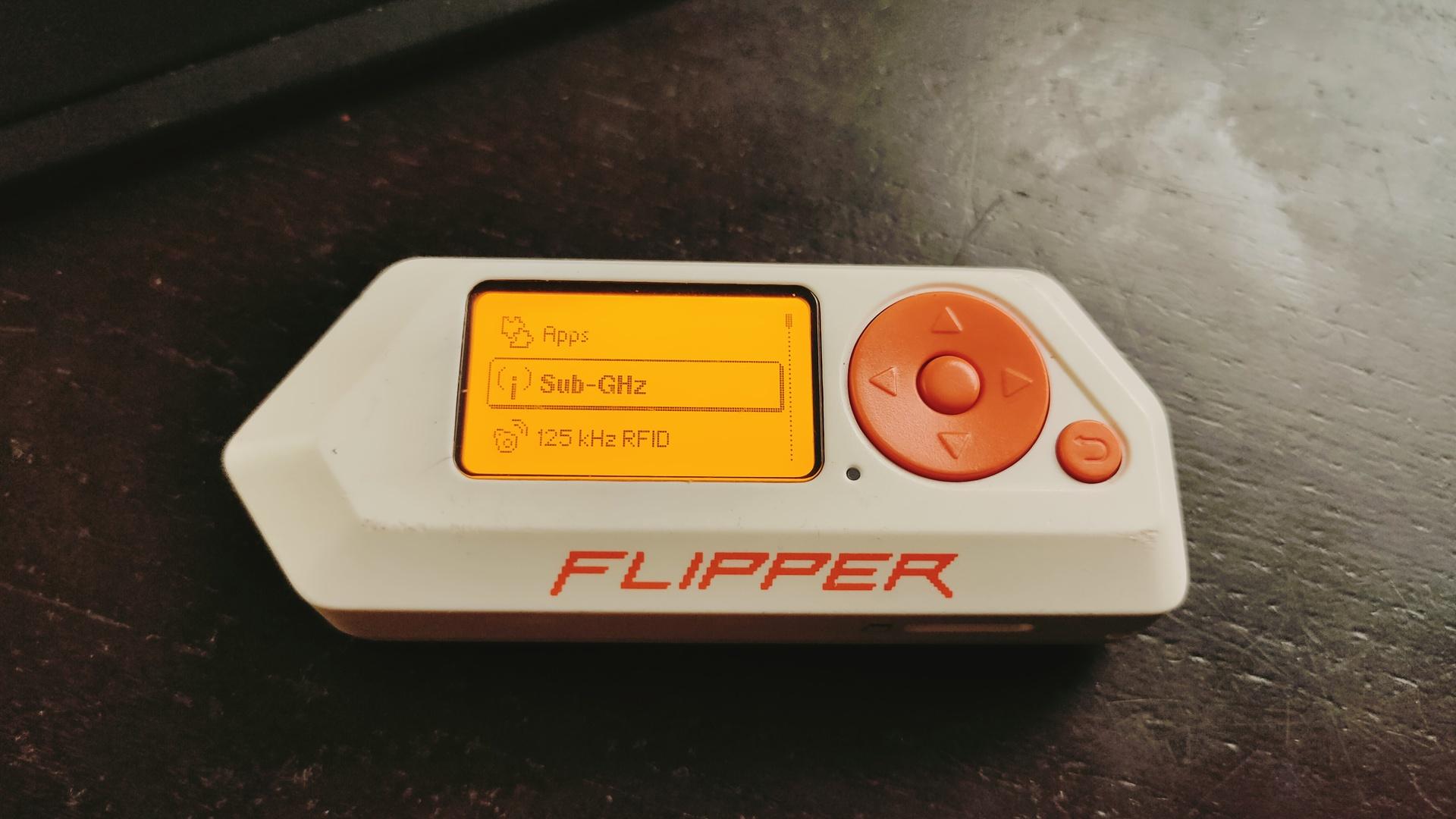
I hoped to get a BFFB for it, that will be a big plus.
https://www.justcallmekokollc.com/product/flipper-zero-bffb/31
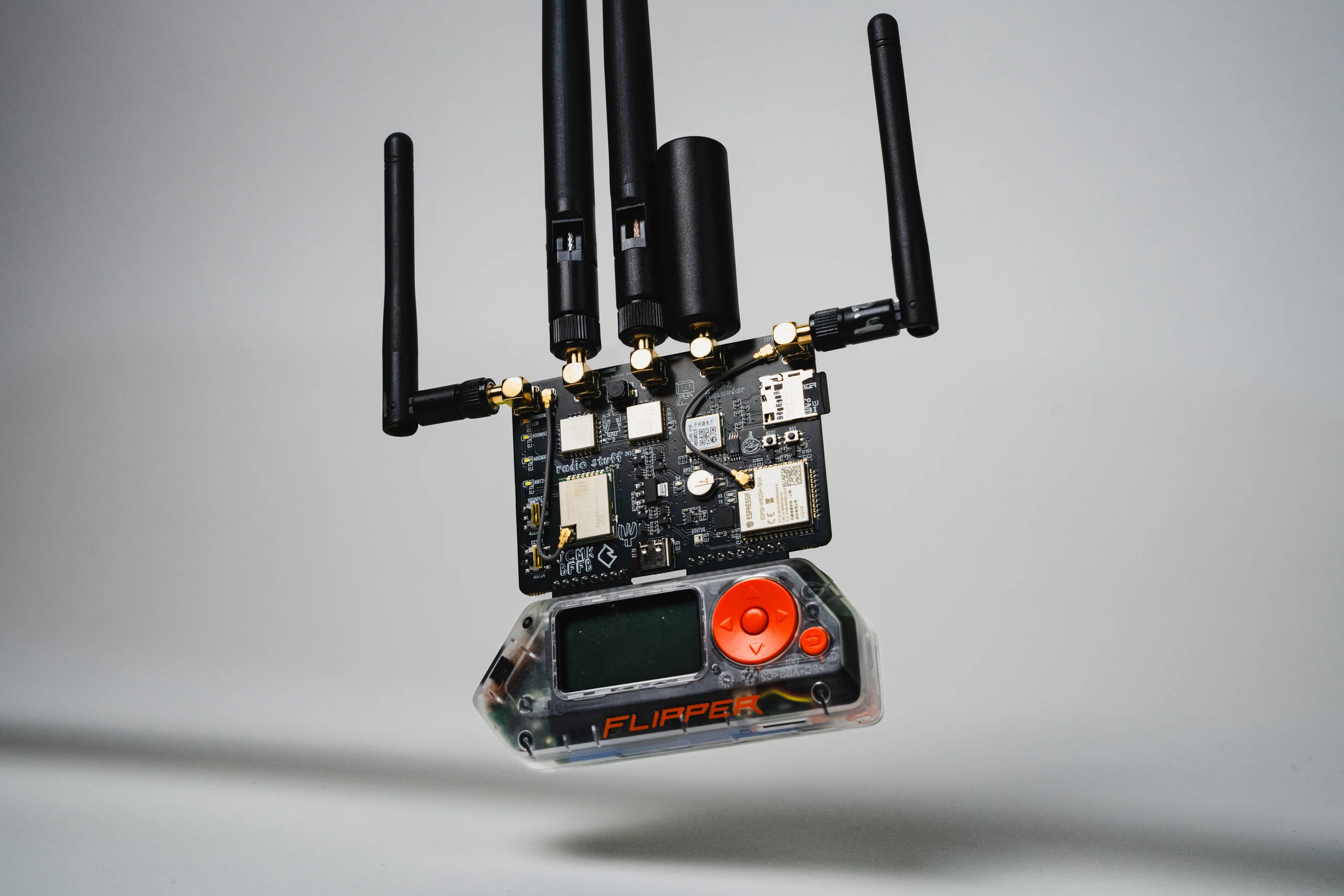
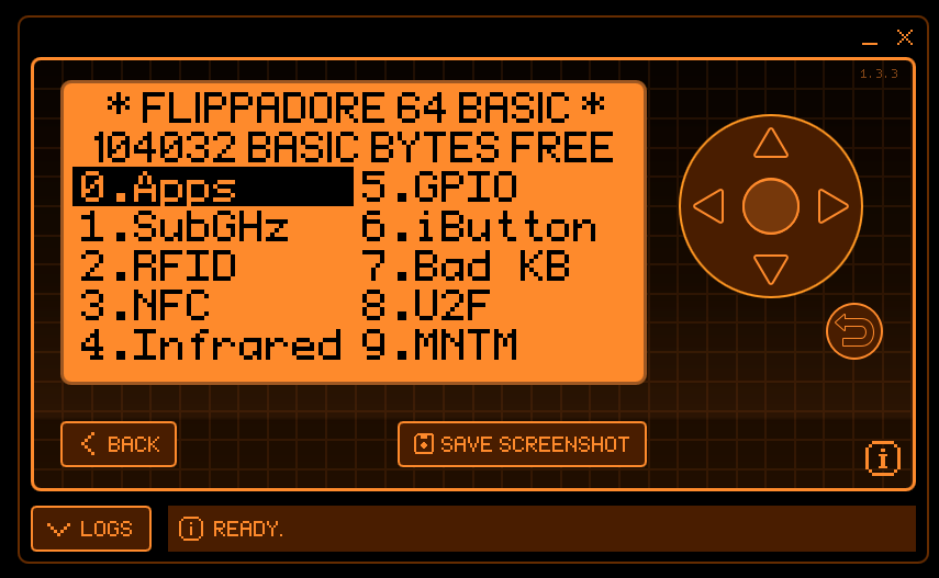
One of the first things was reflashing the device with Momentum firmware.
I’ve ordered a Wi-Fi Dev Board, so I can use Marauder.
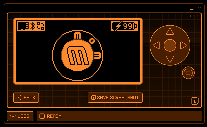
Here are some qFlipper screenshots.
Will add pictures and info about the Wifi dev board.
Some information:
The Flipper Zero is a versatile multi-tool for geeks, hackers, and hardware enthusiasts. It is designed as a portable, open-source device with numerous capabilities for interacting with digital systems and hardware. Here’s an overview of what the Flipper Zero can do:
The Flipper Zero is a powerful tool, but its legality depends on how it is used. Be sure to respect laws and ethical guidelines when exploring its capabilities.
To display quotes, changing once per hour.
There is not much to be found for Waveshare 4.2 Epaper.
Except for an Arduino web example.
( see https://www.waveshare.com/wiki/E-Paper_ESP32_Driver_Board )
I reversed engineered the workings, and created a python upload script to push images.
Original workings are a mess.
Per 4 bit of color, high-low switched in a byte.
Black and red separated.
Using a till p encoding over curl commands.
My implementation uses a python script called as:
python3 epaper-pusher.py ~/Downloads/Untitled.png

http://10.1.0.99/EPDI_
30 times something like
http://10.1.0.99/ppppppppppppppppppppppppppppppppppppppppppppppppppppppaaaaaaaaaaaaaaaaaaaaaaaaaaaaaaaaaaaaaaaaaaaaaaaaaaaaaaaaaaaaabbbbbbbbbbbbbbbbppppppppppppppppppppppppppppppppppppppppppppppppppppppppppppppppppppppppppppppppppppppppppppppppppppppppppppppppppppppppppppppppppppppppppppppppppppppppppppppppppppppppppppppppppppppppppppppppppppppppppppppppppppppppppppppppppppppppppppppppppppppppppppppppppppppppppppppppppppppppppppppppppppppppppppppppppppppppppppppppppppppppppppppppppppppppppppppppppppppppppppppppppppppppppppppppppppppppppppppppppppppppppppppppppppppppppppppppppppppppppppppppppppppppppppppppppppppppppppppppppppppppppppppppppppppppppppppppppppppppppppppppppppppppppppppppppppppppppppppppppppppppppppppppppppppppppppppppppppppppppppppppppppppppppppppppppppppppppppppppppppppppppppppppppppppppppppppppppppppppppppppppppppppppppppppppppppppppppppppppppppppppppppppppppppppppppppppppppppppppppppppppppppppppppppppppppppppppppppppppppppppppppppppppppppppppppppppppppppppppppppppppppppppppppppppppppppiodaLOAD_
http://10.1.0.99/NEXT_
30 times something like
http://10.1.0.99/pbcdefghijjjjjjffffffoooooooaaabbbbbbeeeedddppppppppppppppppppppppppppppppppppppppppppppppppppppppppppppppppppppppppppppppppppppppppppppppppppppppppppppppppppppppppppppppppppppppppppppppppppppppppppppppppppppppppppppppppppppppppppppppppppppppppppppppppppppppppppppppppppppppppppppppppppppppppppppppppppppppppppppppppppppppppppppppppppppppppppppppppppppppppppppppppppppppppppppppppppppppppppppppppppppppppppppppppppppppppppppppppppppppppppppppppppppppppppppppppppppppppppppppppppppppppppppppppppppppppppppppppppppppppppppppppppppppppppppppppppppppppppppppppppppppppppppppppppppppppppppppppppppppppppppppppppppppppppppppppppppppppppppppppppppppppppppppppppppppppppppppppppppppppppppppppppppppppppppppppppppppppppppppppppppppppppppppppppppppppppppppppppppppppppppppppppppppppppppppppppppppppppppppppppppppppppppppppppppppppppppppppppppppppppppppppppppppppppppppppppppppppppppppppppppppppppppppppppppppppppppppppppppppppppppppppppppppppppppppppppppppppppppppppppppppppppppppppppppppppppppppppppppppppppppiodaLOAD_
http://10.1.0.99/SHOW_
NOTES:
a = 0000
-
-
-
p = 1111 = 15

30 lines with 1000 bytes ( ending with iodaLOAD_ )

black pixels
first block 1
second block 0

red pixels
first block 0
second block 1

white pixels
first block 1
second block 1

PIXEL Example
RBRB
BWBW

First block
1010 - letter K
0101 - Letter F - second nibble = white

Second block
0101 - Letter F
1111 - Letter P - second nibble white
Code
from PIL import Image
import numpy
import requests

url="http://10.1.0.99/"

black_pixels = numpy.zeros((400,300))
red_pixels = numpy.zeros((400,300))


def classify_pixel_color(pixel):
    """
    Classify a pixel as black, white, or red.
    """
    r, g, b = pixel[:3]  # Ignore alpha if present

    # Define thresholds for classification
    if r < 128 and g < 128 and b < 128:
        return 'black'
    elif r > 200 and g > 200 and b > 200:
        return 'white'
    elif r > 128 and g < 100 and b < 100:
        return 'red'
    else:
        return None

def process_image(image_path):
    """
    Process the image and classify its pixels into black, white, or red.
    """
    image = Image.open(image_path)
    image = image.convert("RGB")  # Ensure the image is in RGB mode

    width, height = image.size
    pixel_data = image.load()

    color_counts = {'black': 0, 'white': 0, 'red': 0}

    for y in range (0, 299):
        for x in range (0, 399):
            black_pixels[x][y] = 0
            red_pixels[x][y] = 0

    for y in range(299):
        for x in range(399):
            color = classify_pixel_color(pixel_data[x, y])
            if color:
                color_counts[color] += 1
                if color == 'black':
                    black_pixels[x][y] = 1;
                if color == 'red':
                    red_pixels[x][y] = 1;
                if color == 'white':
                    black_pixels[x][y] = 1;
                    red_pixels[x][y] = 1;

    return color_counts, black_pixels, red_pixels

def number_to_letter(num):
    """
    Translates a number from 0 to 15 into a corresponding letter (a-p).

    Args:
        num (int): The number to translate.

    Returns:
        str: The corresponding letter (a-p).
    """
    if 0 <= num <= 15:
        return chr(ord('a') + num)
    else:
        raise ValueError("Number must be between 0 and 15, inclusive.")

def print_array_in_chunks(array, chunk_size=1001):
    current_chunk = ""
    for item in array:
        # Convert item to string and add to the current chunk
        item_str = str(item)
        if len(current_chunk) + len(item_str) + 1 > chunk_size:
            # Print the current chunk and reset it
            current_chunk += "iodaLOAD_"
            try:
                requests.get(url + current_chunk, verify=False)
                if not response.content:  # Equivalent to expecting an empty reply
                    pass
            except requests.exceptions.RequestException as e:
                # Catch any request-related errors
                pass
            current_chunk = item_str
        else:
            # Append the item to the current chunk
            current_chunk += (item_str)
    current_chunk += "iodaLOAD_"
    # Print any remaining items in the chunk
    if current_chunk:
        try:
            requests.get(url + current_chunk, verify=False)
            if not response.content:  # Equivalent to expecting an empty reply
                pass
        except requests.exceptions.RequestException as e:
            # Catch any request-related errors
            pass


def switch_in_pairs(arr):
    # Loop through the array with a step of 2
    for i in range(0, len(arr) - 1, 2):
        # Swap values at index i and i+1
        arr[i], arr[i + 1] = arr[i + 1], arr[i]
    return arr

if __name__ == "__main__":
    import sys

    if len(sys.argv) < 2:
        print("Usage: python3 script.py <image_path>")
        sys.exit(1)

    image_path = sys.argv[1]
    try:
        color_counts, black_pixels, red_pixels = process_image(image_path)
        try:
            requests.get(url + "EPDI_" , verify=False)
            if not response.content:  # Equivalent to expecting an empty reply
                pass
        except requests.exceptions.RequestException as e:
            # Catch any request-related errors
            pass


        lines=[]
        for y in range(300):
            for x in range(0,399,4):
                first = red_pixels[x][y]
                second = red_pixels[x+1][y]
                thirth = red_pixels[x+2][y]
                fourth = red_pixels[x+3][y]
                nibble = 0
                if (first ==  1):
                        nibble = nibble + 8
                if (second ==  1):
                        nibble = nibble + 4
                if (thirth ==  1):
                        nibble = nibble + 2
                if (fourth ==  1):
                        nibble = nibble + 1
                lines.append(number_to_letter(nibble))
        switched_array = switch_in_pairs(lines)
        print_array_in_chunks(switched_array)
        try:
            requests.get(url + "NEXT_" , verify=False)
            if not response.content:  # Equivalent to expecting an empty reply
                pass
        except requests.exceptions.RequestException as e:
            # Catch any request-related errors
            pass
        lines=[]
        for y in range(300):
            for x in range(0,399,4):
                first = black_pixels[x][y]
                second = black_pixels[x+1][y]
                thirth = black_pixels[x+2][y]
                fourth = black_pixels[x+3][y]
                nibble = 0
                if (first ==  1):
                        nibble = nibble + 8
                if (second ==  1):
                        nibble = nibble + 4
                if (thirth ==  1):
                        nibble = nibble + 2
                if (fourth ==  1):
                        nibble = nibble + 1
                lines.append(number_to_letter(nibble))
        switched_array = switch_in_pairs(lines)
        print_array_in_chunks(switched_array)

        try:
            requests.get(url + "SHOW_" , verify=False)
            if not response.content:  # Equivalent to expecting an empty reply
                pass
        except requests.exceptions.RequestException as e:
            # Catch any request-related errors
            pass

    except Exception as e:
        pass
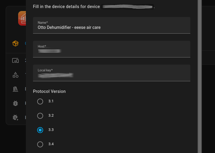
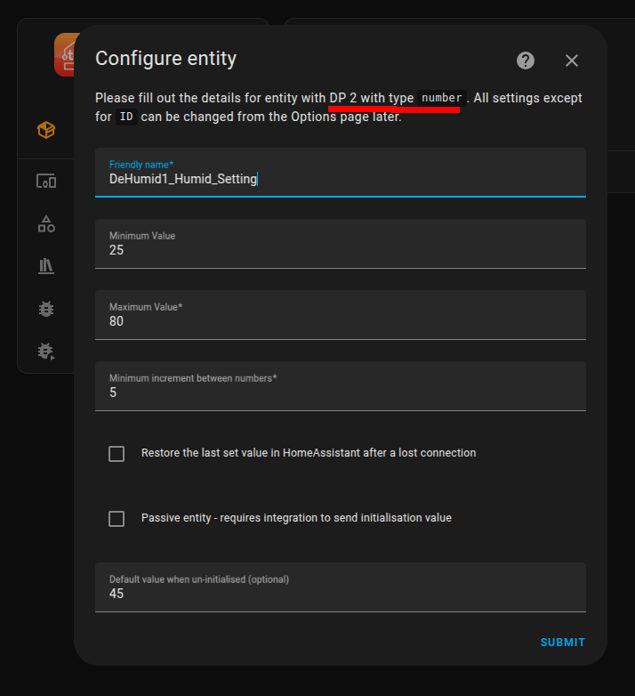
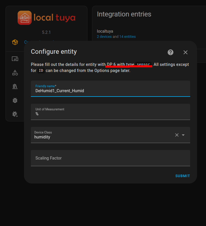
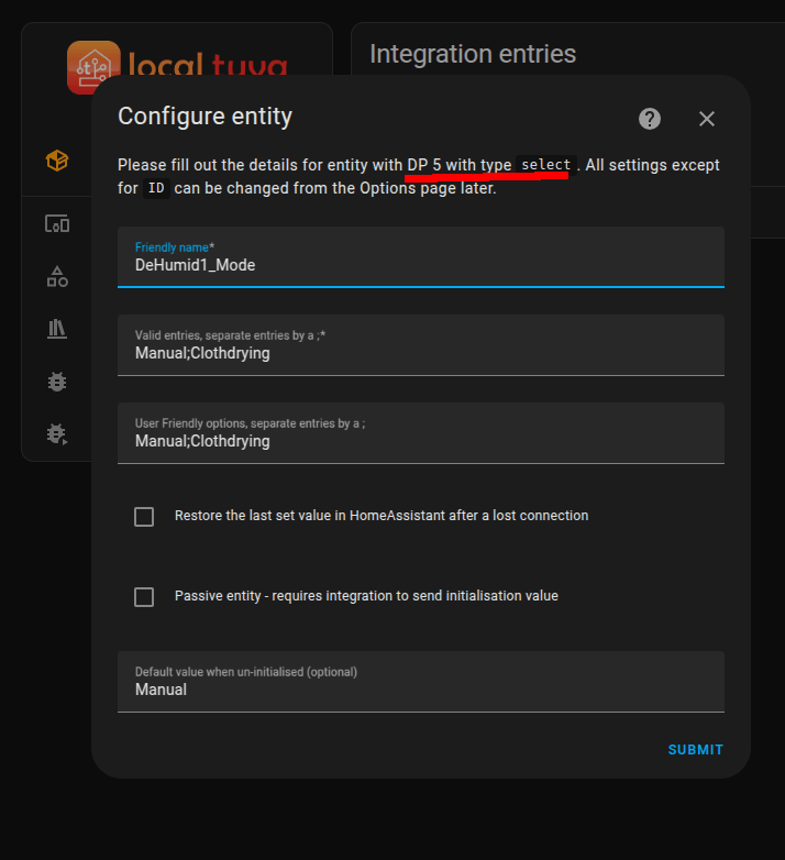
A while ago, I bought a small Dehumidifier for my wine cellar.
I liked it a lot, so I bought another for our bedroom.
I saw some posts about people asking which Dehumidifier is supported by Home Assistant.
This one is. The “Eeese Otto Dehumidifier”
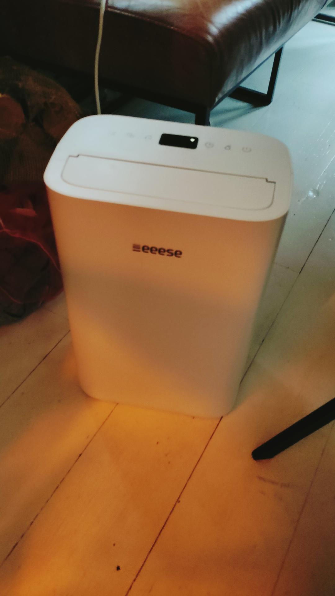
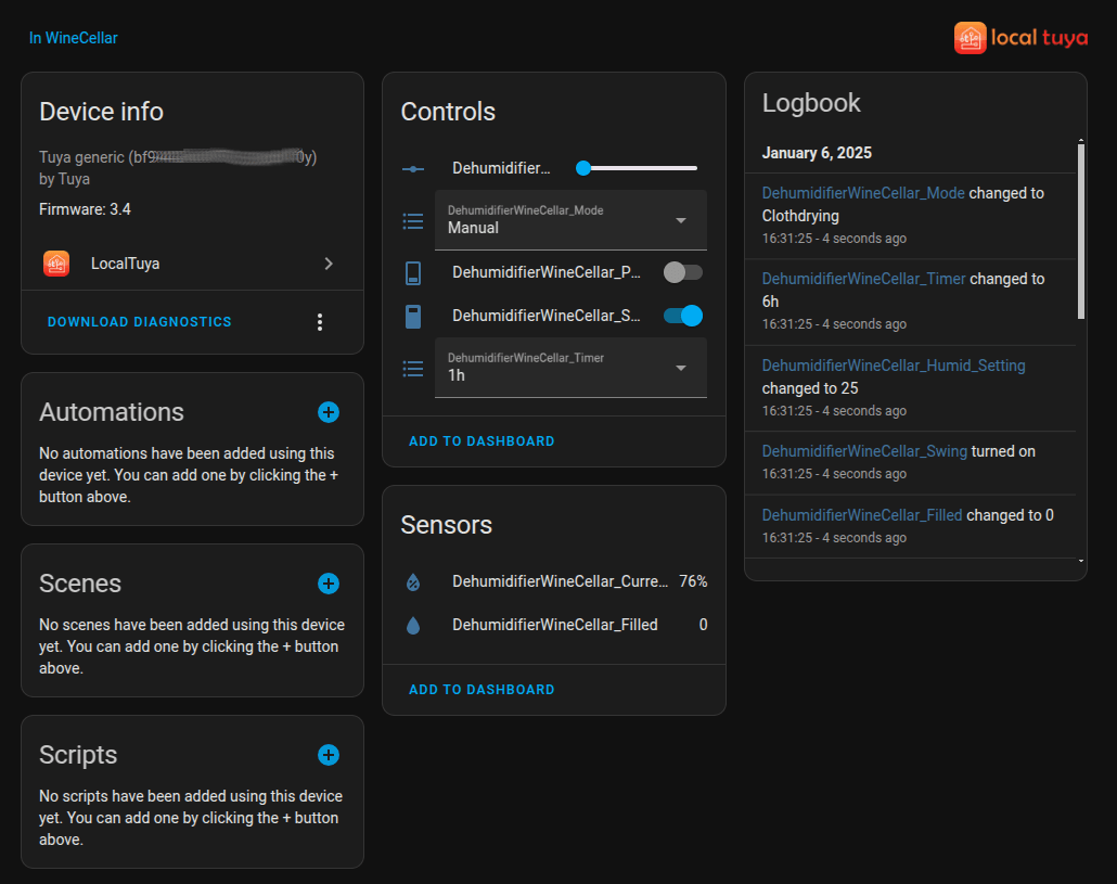
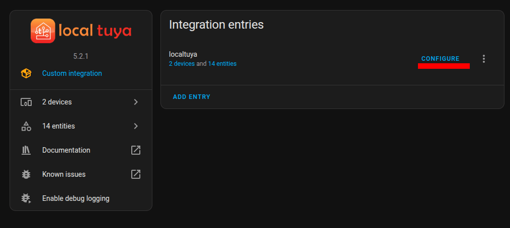
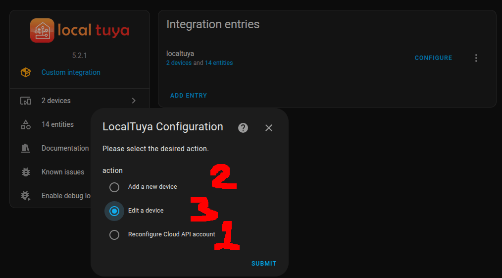
This works with the LocalTuya integration.
There are many examples how to integrate LocalTuya in HA which can be found easily using a search on the net. So, I’m not going to explain that.
I could not find a configuration example, that’s why I’ll post that part here.
Pre config:
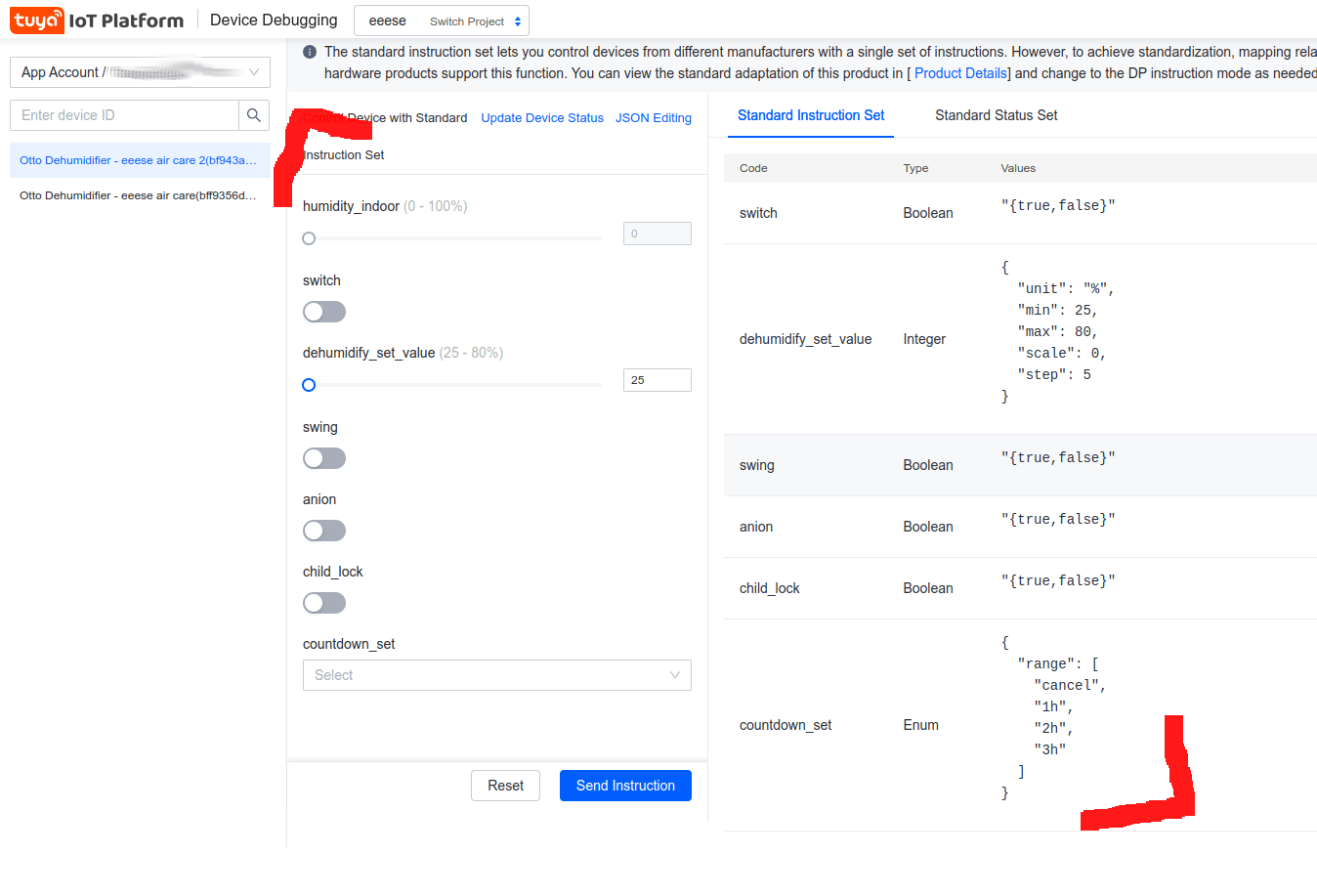
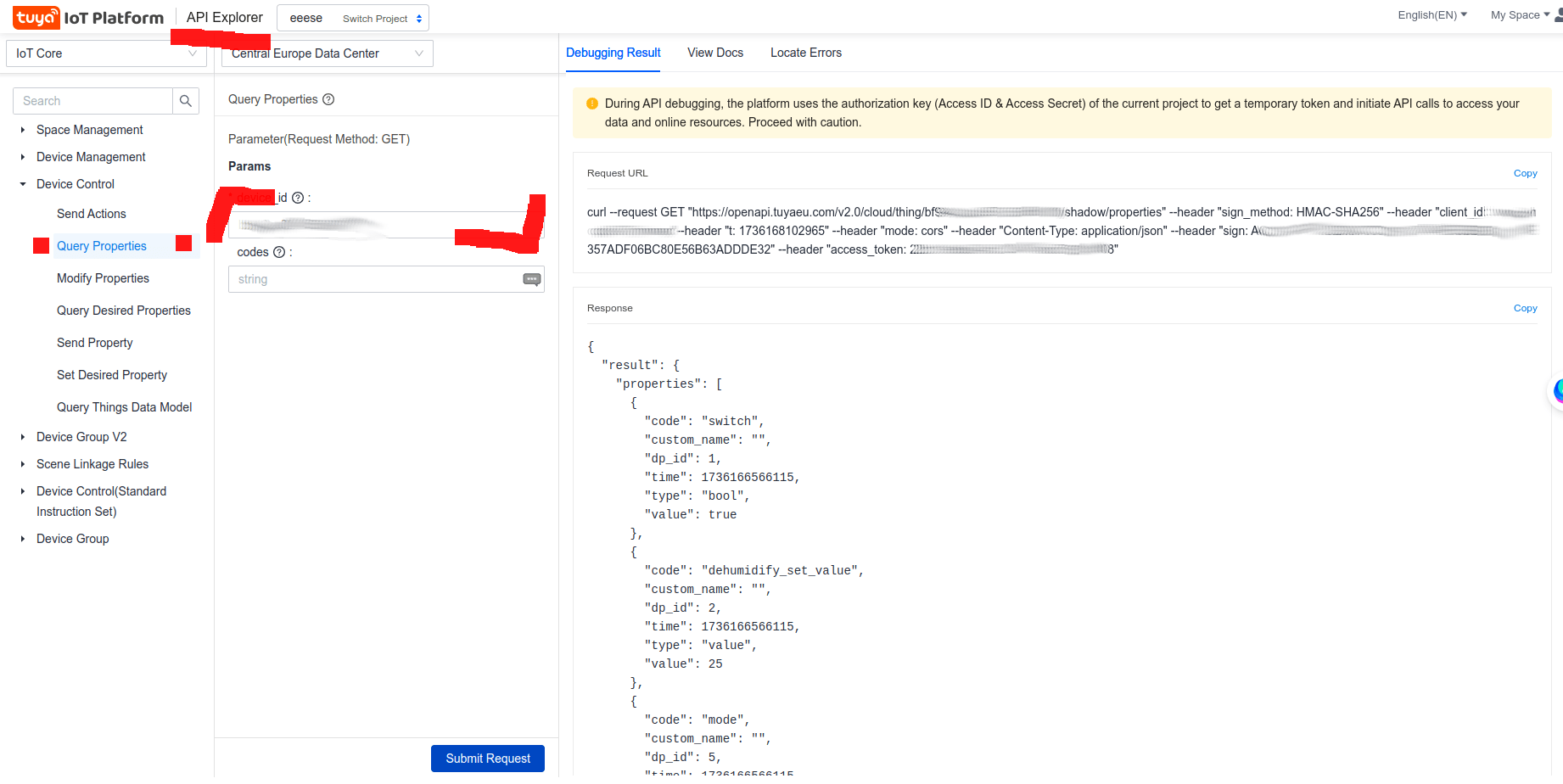
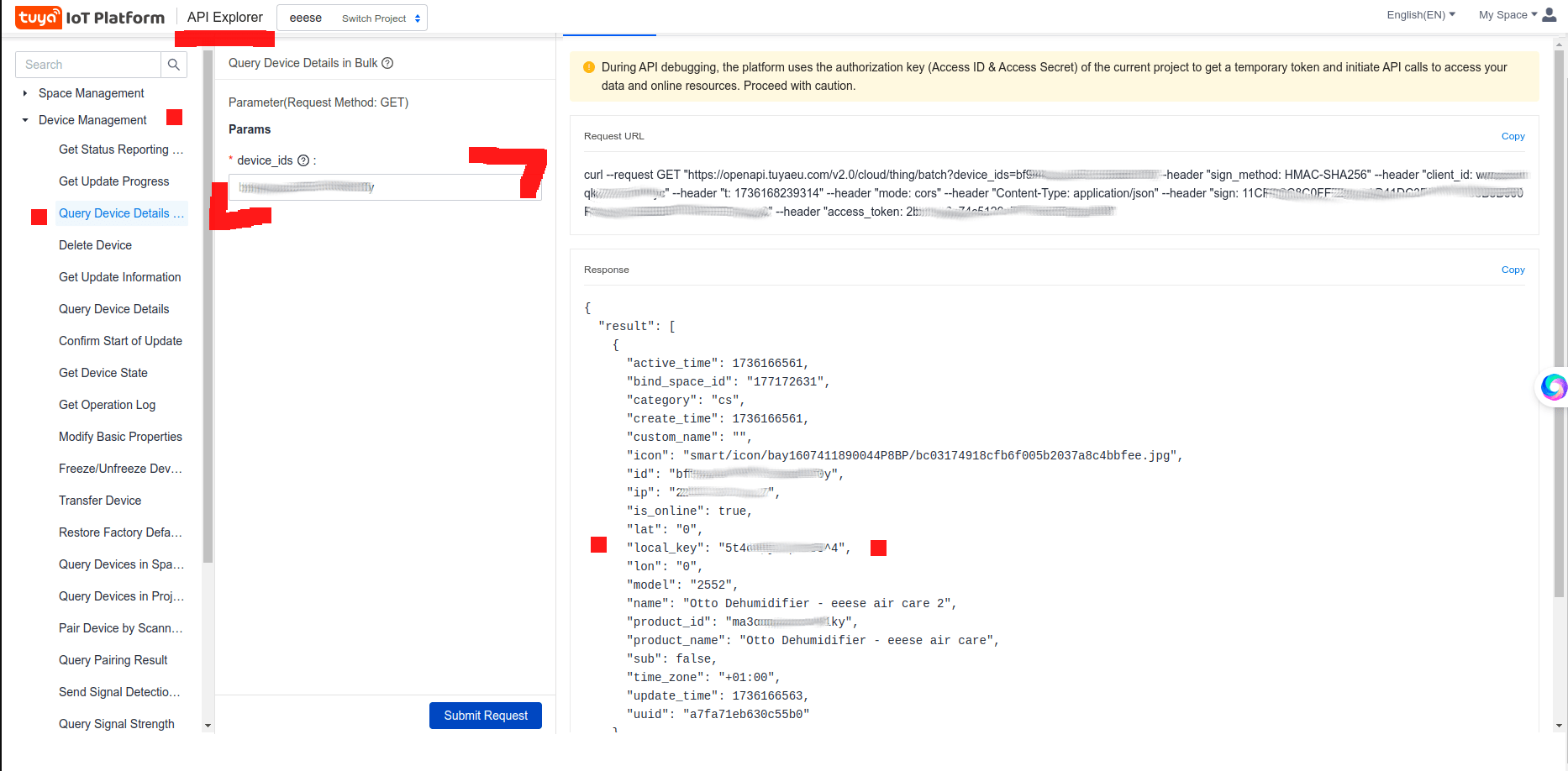
Gallery of config steps
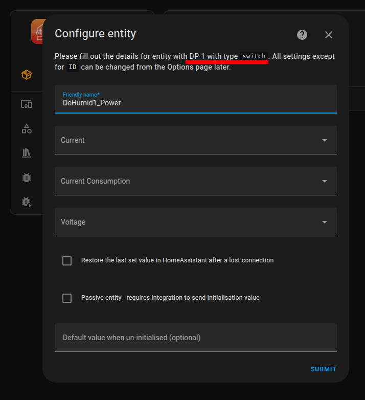
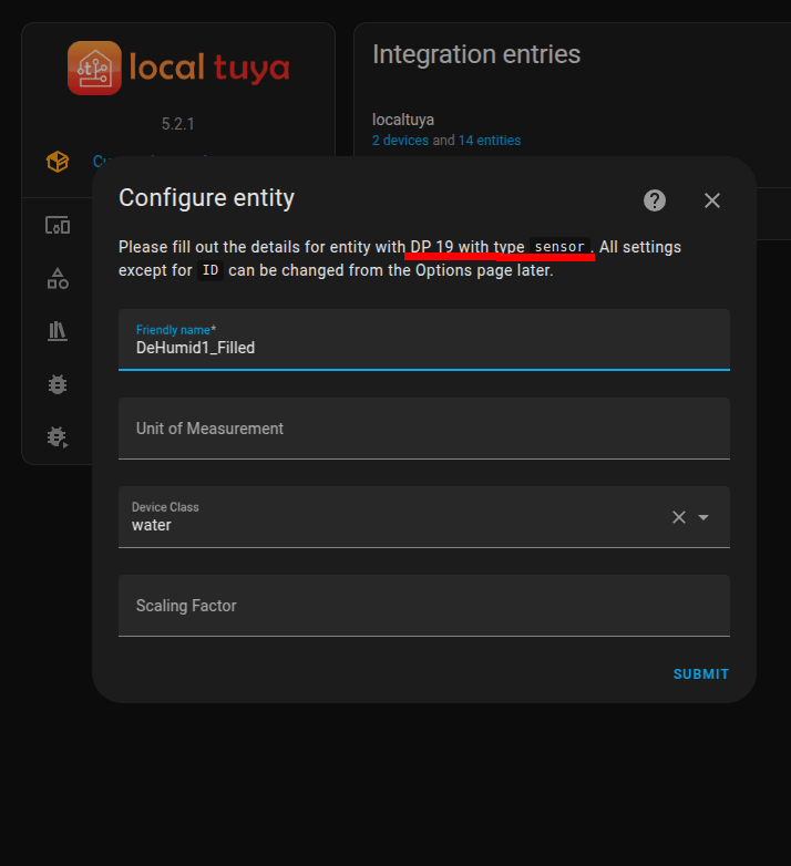
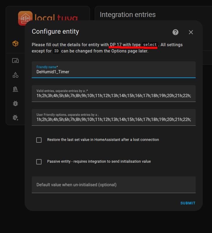

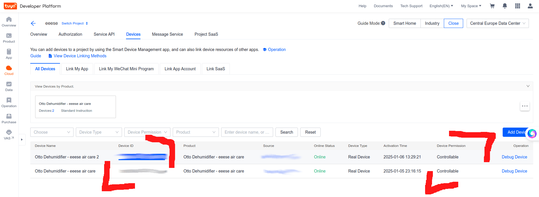
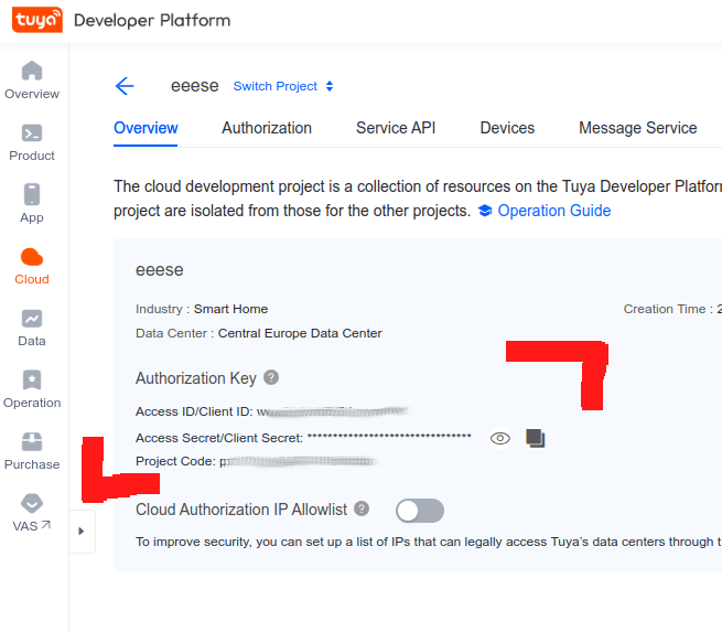
Developer website information, where to find your credentials.
(And a list of entities)
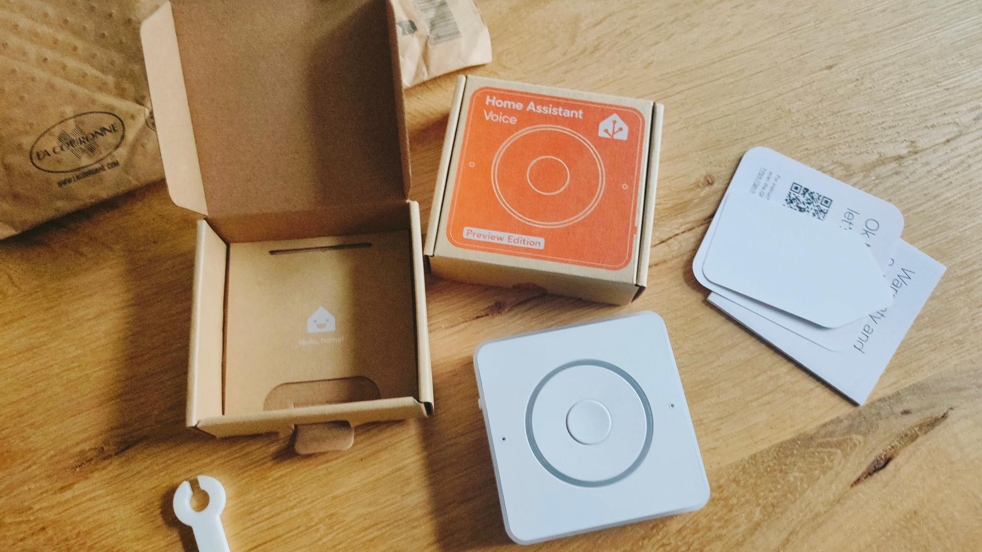
Yesterday I got my Home Assistant Voice!
This is a Non-Cloud solution like Alexa and Google devices.
I only could play with it for a few minutes because I was working on Arduino code with an ILI9341 Display and a BME280 (Temperature/Humidity/Air pressure).
Today I got some new goodies in, one of these is a LilyGO LoRa display which works on 433 Mhz.
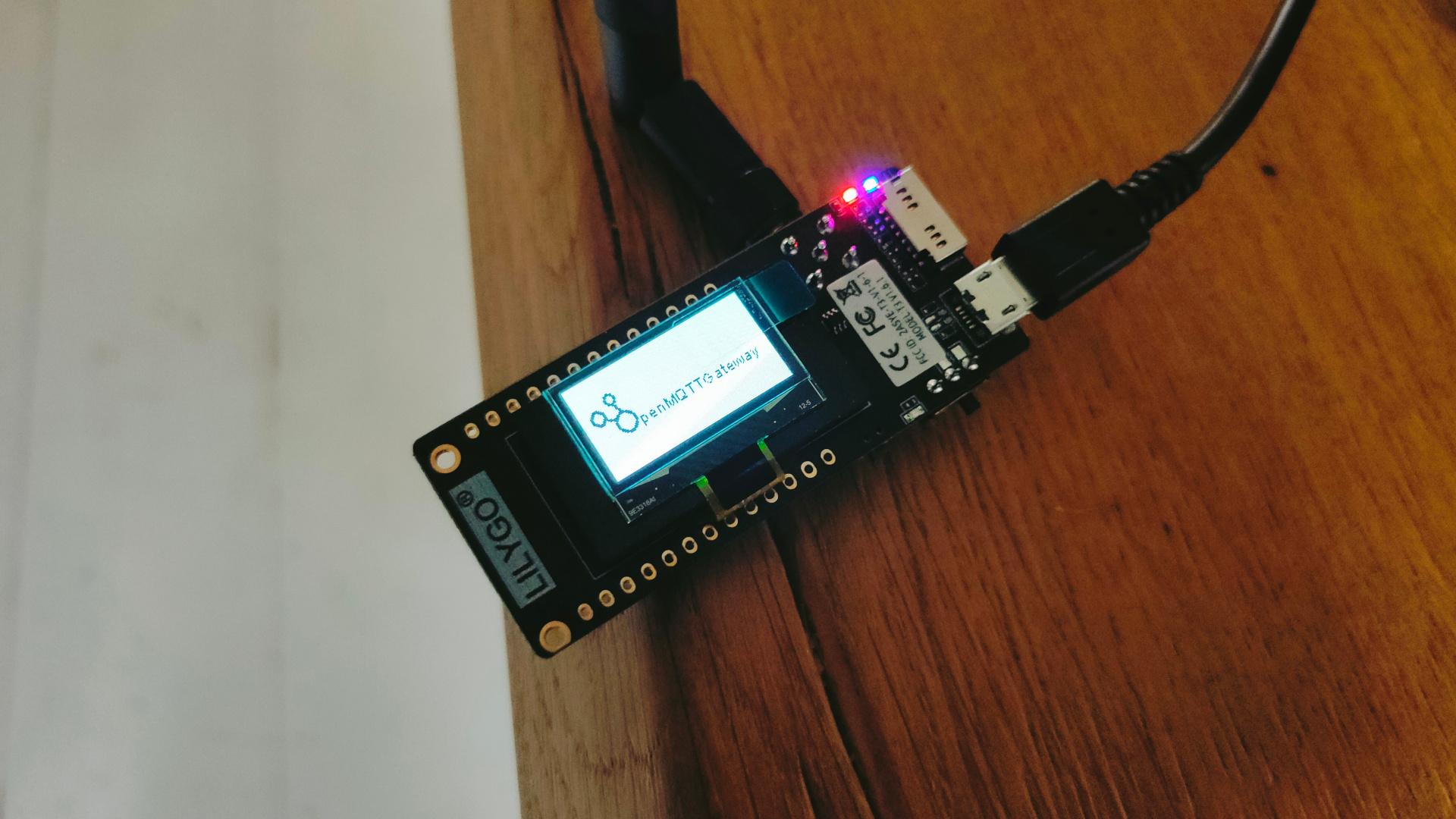
I flashed OpenMQTTGateway on this device.
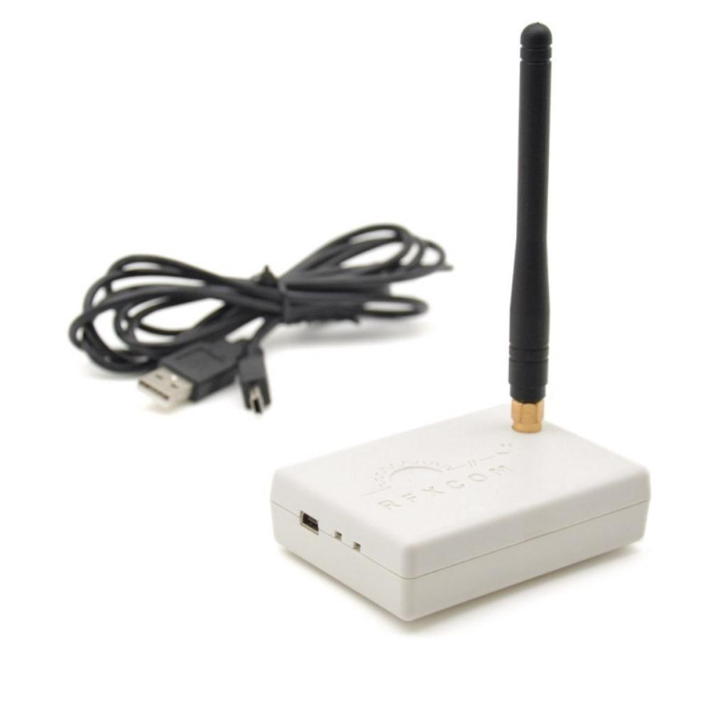
In the past, I posted about the RFCOM Gateway using Domoticz.
This runs on a Raspberry Pi.
While looking for alternatives, I found a rtl-sdr solution.
https://github.com/merbanan/rtl_433
Using this:
But I liked the ESP32 solution more.
Now I can dismantle Domoticz, which served me well for many years.
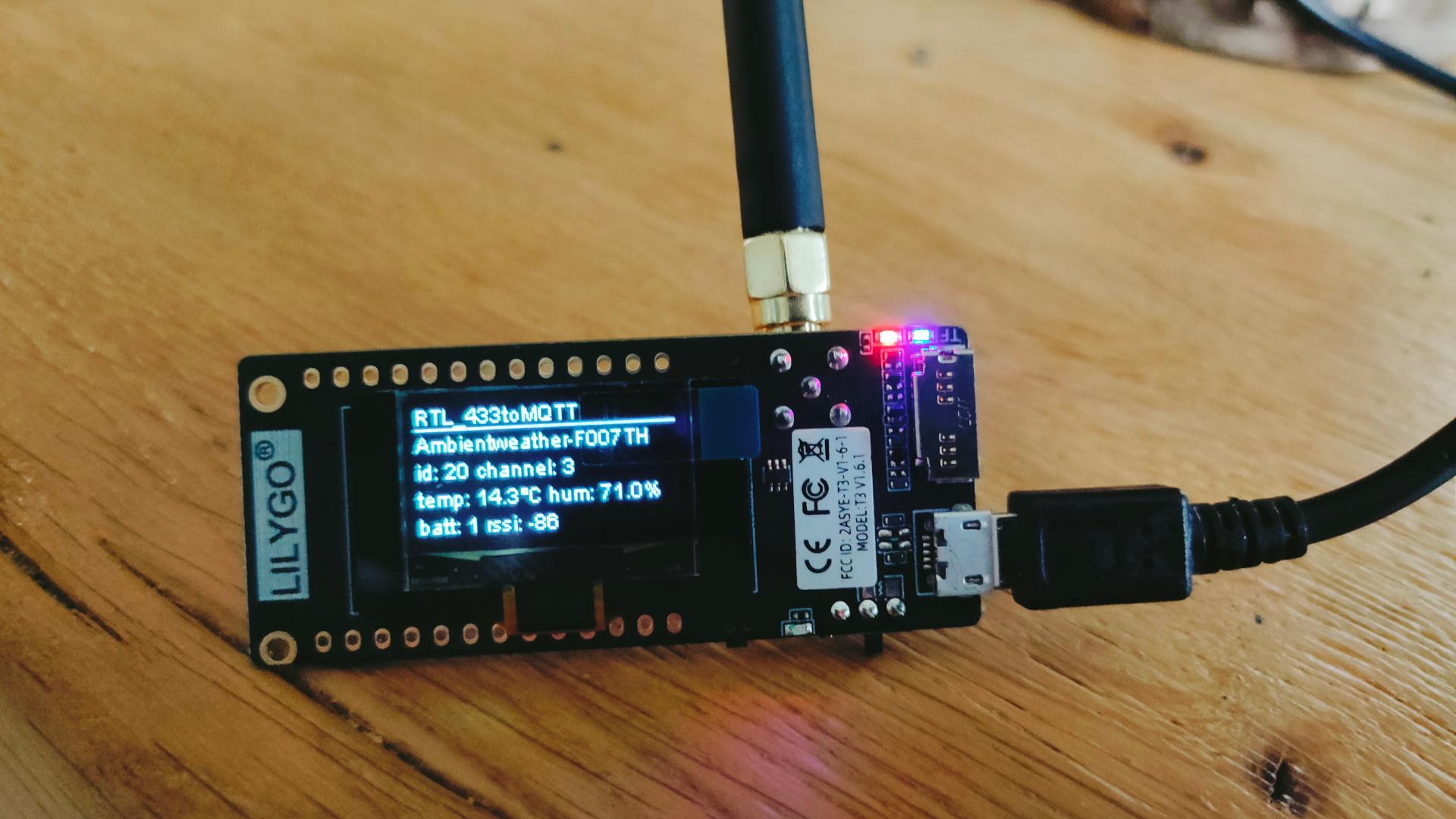
Note: This is a receiver device only!
But I only use read-only sensors like : Door/window, doorbell, temperature/humidity and Firesensors.
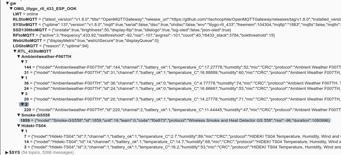
These are automatically detected in Home Assistant.
No more RFXCOM with a Raspberry.
While working on a client project, I tested multiple displays.
I thought it was fun to connect the Epaper to ESPHome.
It was not without problems. For example, the ESPHome editor gave squiggly lines under type.
This has to be changed in the libraries.
(Already notified developers)
model: 4.20in-V2 does not work .. use model: 4.20in-v2
esphome:
  name: epaperqoute
  friendly_name: epaperqoute

esp32:
  board: esp32dev
  framework:
    type: arduino

# Enable logging
logger:

# Enable Home Assistant API
api:
  encryption:
    key: "tzRSzZky3Jk+hUYtiybzT90kxxxxxxxxxxxxxxxxxxxxx="

ota:
  - platform: esphome
    password: "4f127e114a7a44fxxxxxxxxxxxxxxxxxxxxx"

wifi:
  ssid: !secret wifi_ssid
  password: !secret wifi_password

  # Enable fallback hotspot (captive portal) in case wifi connection fails
  ap:
    ssid: "Epaperqoute Fallback Hotspot"
    password: "yLSoxxxxxxxxxx"

captive_portal:


external_components:
  - source: github://pr#6209
    components: [ waveshare_epaper ]

text_sensor:
  - platform: homeassistant
    entity_id: input_text.epaper_display_text
    id: epaper_display_text
    on_value:
      then:
        - component.update: epaperdisplay

spi:
  clk_pin: GPIO13
  mosi_pin: GPIO14

# Upload own ttf to a directory in esphome/fonts using file editor in Home Assistant
font:
  - file: "fonts/newspaper.ttf"
    id: tahoma
    size: 64

http_request:
  verify_ssl: false

# image test
online_image:
  - url: "https://www.henriaanstoot.nl/epapertest.png"
    id: example_image
    format: PNG

#it.image(0, 0, id(example_image));

display:
  - platform: waveshare_epaper
    id: epaperdisplay
    cs_pin: GPIO15
    dc_pin: GPIO27
    busy_pin: GPIO25
    reset_pin: GPIO26
    model: 4.20in-v2
    reset_duration: 200ms
    update_interval: never
    lambda: |
           it.printf(0, 0, id(tahoma), "%s", id(epaper_display_text).state.c_str());
Part of a client’s build for powerful DC motors, so no details
Controlling this with an Arduino is straightforward, except for the SV signal.
This controls the speed using a voltage level.
A Uno has analog inputs, no outputs.
The trick is using a digital potmeter.
256 steps potmeter MCP41100
#include <SPI.h>
int svpin = 5;
setup:
  pinMode(svpin, OUTPUT);

loop:
// SPI Digital potmeter
  digitalPotWrite(0x20);
Running into some Ubuntu machines with keyboard mouse problems after upgrading to 24.04
fix:
apt get install xserver-xorg-input-synaptics
apt get install xserver-xorg-input-all
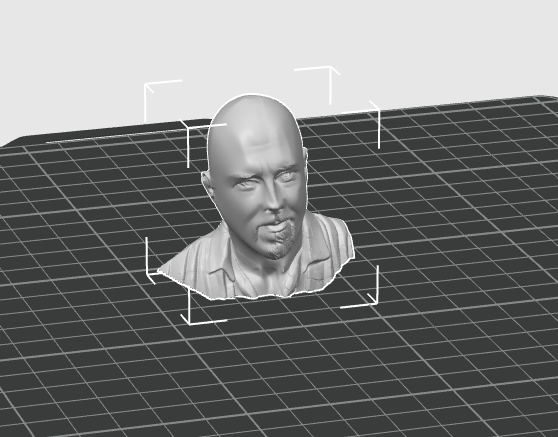
3D printing some test models generated with AI from a photo to make some boardgame pieces.
Meanwhile, I am testing big motor controllers for a new client.
Last week I was at a friend’s place, time to make a launcher creator in bash
#!/bin/bash
#
if [ $# -lt 2 ]; then
	echo "createlauncher.sh name (path/bin) path/name"
    exit 1
fi


cat << EOF > /tmp/$1
[Desktop Entry]
Type=Application
Terminal=false
Name=$1
Icon=~/bin/icon/$1.png
Exec=$2 $3
EOF

cp /tmp/$1  ~/.local/share/applications/$1.desktop
update-desktop-database
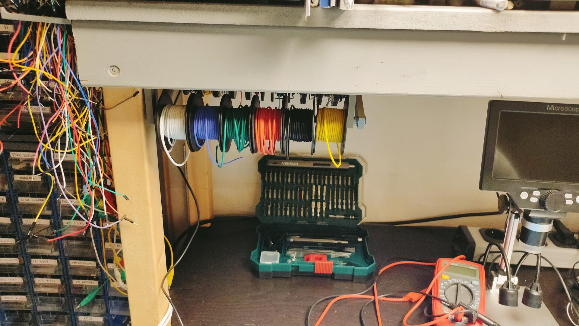
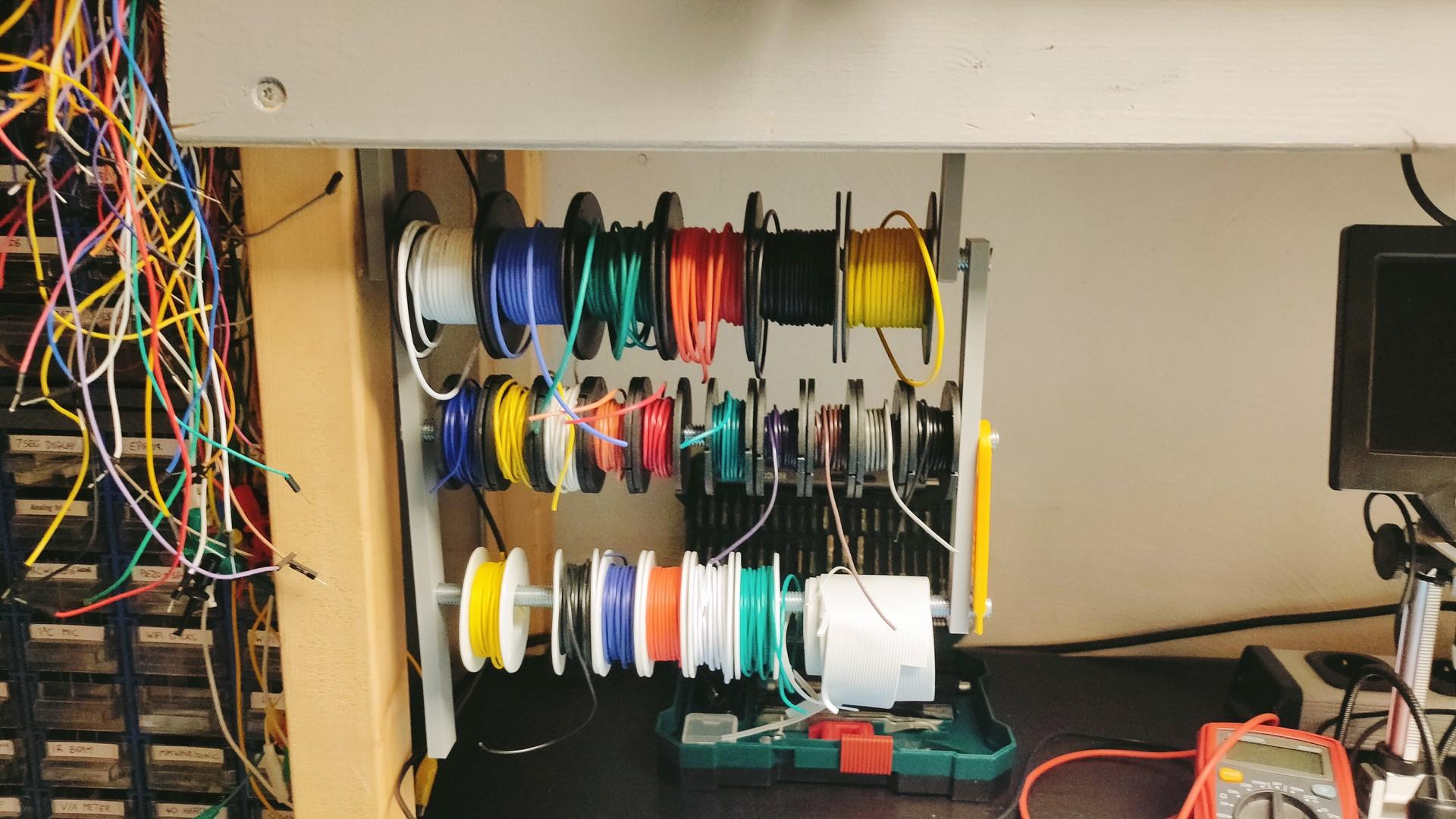
Made a cable holder in my lab (Already modded)
Can be folded upwards.
Did a lot of work in my new lab/workshop.
Got some cool new tools in. Post later
Also working on a new arrangement for a bagpipe tune.
Controlling windscreen wipers with Arduino for animatronics.
I was looking for a cheap solution to control movement, for example Halloween puppets.
I used a XY-160D dual 7A high amperage 12V controller to control a windscreen wiper.
Using a Arduino Uno and some simple code, I got movement out of the 12V motor.
Pins used:
Vcc – Arduino 5V
GND – Arduino GND
ENA – Arduino PWM pin
IN1 & IN2 (controls direction) – Two arduino output pins