Follow up on yesterday’s post
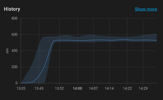
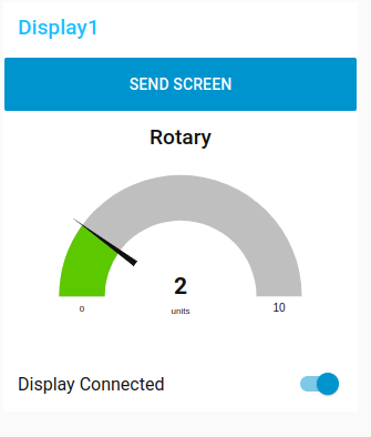
Using a html page with javascript, I made a proof of concept displaying realtime information from the sensor.
The sensor is active using a Home Assistant integration.
https://www.henriaanstoot.nl/2022/11/07/home-assistant-nodered-update/
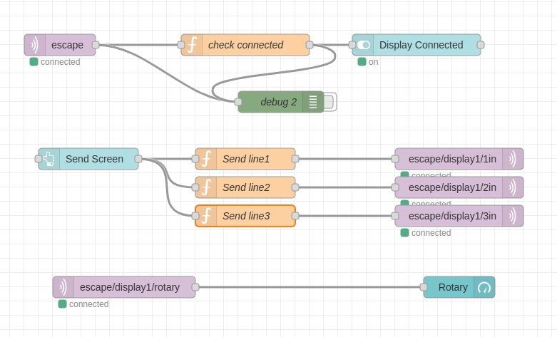
But using the Node-red integration, i take the payload and write this to a mqtt topic
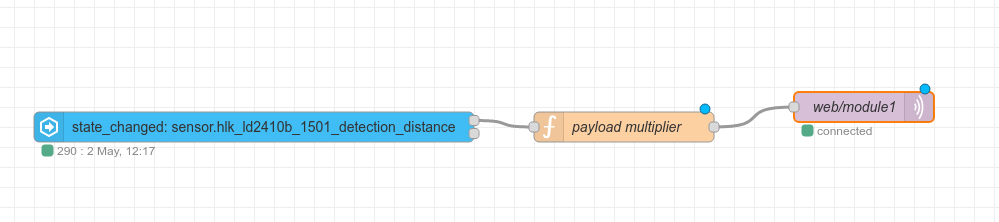
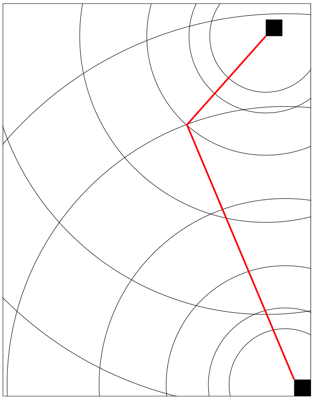
The HTML page below reads the topic using the websocket configured in mosquitto and draws the distance using canvas
cat /etc/mosquitto/conf.d/websockets.conf
listener 9001
protocol websockets
allow_anonymous true
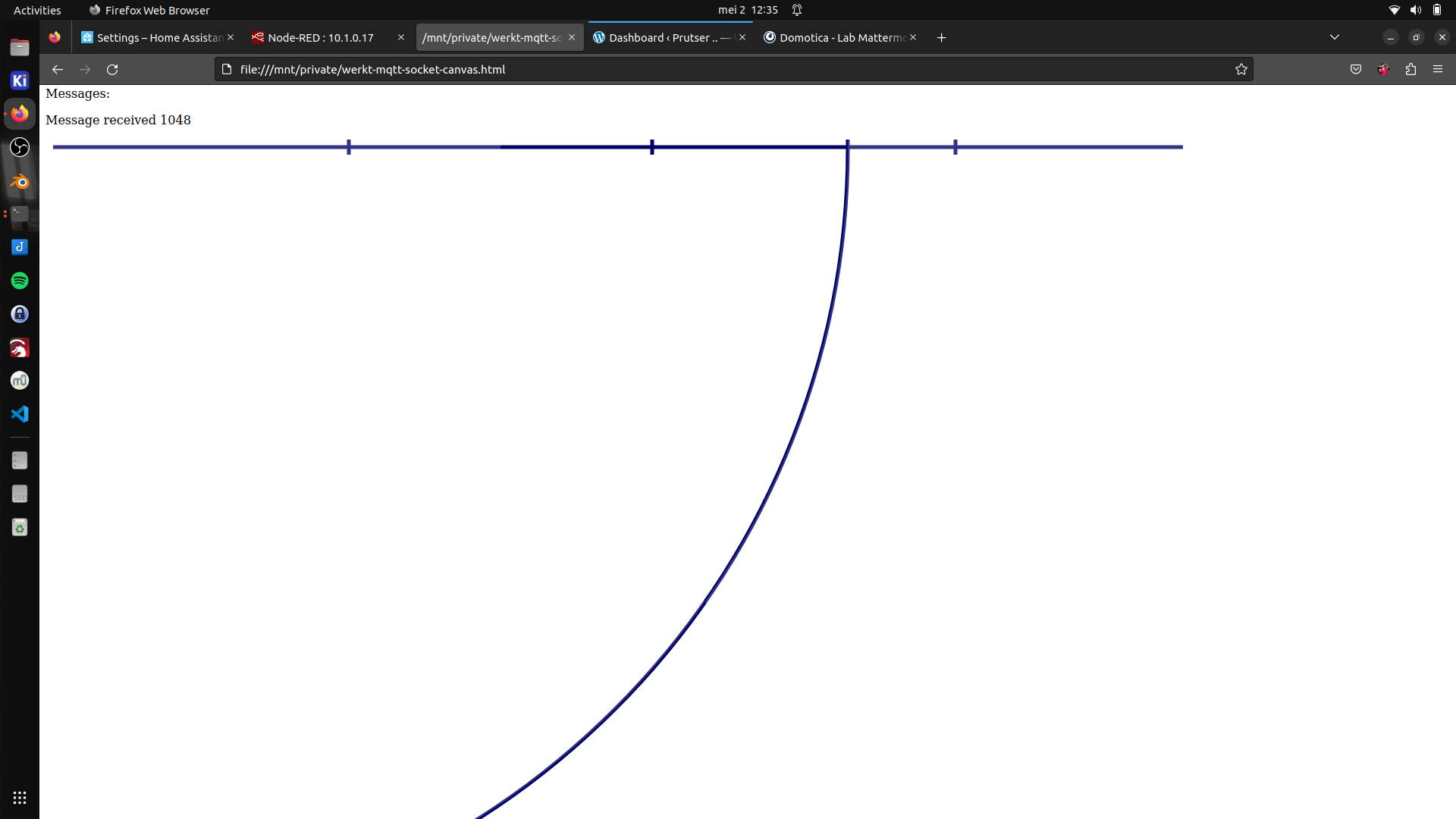
Distance drawn using canvas. Little dividers on top are meters
HTML PAGE with javascript
<?xml version="1.0" encoding="UTF-8" standalone="no"?>
<!DOCTYPE html PUBLIC "-//W3C//DTD XHTML 1.0 Transitional//EN" "http://www.w3.org/TR/xhtml1/DTD/xhtml1-transitional.dtd">
<html xmlns="http://www.w3.org/1999/xhtml">
  <head>
    <title></title>
    <meta name="viewport" content="width=device-width, initial-scale=1.0">
	<script src="https://cdnjs.cloudflare.com/ajax/libs/paho-mqtt/1.0.1/mqttws31.js" type="text/javascript"></script>
 	<script type = "text/javascript"
         src = "https://ajax.googleapis.com/ajax/libs/jquery/2.1.3/jquery.min.js"></script>
    <script type = "text/javascript">
	var connected_flag=0
	var mqtt;
    var reconnectTimeout = 2000;
	var host="MQTTSERVER";
	var port=9001;
var sub_topic="web/#";
	function onConnectionLost(){
	console.log("connection lost");
	document.getElementById("status").innerHTML = "Connection Lost";
	document.getElementById("messages").innerHTML ="Connection Lost";
	connected_flag=0;
	}
	function onFailure(message) {
		console.log("Failed");
		document.getElementById("messages").innerHTML = "Connection Failed- Retrying";
        setTimeout(MQTTconnect, reconnectTimeout);
        }
	function onMessageArrived(r_message){
		out_msg="Message received "+r_message.payloadString+"<br>";
		//out_msg=out_msg+"Message received Topic "+r_message.destinationName;
		//console.log("Message received ",r_message.payloadString);
		console.log(out_msg);
		document.getElementById("messages").innerHTML =out_msg;
		var topic=r_message.destinationName;
		if(topic=="web/module1")
		{
		document.getElementById("module1").innerHTML =r_message.payloadString;
		}
		if(topic=="web/module2")
		{
		document.getElementById("module2").innerHTML =r_message.payloadString;

		var canvas = document.getElementById('canvas');
var context = canvas.getContext('2d');
var centerX = 10;
context.clearRect(0, 0, 1800, 1000);
var centerY = 10;
var radius = r_message.payloadString;

let circle = new Path2D();  //
circle.arc(centerX, centerY, radius, 0, 2 * Math.PI, false);

//context.fillStyle = 'white';

context.fillStyle = "rgba(255, 255, 255, 0.2)";
context.fill(circle); //

context.lineWidth = 5;
context.strokeStyle = '#000066';
context.stroke(circle);  //

// top line
context.beginPath();
context.moveTo(10, 10);
context.lineTo(1500, 10);
context.stroke();

// 3x dividers
context.beginPath();
context.moveTo(400, 0);
context.lineTo(400, 20);
context.stroke();

context.beginPath();
context.moveTo(800, 0);
context.lineTo(800, 20);
context.stroke();

context.beginPath();
context.moveTo(1200, 0);
context.lineTo(1200, 20);
context.stroke();

		}
		}
	function onConnected(recon,url){
	console.log(" in onConnected " +reconn);
	}
	function onConnect() {
	  // Once a connection has been made, make a subscription and send a message.
	document.getElementById("messages").innerHTML ="Connected to "+host +"on port "+port;
	connected_flag=1
	document.getElementById("status").innerHTML = "Connected";
	console.log("on Connect "+connected_flag);
	mqtt.subscribe(sub_topic);
	  }

    function MQTTconnect() {

	console.log("connecting to "+ host +" "+ port);
	var x=Math.floor(Math.random() * 10000);
	var cname="controlform-"+x;
	mqtt = new Paho.MQTT.Client(host,port,cname);
	//document.write("connecting to "+ host);
	var options = {
        timeout: 3,
		onSuccess: onConnect,
		onFailure: onFailure,

     };

        mqtt.onConnectionLost = onConnectionLost;
        mqtt.onMessageArrived = onMessageArrived;
		//mqtt.onConnected = onConnected;

	mqtt.connect(options);
	return false;


	}
	function sub_topics(){
		document.getElementById("messages").innerHTML ="";
		if (connected_flag==0){
		out_msg="<b>Not Connected so can't subscribe</b>"
		console.log(out_msg);
		document.getElementById("messages").innerHTML = out_msg;
		return false;
		}
	var stopic= document.forms["subs"]["Stopic"].value;
	console.log("Subscribing to topic ="+stopic);
	mqtt.subscribe(stopic);
	return false;
	}
	function send_message(msg,topic){
		if (connected_flag==0){
		out_msg="<b>Not Connected so can't send</b>"
		console.log(out_msg);
		document.getElementById("messages").innerHTML = out_msg;
		return false;
		}
		var value=msg.value;
		console.log("value= "+value);
		console.log("topic= "+topic);
		message = new Paho.MQTT.Message(value);
		message.destinationName = "web/"+topic;

		mqtt.send(message);
		return false;
	}


    </script>

  </head>
  <body onload="MQTTconnect()">


 <table>
<tr><td>Sensor1:<td><td  id="module1"><td><td >
<tr><td>Sensor2:</td><td  id="module2"><td></tr>

</table>
<div id="status">Connection Status: Not Connected</div>
</div>
<br>

Messages:<p id="messages"></p>
     <canvas id="canvas" width="1600" height="1000"></canvas>
  </body>
</html>