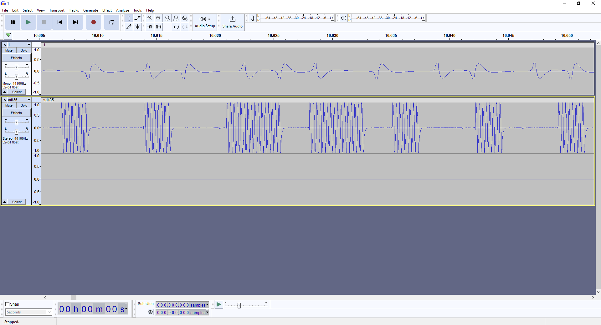
Here is Amazing Grace being played in reverse on a Bagpipe Practice Chanter. (I just looked at the Music Score and reverse played it, starting at the end.)
Why? Because I was bored.
Halfway the movie clip is the reversed reverse playing 🙂
The speech in reverse sounds like Serenissima, another tune we play with our Folkband.
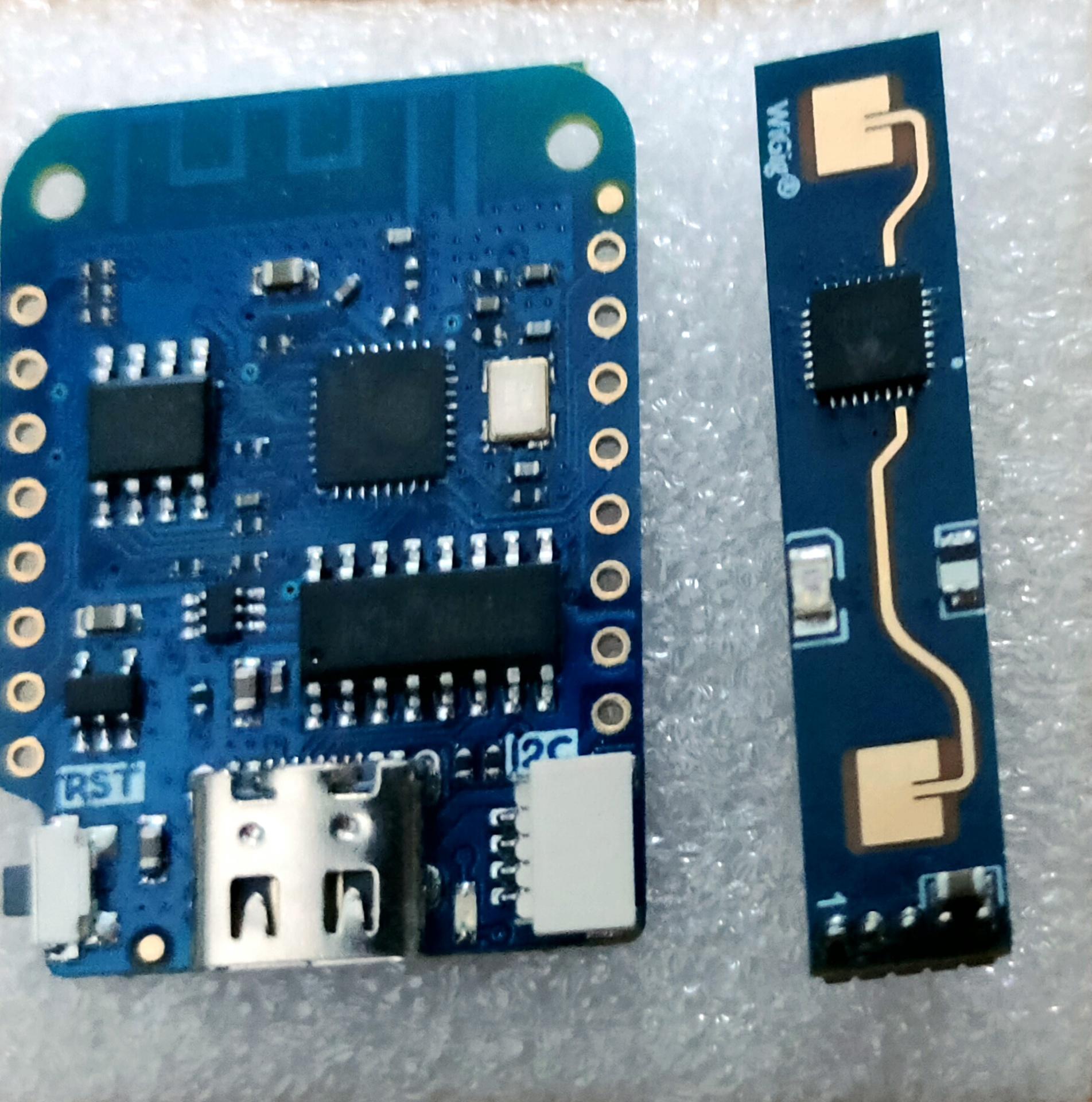
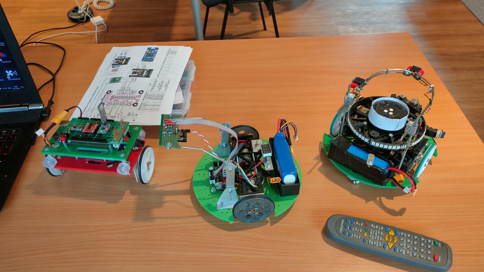
LD2410 is a high-sensitivity 24GHz human presence status sensing module developed by Hi-link. Its working principle is to use FMCW frequency-modulated continuous waves to detect human targets in the set space. Combined with radar signal processing and precise human body sensing algorithms, it realizes high-sensitivity human presence status sensing, and can identify human bodies in motion and stationary states. And auxiliary information such as the distance of the target can be calculated.
This product is mainly used in indoor scenes to sense whether there is a moving or micro-moving human body in the area, and output the detection results in real time. The farthest sensing distance can reach 5 meters, and the distance resolution is 0.75m. Provides a visual configuration tool, which can easily configure the sensing distance range, sensing sensitivity in different intervals and unmanned delay time, etc., to adapt to different specific application needs.
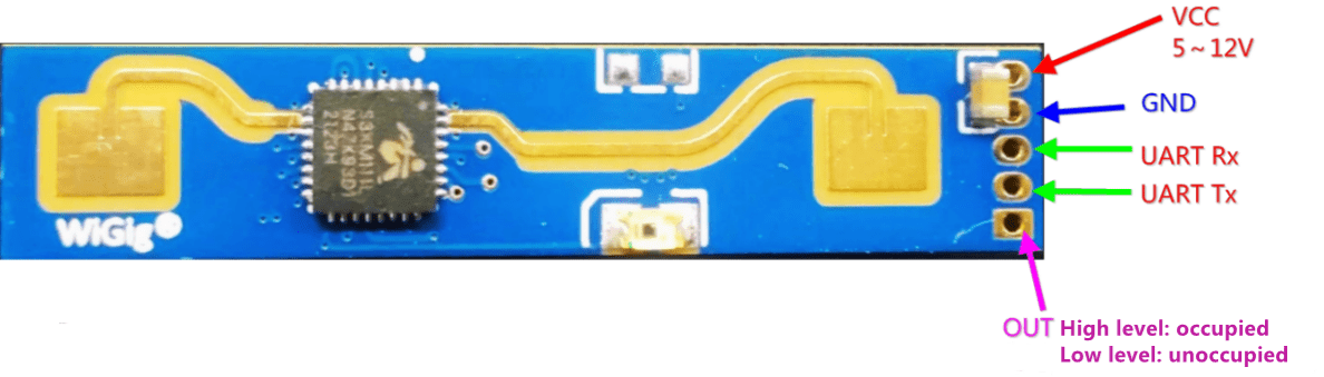
Support GPIO and UART output, plug and play, and can be flexibly applied to different smart scenarios and terminal products.
There are 3 versions: Without Bluetooth, with Bluetooth (B version) and a C version which uses the standard pin distance. The other ones are a pain in the *ss to solder!
Got a Bluetooth version? See end of post!
When searching for examples, I noticed that many had issues getting this working. Let me be clear, it wasn’t working for me the first time. Things i’ve learned:
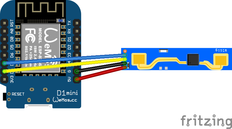
Flash the first initial ESPHome using a USB cable, after that you can connect the module and flash OTA
Do not use the standard Uart RX/TX, it didn’t work for me. And messes-up the logging over USB (See baudrate: 0 to turn this off)
When connecting D7/D8 and this signal gets pulled down, the wemos won’t boot. (Running wifi connections gets interrupted) This is also a sign that RX/TX is switched around!
Measure and make sure you have a good, stable 5V power to your LD2410
Here is a post about the RCWL-0516, a similar project, but this one can’t measure distances and person detection won’t work when a person is not moving.
Parts i’ve changed: board: Changed from esp-1?? to d1_mini logger: baud_rate: 0 tx_pin and rx_pin
esphome:
  name: ld2410-1
  friendly_name: ld2410-1

esp8266:
  board: d1_mini

# Enable logging
logger:
  baud_rate: 0

# Enable Home Assistant API
api:
  encryption:
    key: "xxxxxxxxxxxxxxxxxxxxxxxxxxxxxxxxxxxx="

ota:
  password: "xxxxxxxxxxxxxxxxxxxxxxxxxxxxxxxxxxxx"

wifi:
  ssid: !secret wifi_ssid
  password: !secret wifi_password

  # Enable fallback hotspot (captive portal) in case wifi connection fails
  ap:
    ssid: "Ld2410-1 Fallback Hotspot"
    password: "xxxxxxxxxxxxxxxxxxxxxxxxxxxxxxxxxxxx"

captive_portal:

ld2410:
  id: ld2410_radar

uart:
  tx_pin: GPIO15
  rx_pin: GPIO13
  baud_rate: 256000
  parity: NONE
  stop_bits: 1

number:
  - platform: ld2410
    timeout:
      name: Radar Timeout
    max_move_distance_gate:
      name: Radar Max Move Distance
    max_still_distance_gate:
      name: Radar Max Still Distance
    g0:
      move_threshold:
        name: g0 move threshold
      still_threshold:
        name: g0 still threshold
    g1:
      move_threshold:
        name: g1 move threshold
      still_threshold:
        name: g1 still threshold
    g2:
      move_threshold:
        name: g2 move threshold
      still_threshold:
        name: g2 still threshold
    g3:
      move_threshold:
        name: g3 move threshold
      still_threshold:
        name: g3 still threshold
    g4:
      move_threshold:
        name: g4 move threshold
      still_threshold:
        name: g4 still threshold
    g5:
      move_threshold:
        name: g5 move threshold
      still_threshold:
        name: g5 still threshold
    g6:
      move_threshold:
        name: g6 move threshold
      still_threshold:
        name: g6 still threshold
    g7:
      move_threshold:
        name: g7 move threshold
      still_threshold:
        name: g7 still threshold
    g8:
      move_threshold:
        name: g8 move threshold
      still_threshold:
        name: g8 still threshold

binary_sensor:
  - platform: ld2410
    has_target:
      name: Radar Target
      id: radar_has_target
    has_moving_target:
      name: Radar Moving Target
    has_still_target:
      name: Radar Still Target
button:
  - platform: ld2410
    factory_reset:
      name: "factory reset"
    restart:
      name: "restart"
    query_params:
      name: query params

sensor:
  - platform: ld2410
    moving_distance:
      name: Radar Moving Distance
      id: moving_distance
    still_distance:
      name: Radar Still Distance
      id: still_distance
    moving_energy:
      name: Radar Move Energy
    still_energy:
      name: Radar Still Energy
    detection_distance:
      name: Radar Detection Distance
      id: radar_detection_distance
    g0:
      move_energy:
        name: g0 move energy
      still_energy:
        name: g0 still energy
    g1:
      move_energy:
        name: g1 move energy
      still_energy:
        name: g1 still energy
    g2:
      move_energy:
        name: g2 move energy
      still_energy:
        name: g2 still energy
    g3:
      move_energy:
        name: g3 move energy
      still_energy:
        name: g3 still energy
    g4:
      move_energy:
        name: g4 move energy
      still_energy:
        name: g4 still energy
    g5:
      move_energy:
        name: g5 move energy
      still_energy:
        name: g5 still energy
    g6:
      move_energy:
        name: g6 move energy
      still_energy:
        name: g6 still energy
    g7:
      move_energy:
        name: g7 move energy
      still_energy:
        name: g7 still energy
    g8:
      move_energy:
        name: g8 move energy
      still_energy:
        name: g8 still energy
Bluetooth:
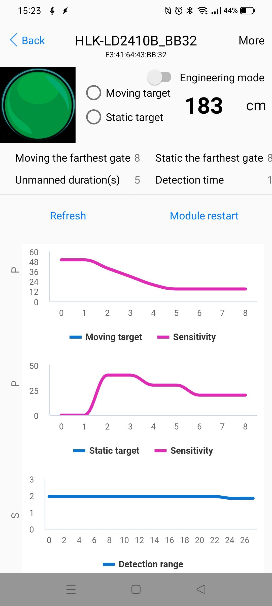
I’ve connected this HLK-DL2410B to Home Assistant before using Bluetooth. But I wanted to get them connected using Wifi.
You can install an App on your phone to connect to the sensor when powered on. This way you can test the device, but also upgrade the firmware and make adjustments!
Just enable engineering mode and click more.
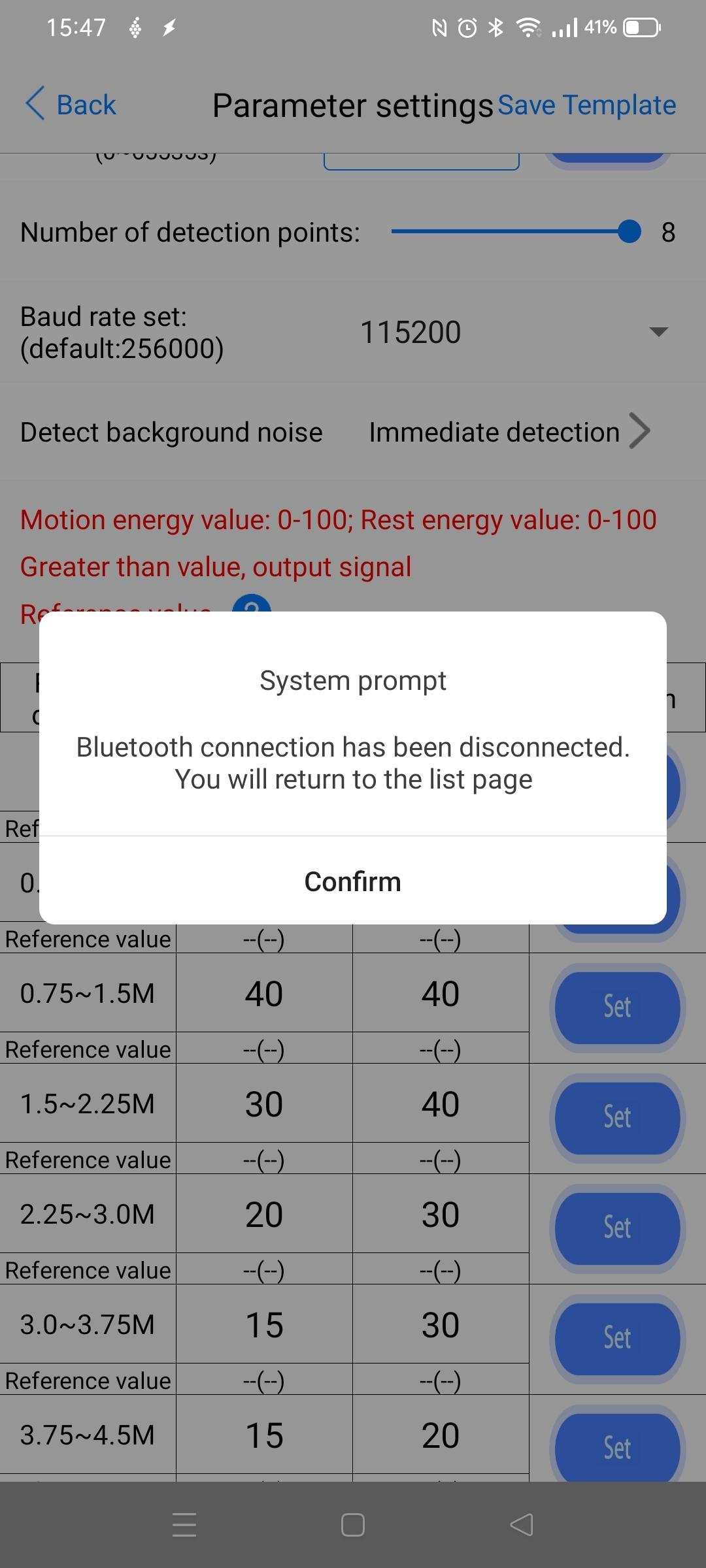
Testing another baud rate and upgrading the firmware:
Posted because I could not find a good example on the interwebs.
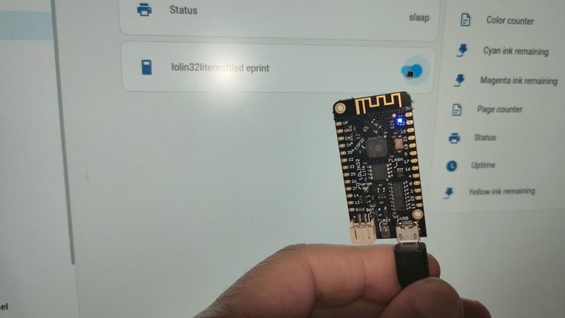
Below creates a virtual HA button which toggles a blinking led. (button and variables are called eprint for another function, change to something meaningful. )
Home Assistant virtual mqtt switch (configuration.yml)
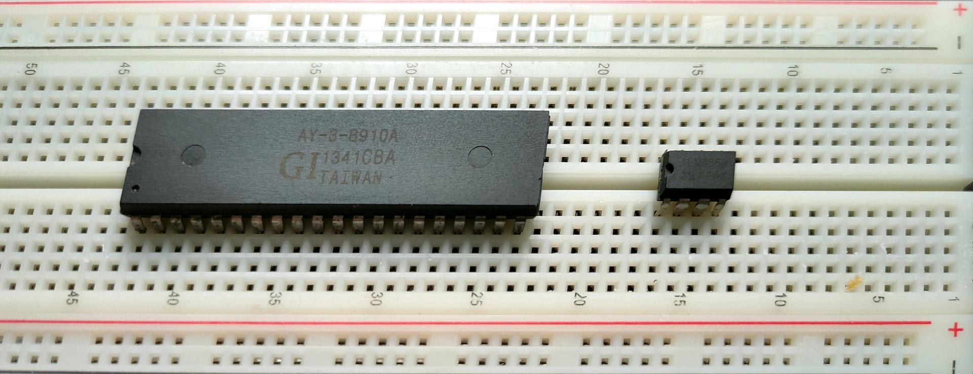
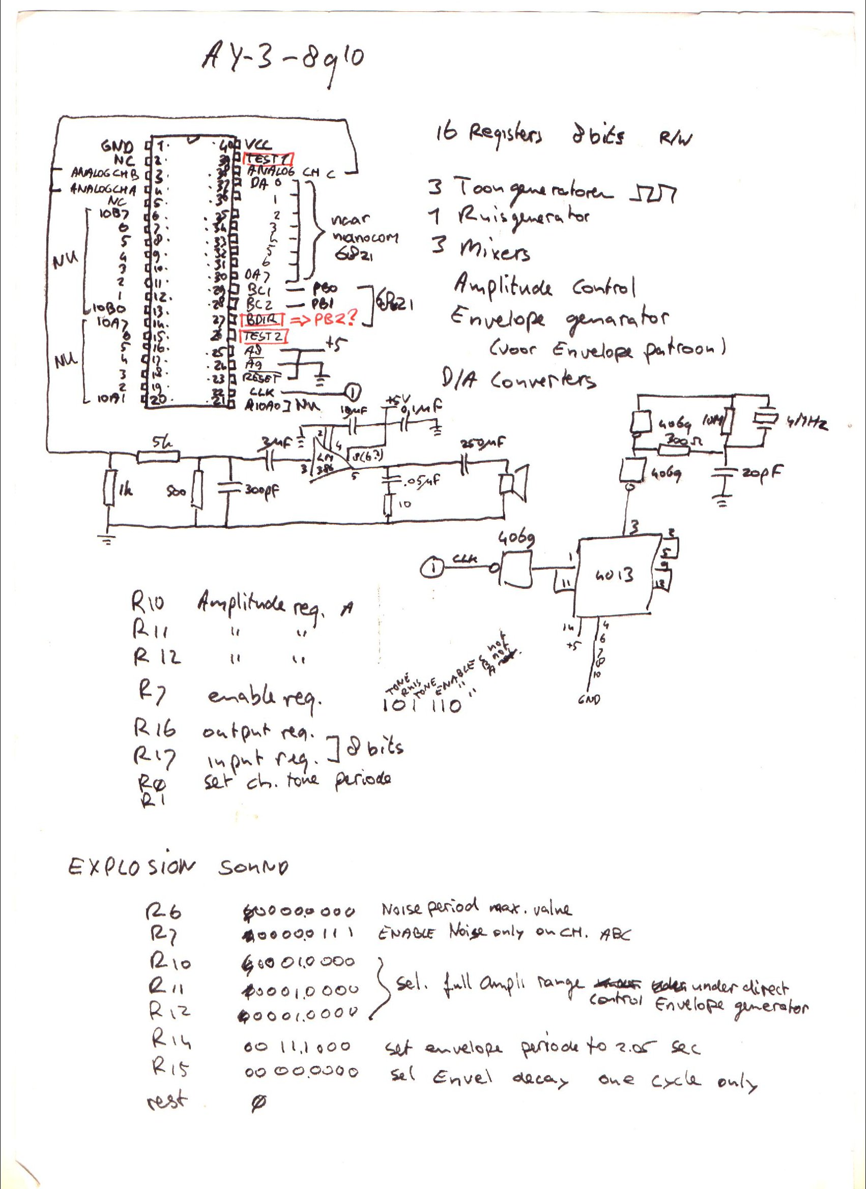
I’ve written about General Instrument AY-3-8910 before, here is some work I did today.
This sound chip i wanted to implement in my amiga, and now it’s a alternative for my 6502 computer. ( As an alternative setup for the SID chip. ) Btw this is the same kind of chip used in the Atari ST.
Above a Kicad drawing I made today, a little different from my design from the 90’s.
Below a movie clip I recorded today. Running a test setup using an Arduino nano and a sdcard reader. The sound is bad, this is due to clipping and the absence of multiple resistors and capacitors. Music is a register dump from a YM music file. Amplifier is a bare LM386.
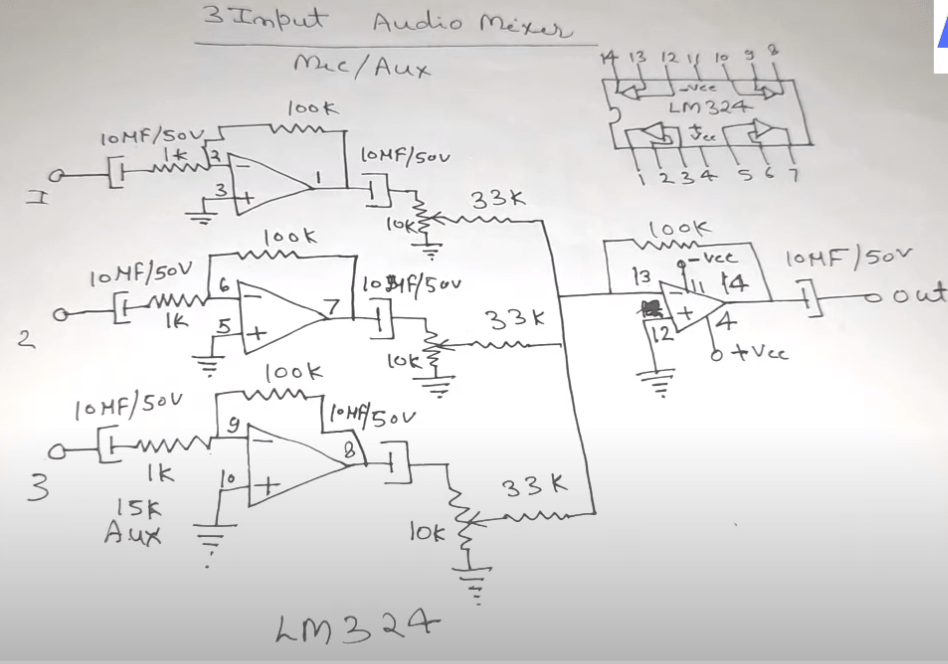
UPDATE: 20240225
I don’t like tying those three outputs together, and amplifying those.
So I’m going to use a LM324 i’ve got left from my 8085 interface, and make a 3-channel amplifier.
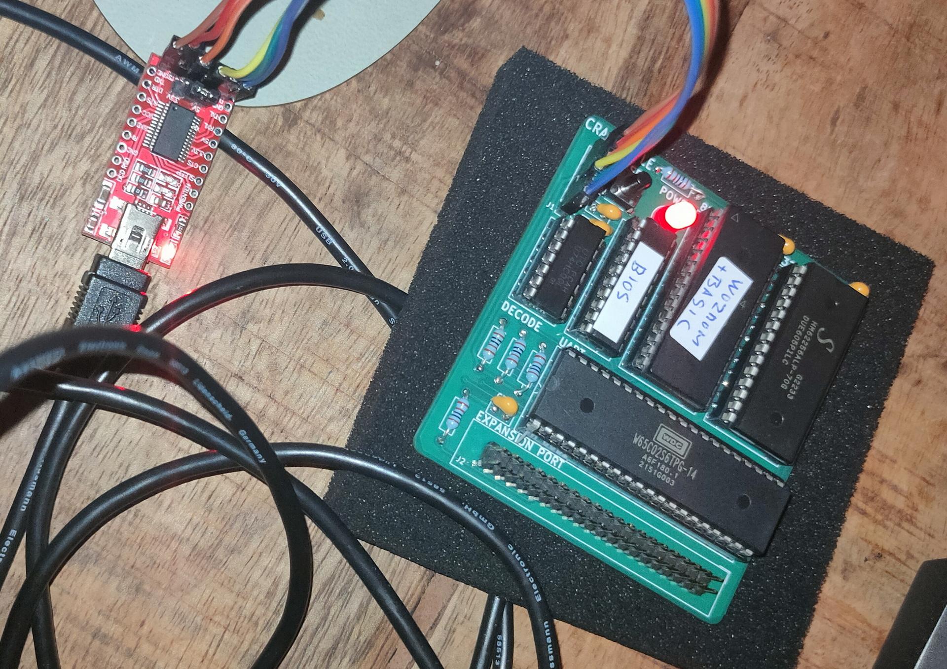
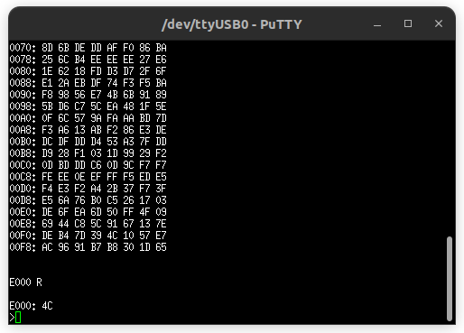
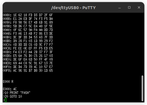
It has an EPROM with Wozmon and Basic for now. I have to redo the address decoder, but I like the simple serial interface by Geoffrey. (I hate the PIC18F15Q41, made by Microchip, but still the best minimal option .. for now)
Probably the last time i’ve used a pic was in 1998
I’ve posted in the past something about pl/m. Today i got this running again in a dosbox.
The PL/M programming language (an acronym of Programming Language for Microcomputers) is a high-level language conceived and developed by Gary Kildall in 1973 for Intel’s microprocessors.
PLM86 PROGRAM.PLM
LINK86 PROGRAM.OBJ, PLM\DOSLIBS.LIB, PLM\UTILS.LIB TO %1.LNK INITCODE
LINK PROGRAM.LNK;;;
Tic Tac Toe in PLM
bke:do;
/*DOEL:                                              */
/*Dit programma is boter kaas en eieren voor twee    */
/*spelers, er wordt gecontroleerd of iemand gewonnen */
/*heeft. (Je speelt niet tegen de computer)          */
/*UPDATE:12/2/90,15/2/90,18/2/90  RELDATE:19/2/90    */
/*PROGRAMMER:H.M.Aanstoot                            */
/*UPDATE 5/3/90 1:13:23                              */
/*De volgende 4 regels zorgen ervoor dat de compiler */
/*de PLM  DOS,UTIL routines die op disk staan        */
/*meestuurt naar de linker                           */
/* bla bla 2de versie met STRINGS!! eindelijk gelukt */

$include(plm\doslibs.inc)
$include(plm\doslibs.dcl)
$include(plm\utils.dcl)
dcl naam(3)           pointer;
dcl plaats(9)         word;
dcl teken(2)          pointer;
dcl aanzet            word;
dcl loop              word;
dcl a                 word;
dcl winnaar           word;
dcl nummer            word;
dcl item              word;
dcl error_status      word;

spelerzet:procedure;
call dsso(naam(aanzet));
call dsso(@(', geef een getal: $'));
invoer:
nummer=dsin;
nummer=nummer-48;
if nummer<1 or nummer>9 then goto invoer;
if plaats(nummer)<>0 then goto invoer;
call dso(nummer+48);
plaats(nummer)=aanzet;
end spelerzet;

update:procedure;
item=1;
call dsso(@(cr,lf,'+-----+-----+-----+',cr,lf,eos));
call dsso(@('|     |     |     |',cr,lf,eos));
call dso(124);call zet;call dso(124);call zet;call dso(124);call zet;
 call dsso(@(124,cr,lf,eos));
call dsso(@('|     |     |     |',cr,lf,eos));
call dsso(@('+-----+-----+-----+',cr,lf,eos));
call dsso(@('|     |     |     |',cr,lf,eos));
call dso(124);call zet;call dso(124);call zet;call dso(124);call zet;
 call dsso(@(124,cr,lf,eos));
call dsso(@('|     |     |     |',cr,lf,eos));
call dsso(@('+-----+-----+-----+',cr,lf,eos));
call dsso(@('|     |     |     |',cr,lf,eos));
call dso(124);call zet;call dso(124);call zet;call dso(124);call zet;
 call dsso(@(124,cr,lf,eos));
call dsso(@('|     |     |     |',cr,lf,eos));
call dsso(@('+-----+-----+-----+',cr,lf,eos));

  call dsso(@('    1   2   3',cr,lf,eos));
  call dsso(@('    4   5   6',cr,lf,eos));
  call dsso(@('    7   8   9',cr,lf,eos));
end update;


zet:procedure;
if plaats(item)=0 then call dsso(@('     $'));
if plaats(item)=1 then call dsso(@('  X  $'));
if plaats(item)=2 then call dsso(@('  O  $'));
item=item+1;
end zet;

check:procedure;
   do a=1 to 2;
   if plaats(1)=a and plaats(2)=a and plaats(3)=a then winnaar=a;
   if plaats(4)=a and plaats(5)=a and plaats(6)=a then winnaar=a;
   if plaats(7)=a and plaats(8)=a and plaats(9)=a then winnaar=a;

   if plaats(1)=a and plaats(4)=a and plaats(7)=a then winnaar=a;
   if plaats(2)=a and plaats(5)=a and plaats(8)=a then winnaar=a;
   if plaats(3)=a and plaats(6)=a and plaats(9)=a then winnaar=a;

   if plaats(1)=a and plaats(5)=a and plaats(9)=a then winnaar=a;
   if plaats(3)=a and plaats(5)=a and plaats(7)=a then winnaar=a;
   end;
end check;


hoofdprogramma:
winnaar=3;
naam(1)=@('Speler 1$');
naam(2)=@('Speler 2$');
naam(3)=@('Niemand$');
do a=1 to 9; plaats(a)=0; end;
teken(1)=@('kruisje$');
teken(2)=@('rondje$');
aanzet=1;

    do loop=1 to 9;
    call update;
    call check;
    if winnaar<>3 then goto gewonnen;
    call spelerzet;
    aanzet=3-aanzet;
    end;

call update;
gewonnen:
call dsso(naam(winnaar));
call dsso(@(' heeft gewonnen',cr,lf,eos));
if winnaar=3 then call dsso(@('Helaas, pindakaas!$'));
			 else call dsso(@('Gefeliciteerd ermee!$'));

call dexit(error_status);
end;
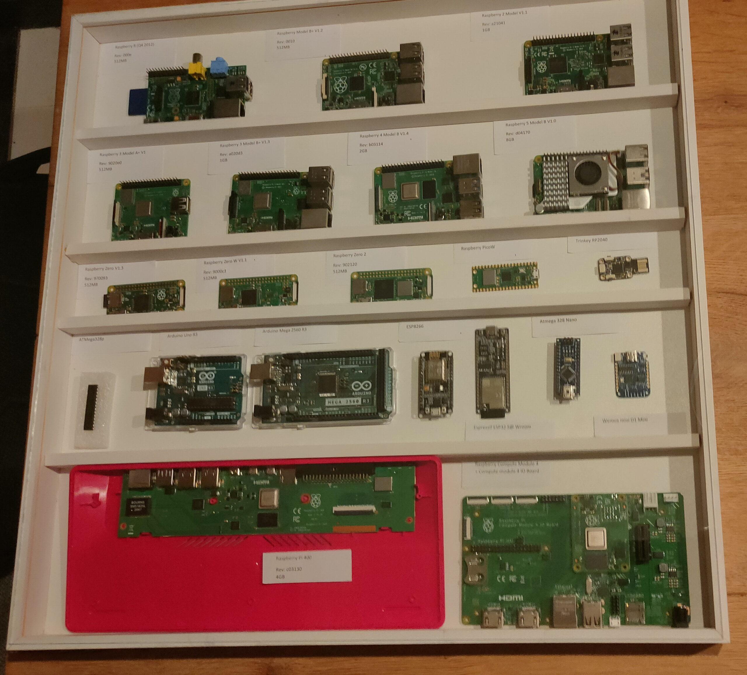
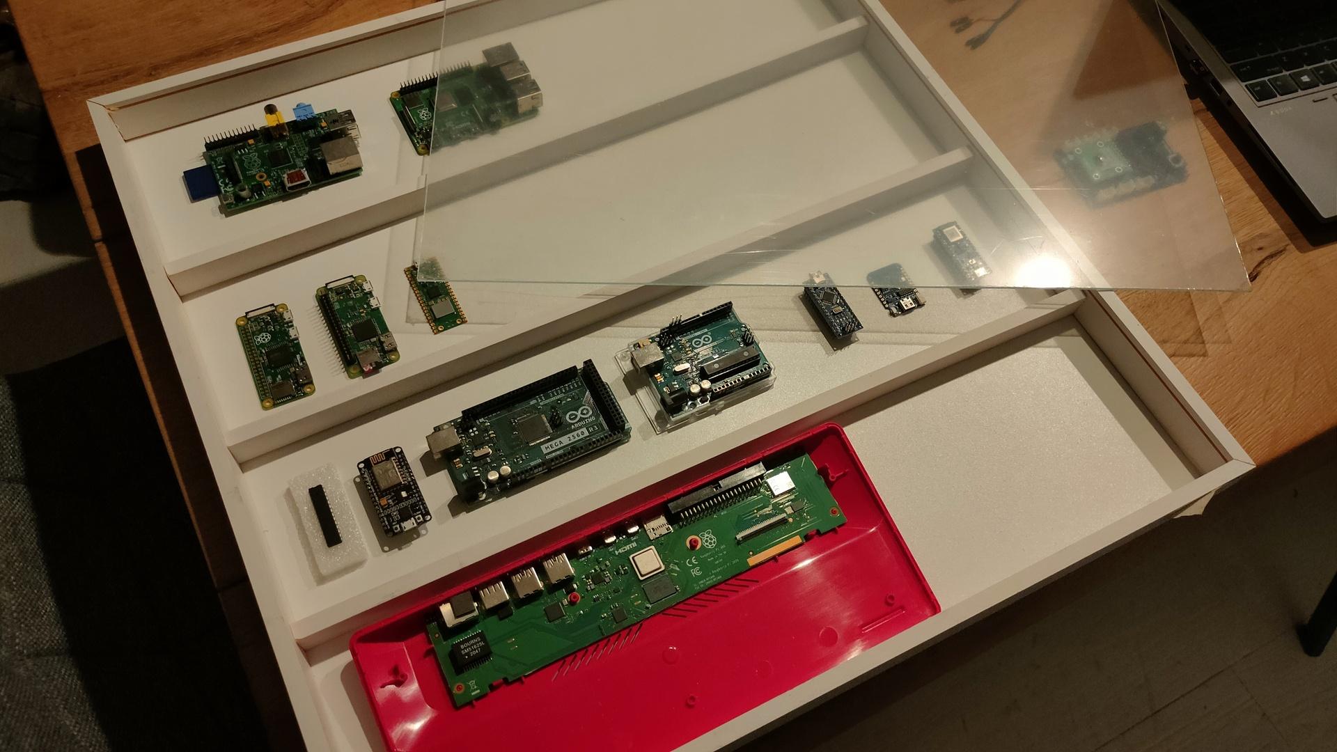
I started a little case for a collection of Raspberry devices.
Over the years, many Raspberries were designed and made. It all started in 2012 I want to have a case with all RP’s i’ve used.
There are many iterations of the RPi, I’m missing a lot now. If you want to help me, send me old/broken raspberries to get the collection complete!
This is the case at the moment
Case with some Raspberries and Arduino’s I found lying around, I’m not going to dismantle projects. Only the RPi 1A, 4B, Zero, Zero W, Pico and RPi 400 are displayed. Plastic sheet as protective layer still on there, should be clear as glass.
The case isn’t glued together yet. I’m not sure how and what to include.
Horizontal wooden bars to place the devices on?
Include a history of Arduino’s for now?
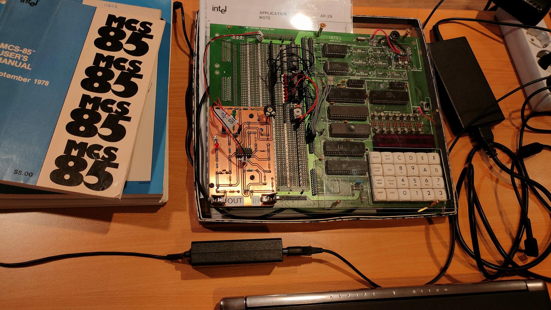
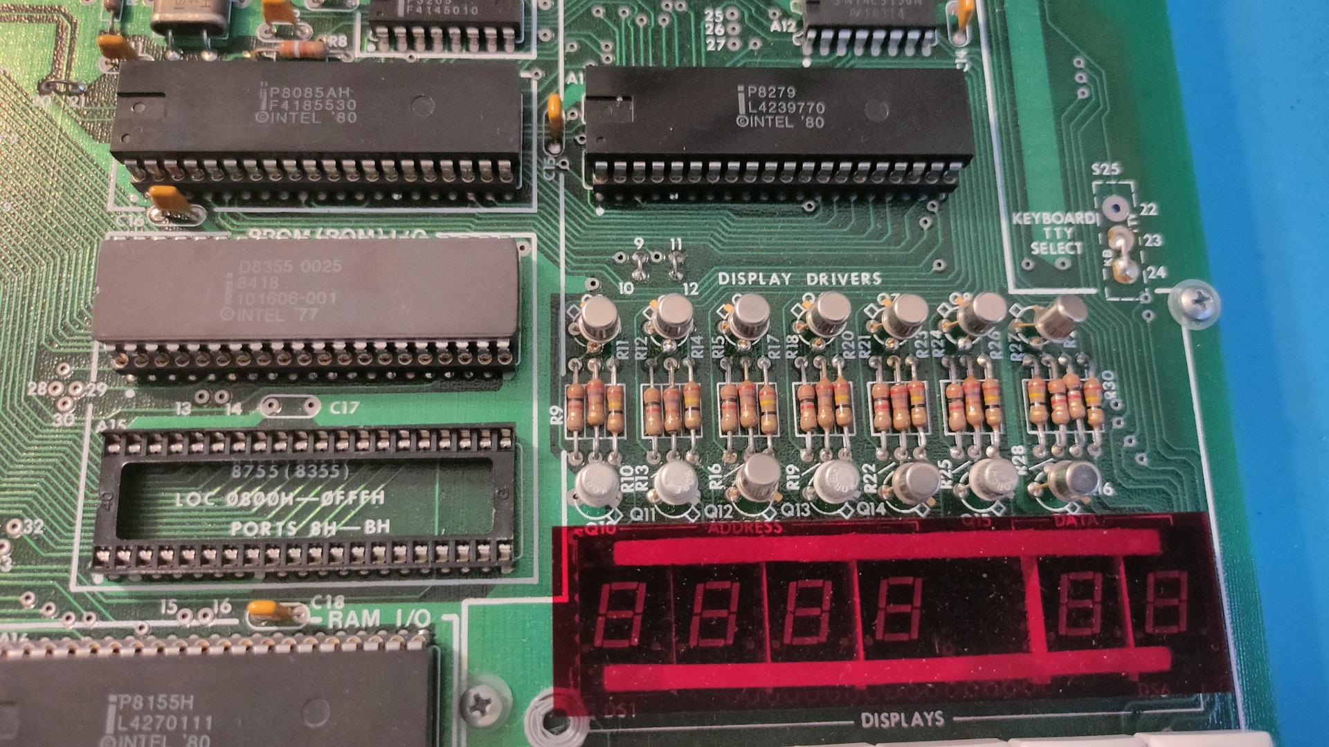
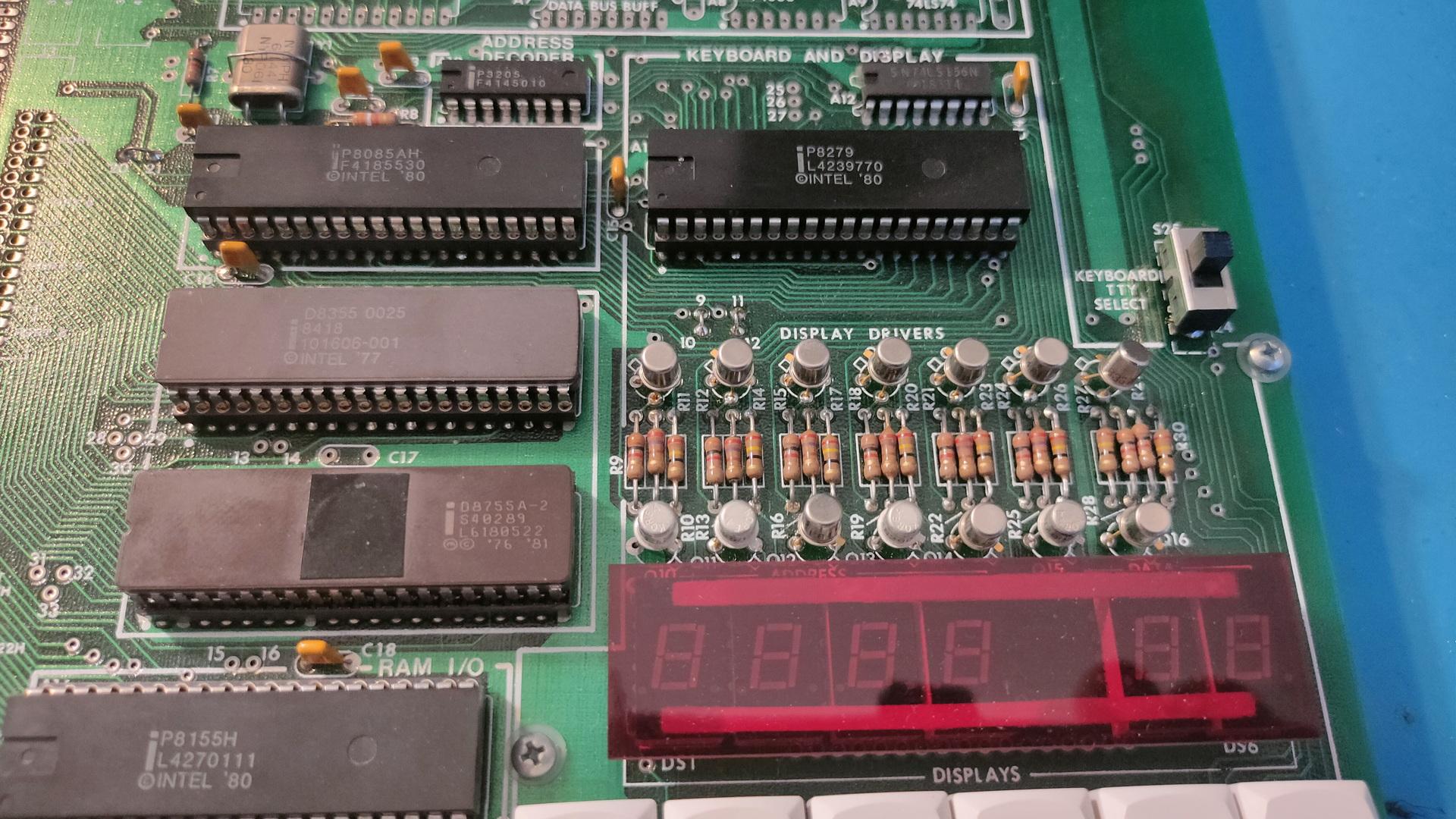
Put little notes in the case with information? Like my SDK-85 case?