<?php
// squeezebox.php
// leave playerid as is, for the default.
// change to MAC address of player to get coverart specific player
$img = file_get_contents('http://IP-LOGITECH_MEDIA_SERVER:9000/music/current/cover.jpg?player=<playerid>');
$im = imagecreatefromstring($img);
$width = imagesx($im);
$height = imagesy($im);
$newwidth = '240';
$newheight = '240';
$thumb = imagecreatetruecolor($newwidth, $newheight);
imagecopyresized($thumb, $im, 0, 0, 0, 0, $newwidth, $newheight, $width, $height);
//imagejpeg($thumb,'small.jpg'); //save image as jpg
header('Content-Type: image/jpeg');
imagejpeg($thumb);
imagedestroy($thumb);
imagedestroy($im);
?>
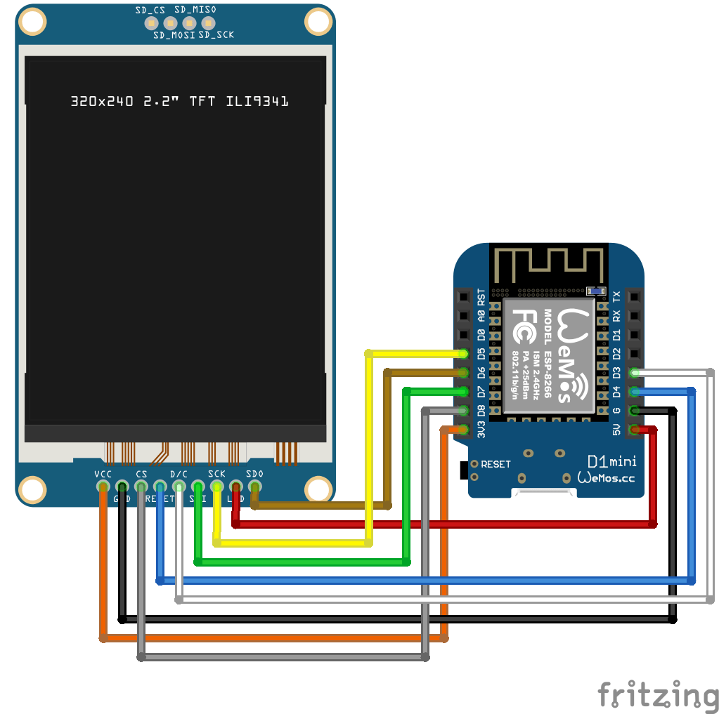
Arduino install:
Start IDE
Install TJpg_Decoder library
Open examples>Tjpeg_decoder>SPIFFS>SPIFFS_web_spiffs
change wifi credentials
and the url to your php script.
  bool loaded_ok = getFile("https://myserver/onkyo.php", "/M81.jpg"); // Note name preceded with "/"

replace bottom part with

 // while(1) yield();
 delay(5000);
     SPIFFS.remove("/M81.jpg");
I was afraid to start this myself, SMD is on another level for me. But my good friend Marco said … No problem!
So I ordered components online, which was not easy. Selecting the correct parts, sizes and options.
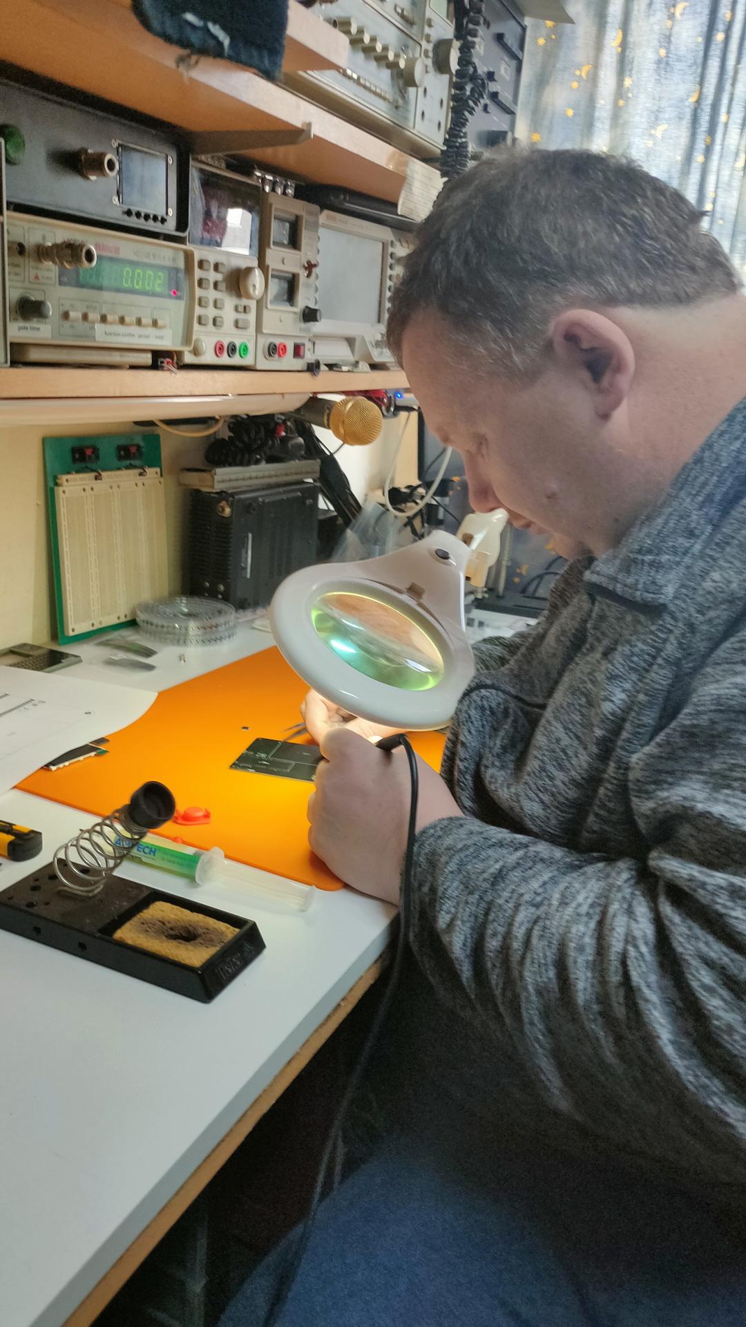
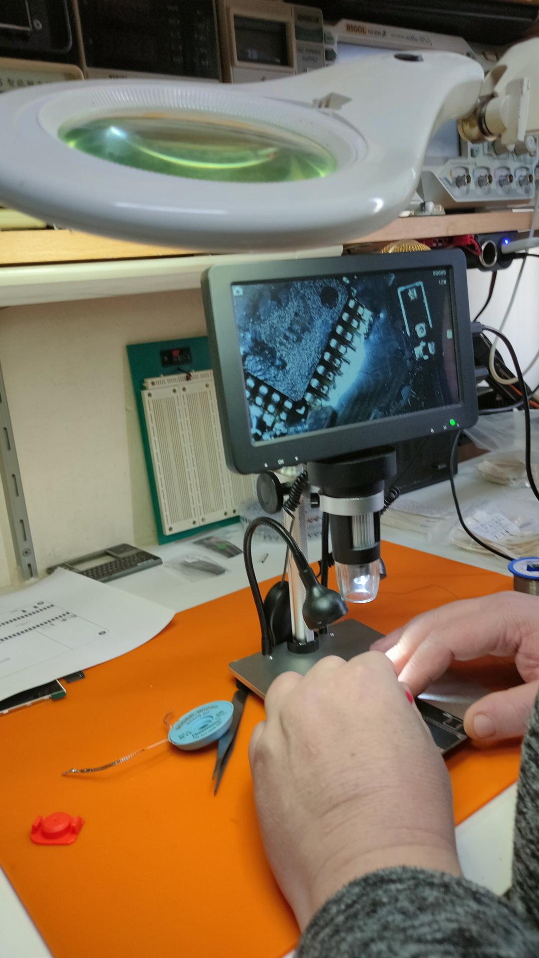
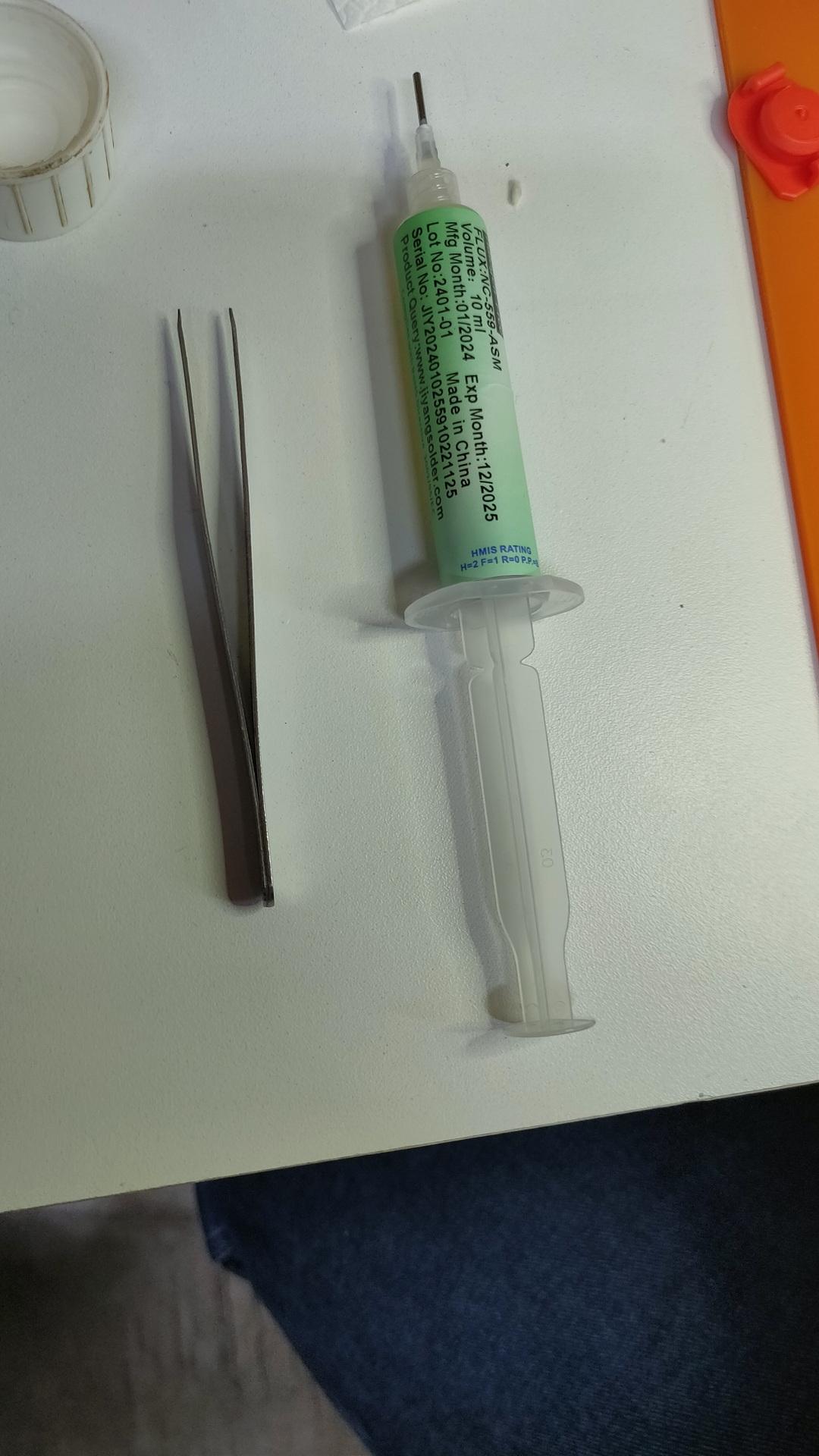
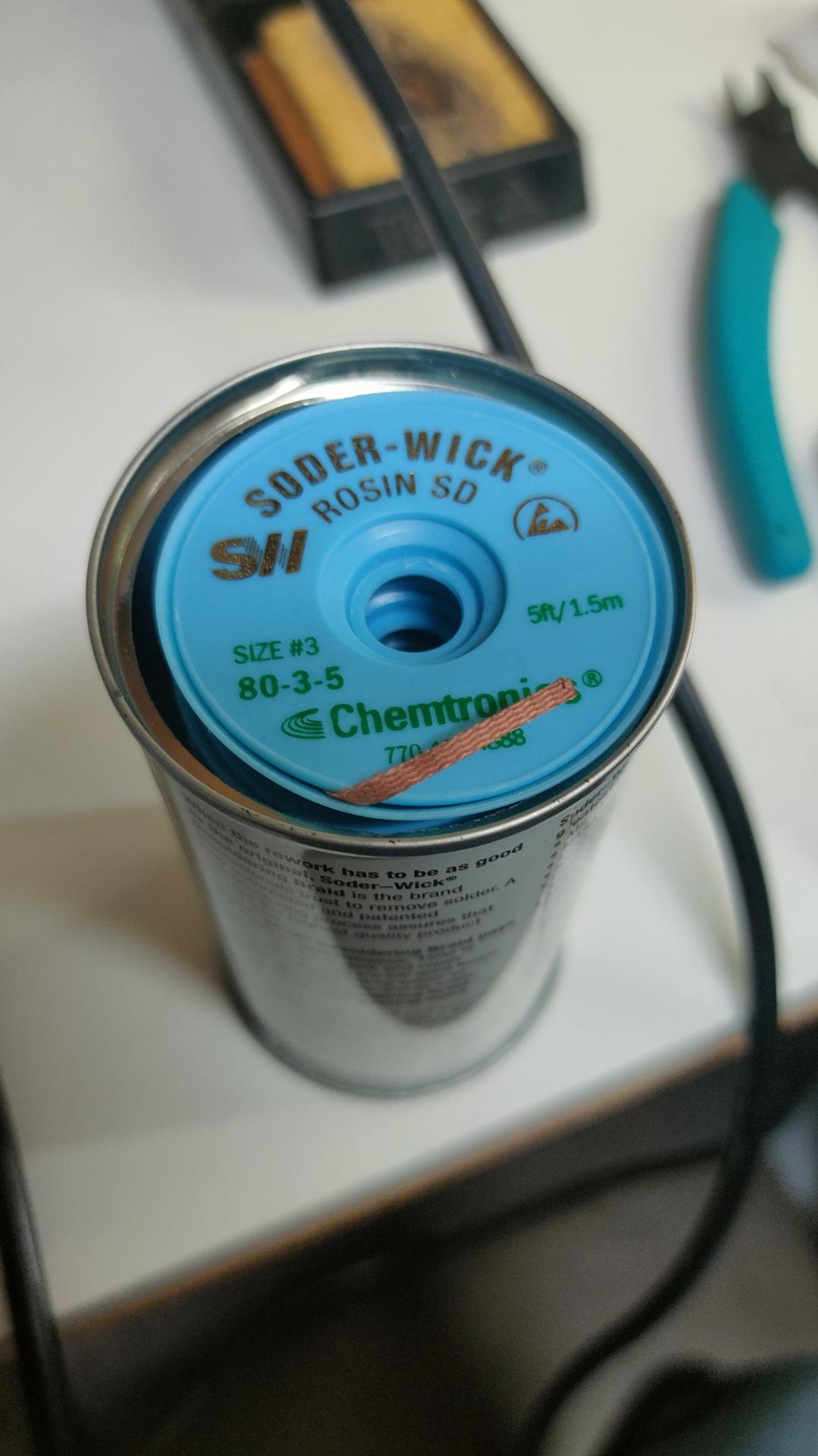
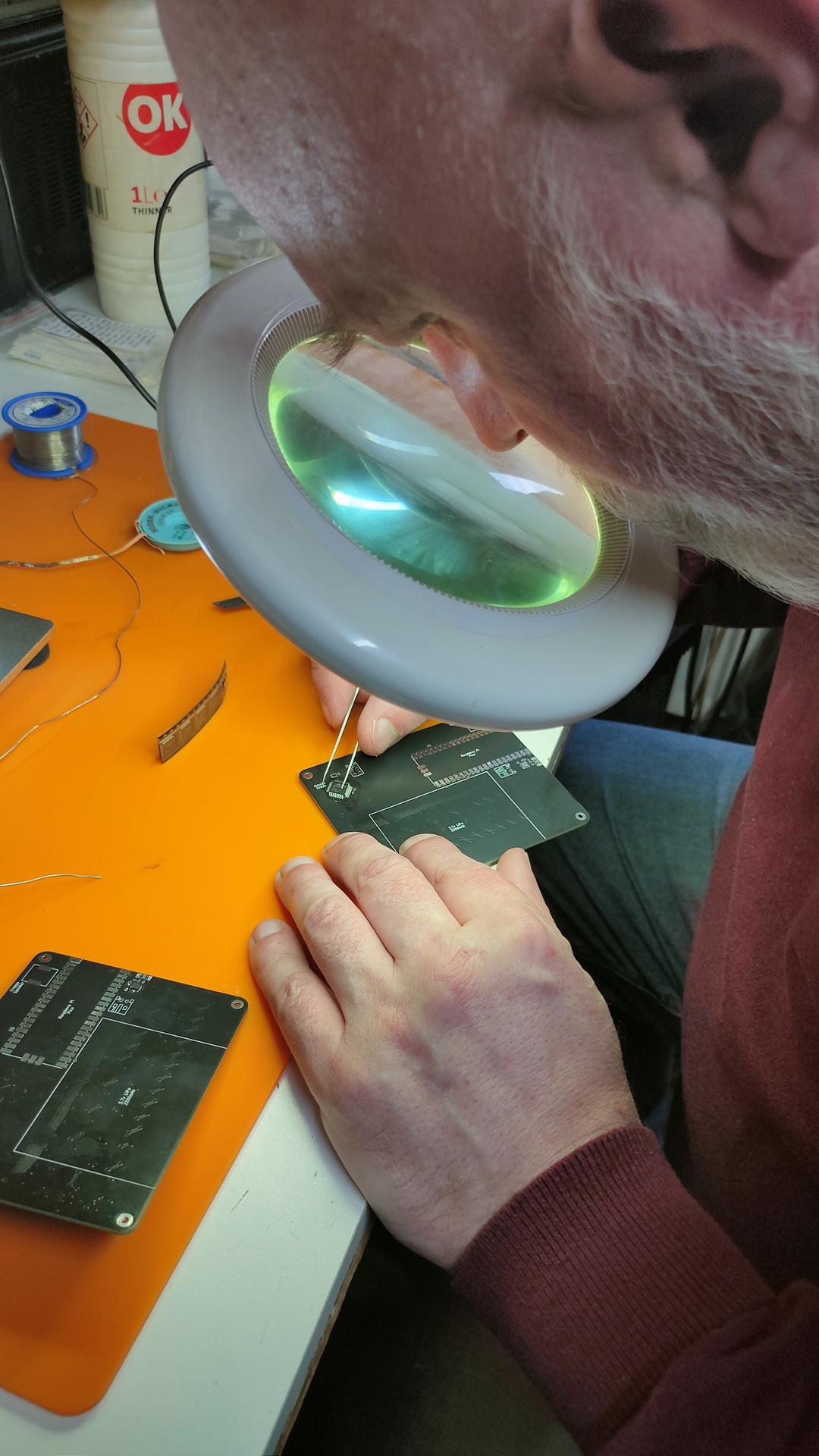
Finding orientations of the componentsThe master at work, he has always been our soldering master (see GPC)Using a microscopeFluxWickI have to do one myself
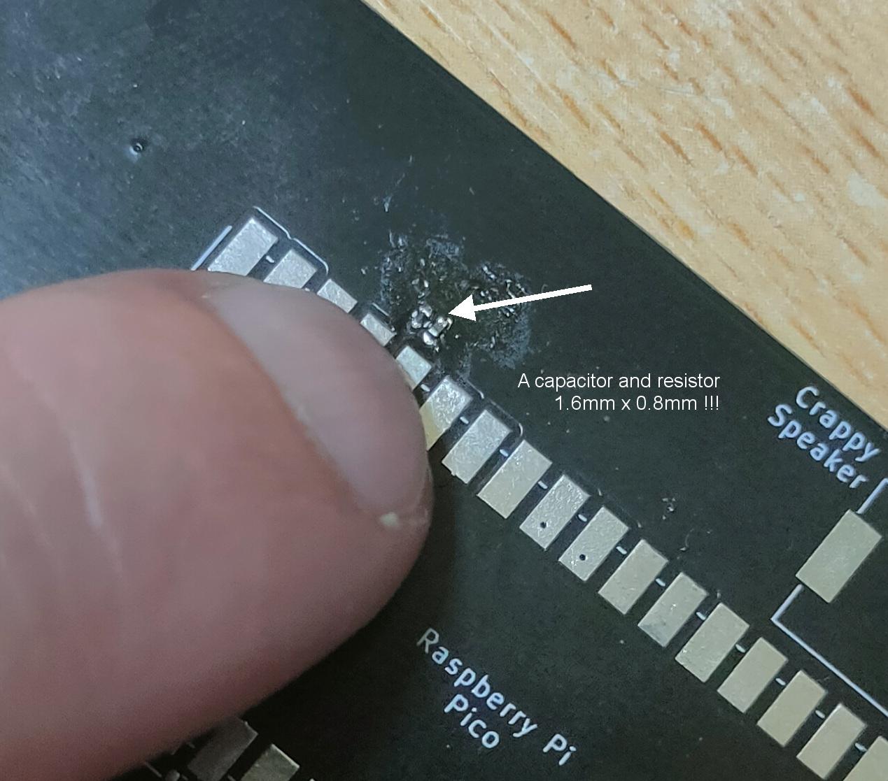
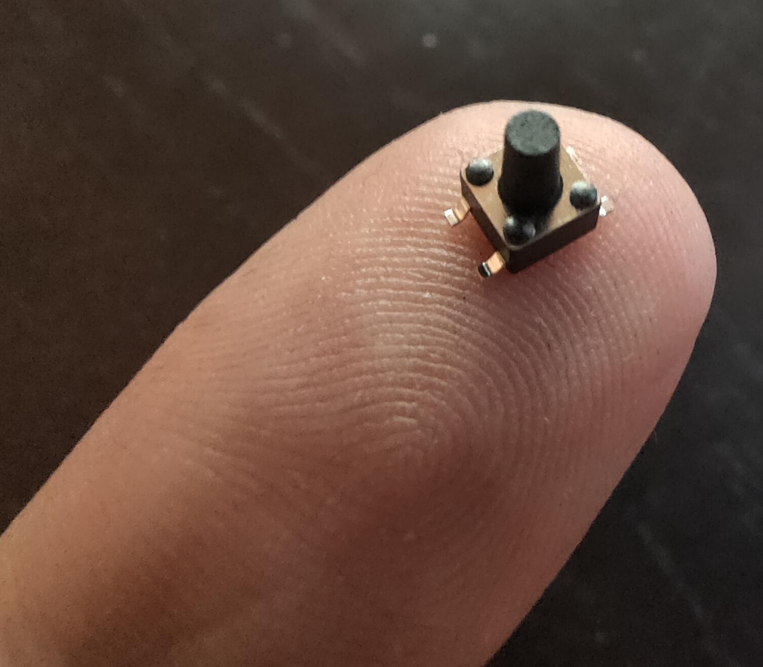
These things are really really small
1.6mm x 0.8mm40 connections / 20mm !
Using tweezers to place the components was even difficult. The slippery tiny bastard got catapulted everywhere. (Or got stuck on fingers, soldering iron and alike) Many small components got lost into the 7th dimension. Never to be found again.
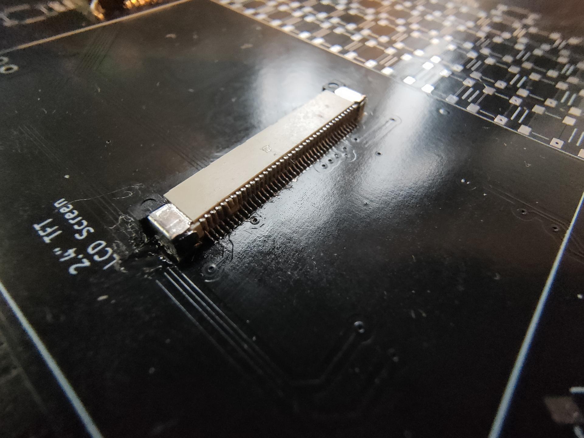
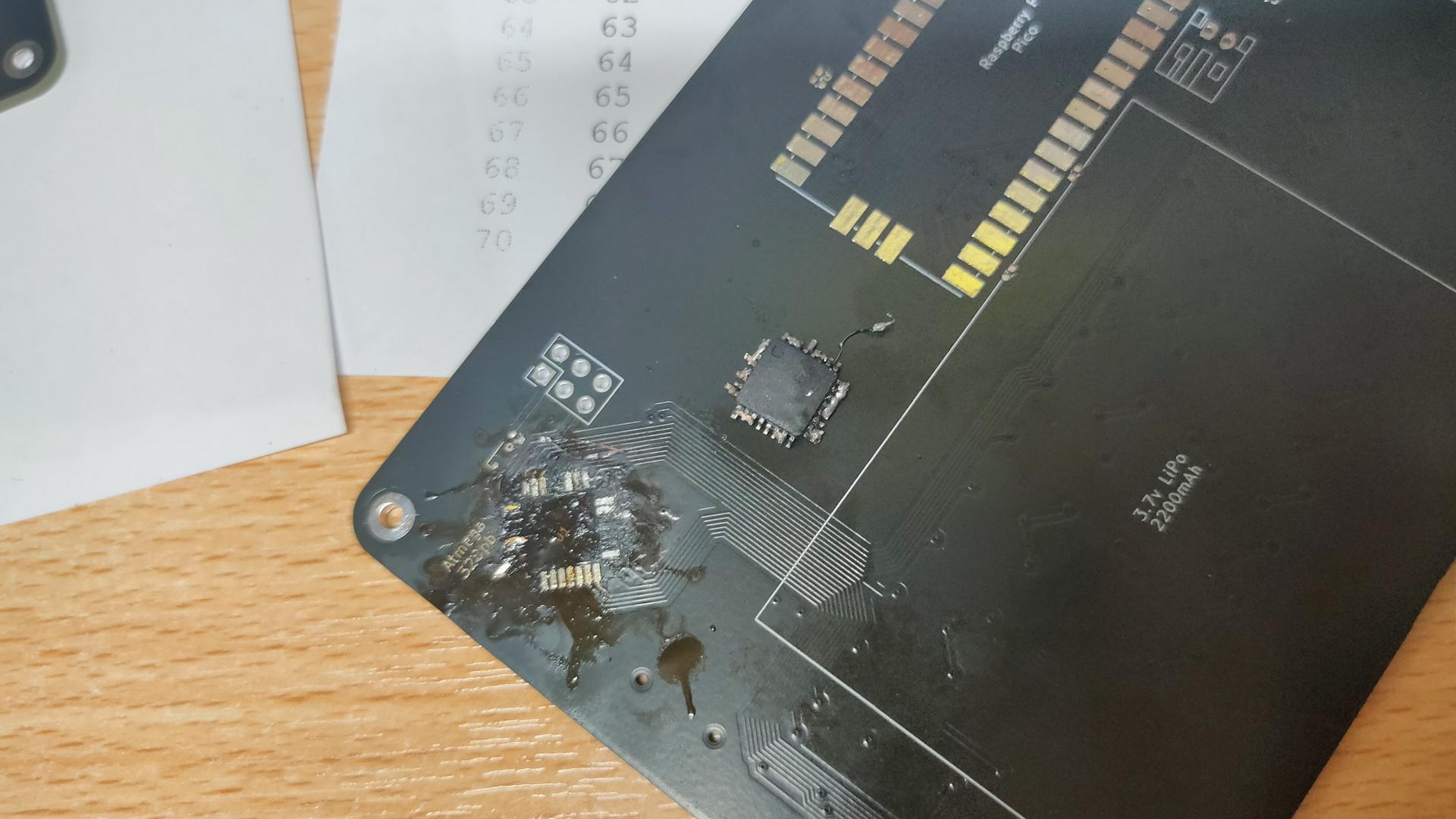
Awesome to work on this together, but Marco said that I have to try it myself. Welllll, I got 3/4 of the ATmega328PB-A perfectly soldered, then I notished that it was crooked. Desoldering was a mess, and I heated the PCB TOO much with the heatgun.
My messed-up PCB, and f*cked-up IC. Leave it to the professionals.
Next step for me is soldering the 75 mini buttons!
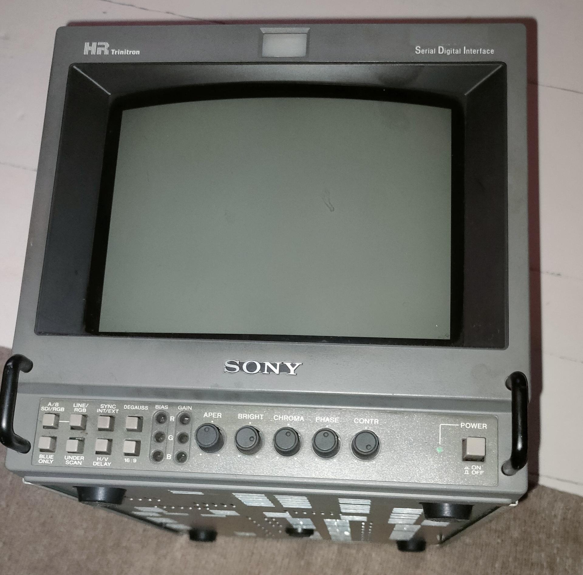
Got a Trinitron display from him, I was looking for this for a long time.
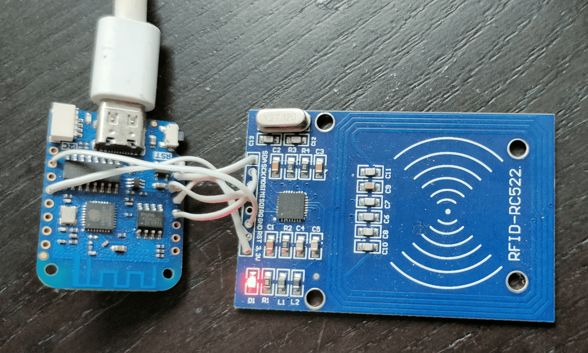
Now, I’ve moved it to Home Assistant using a single automation. (Maybe the Arduino sketch can be made with Esphome also. But I don’t have time for that) It still uses the Arduino sketch as before, which uses Mqtt to post the RFID code to Mosquitto.
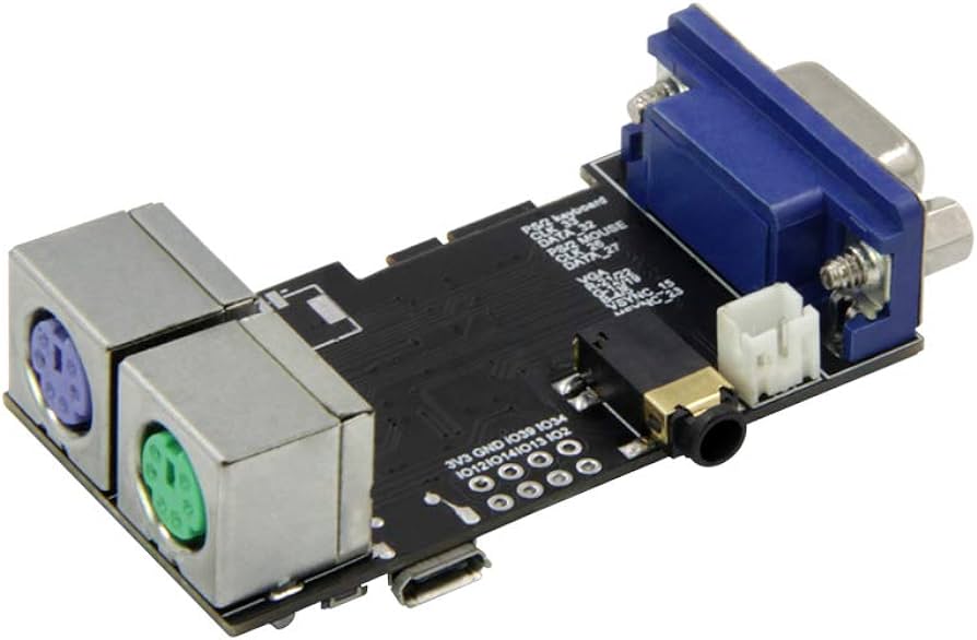
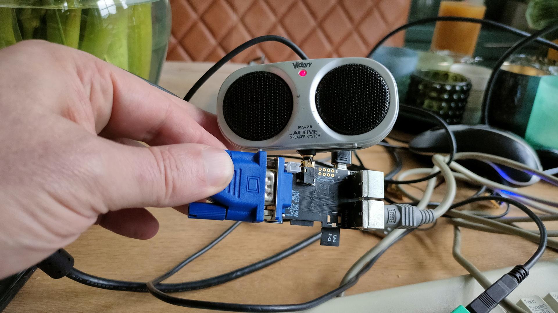
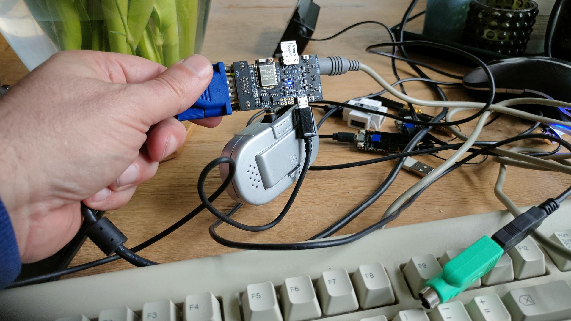
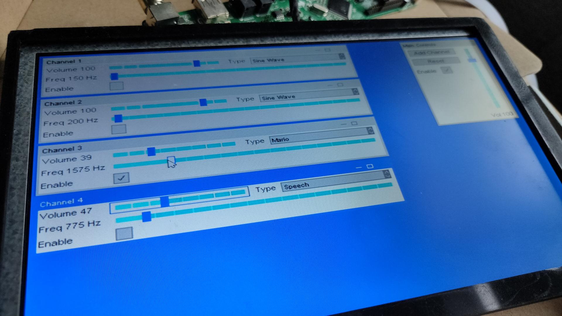
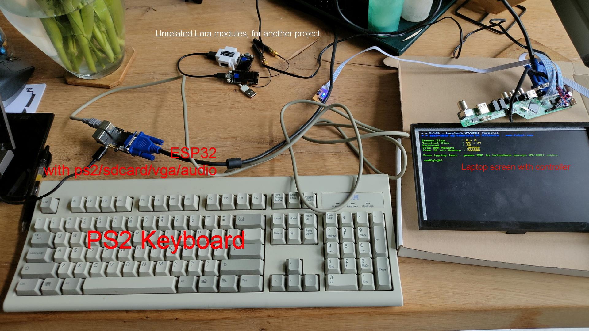
Using the Libraries from Fabrizio Di Vittorio, named FabGL, you can transform this device into a dumb terminal, game device, VIC-20, a 8086 pc and more. There are even some projects to turn this into a C64.
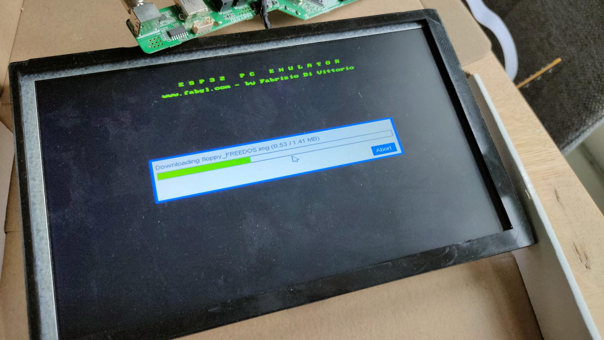
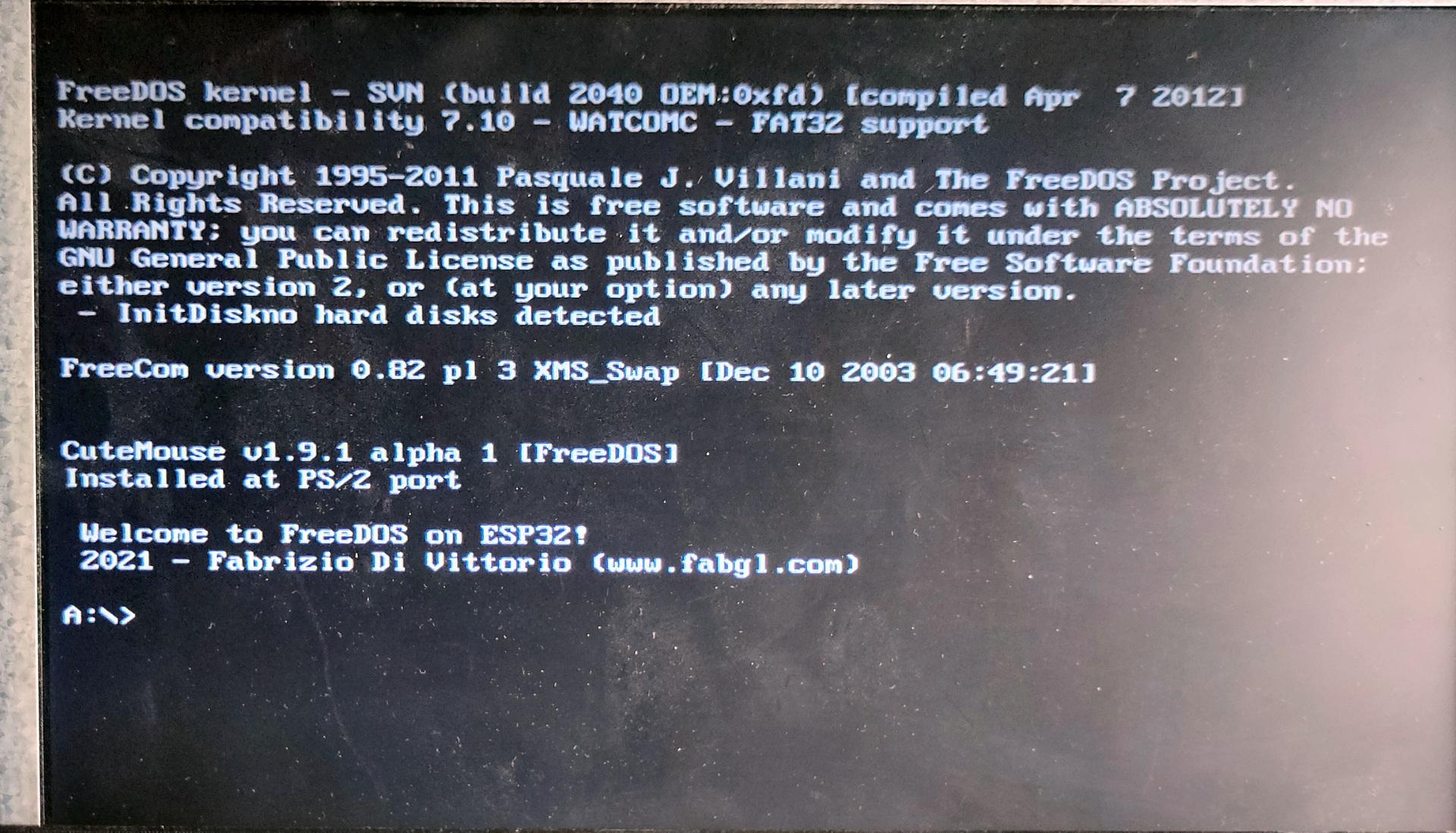
Some generic testing using sound and DOS
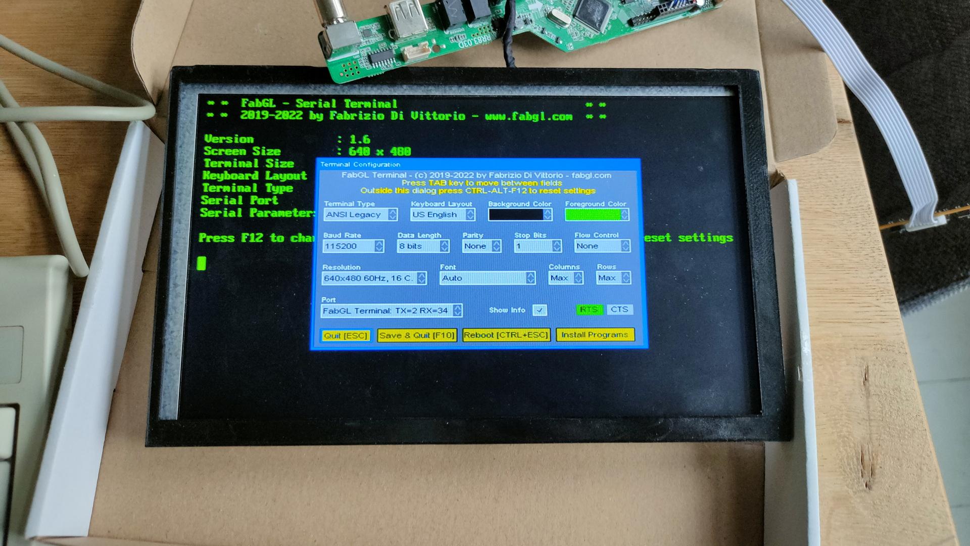
But the main thing I want to do: A simple terminal. (I probably revisit the other options again at a later stage)
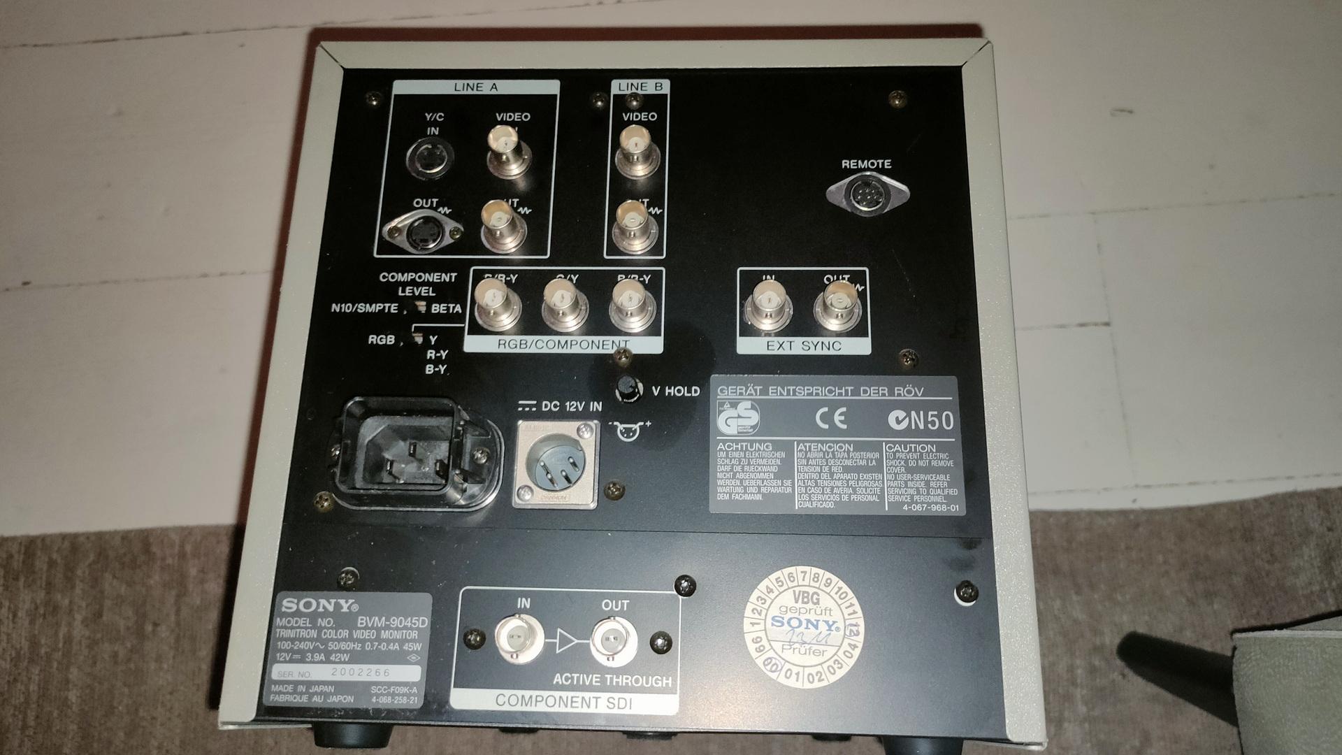
Soldered some pinheaders on the device for serialSome terminal testing.
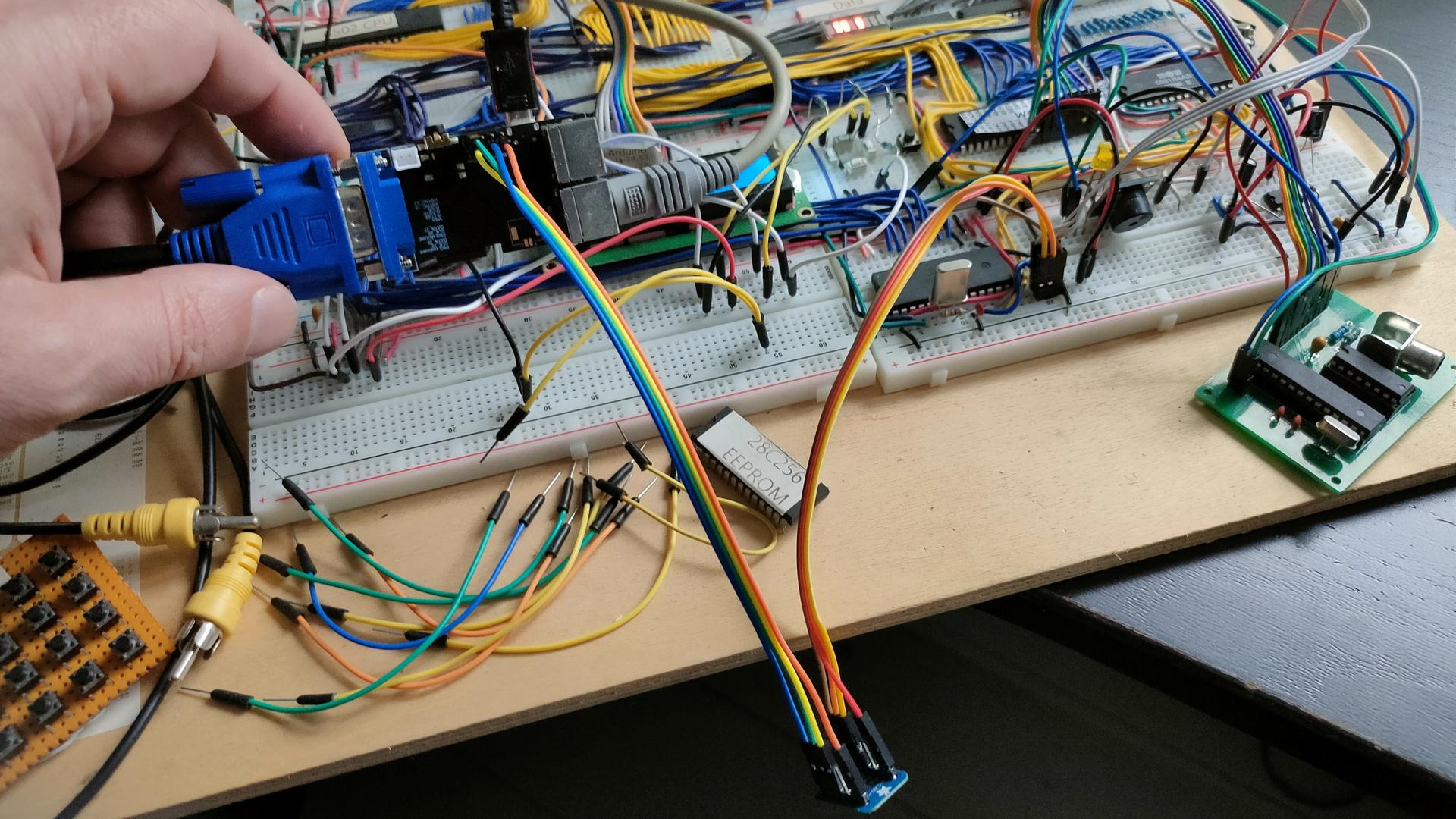
My Wozmon bios has bare minimum support for serial communication, so i have to do some bitbanging. (6502 is using a 6551 ACIA)
At the back the 8 pin single channel lm368 amplifier. At the front the 3 channel setup. I still have to tweak the resistors, and potmeters. Then I can make a permanent PCB, and figure out the connections to the 6502.
At the moment, the Arduino Nano is playing some real sound samples by using the registers of the sound chip. The music is being played by sending the register dumps directly to the chip.
Much like i’ve been using SID register dumps to play songs in another project.
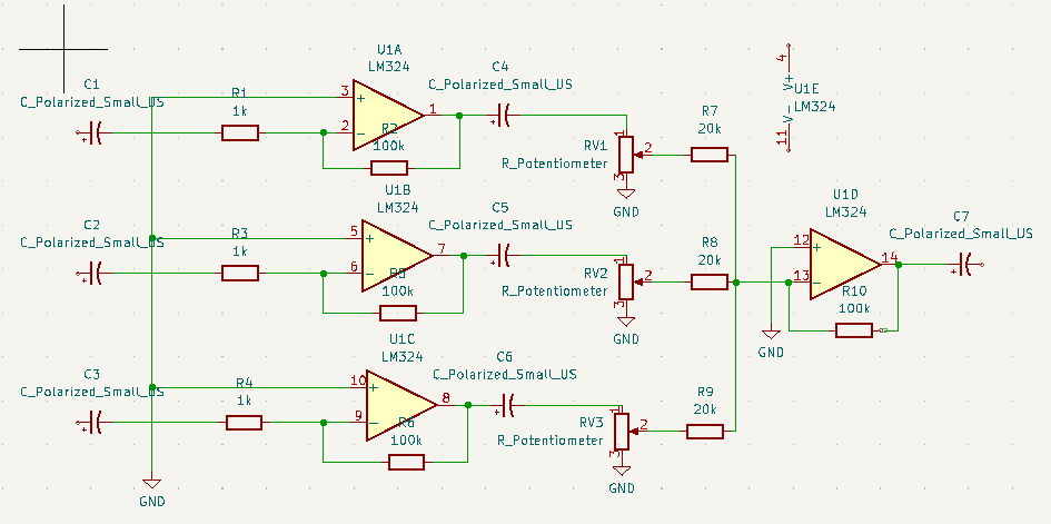
This is version 0.1 .. do not use. If its wrong, or can do better please mail me. Oh it needs a 1k resistor from the 20K’s to ground I think.
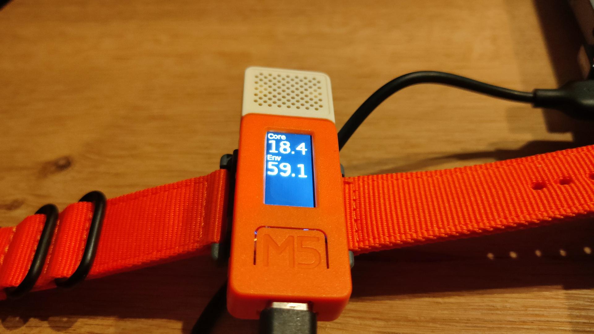
Not posted in the past, new version using ESPHOME and a m5stickc
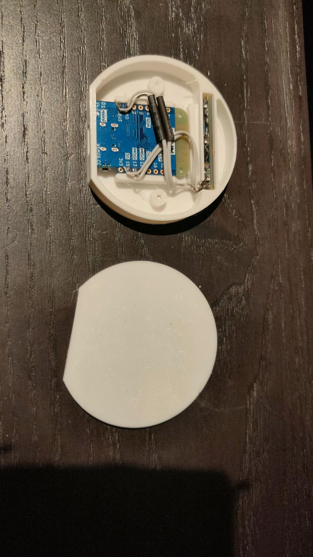
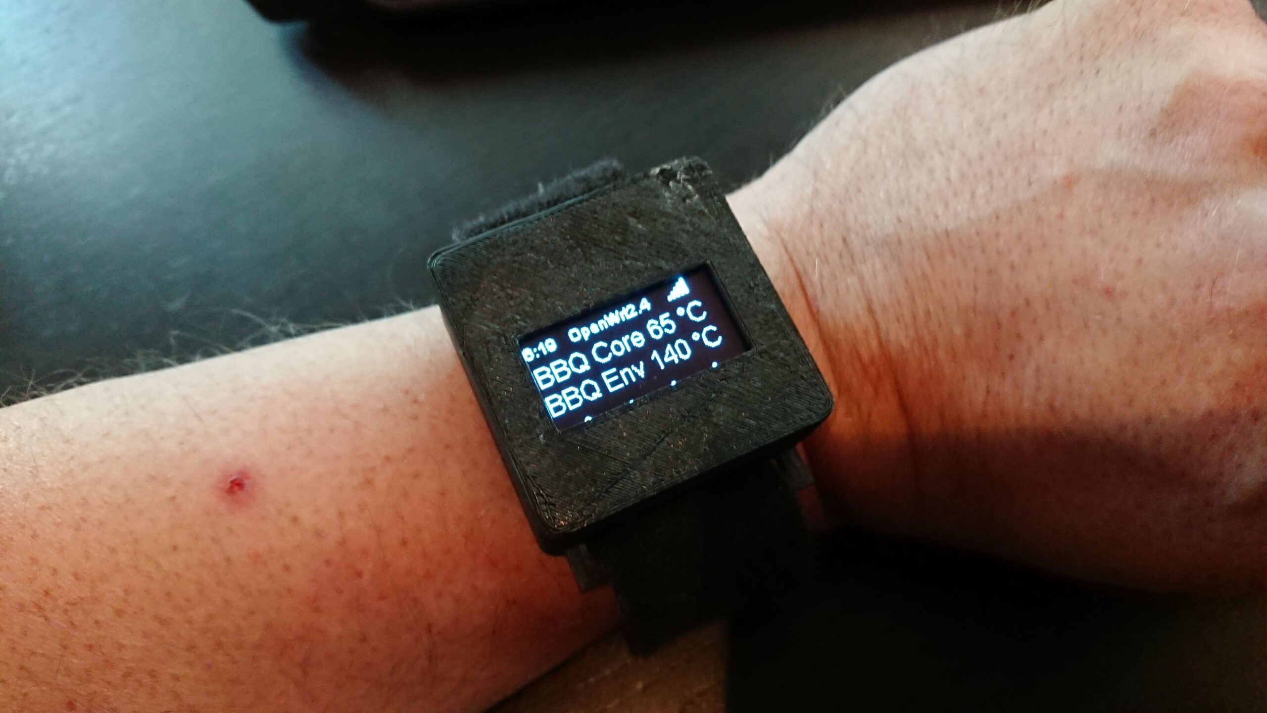
Previous version using a ESP12
A “watch” with core and environment temperature of my smoker with a alarm, and button for timers.
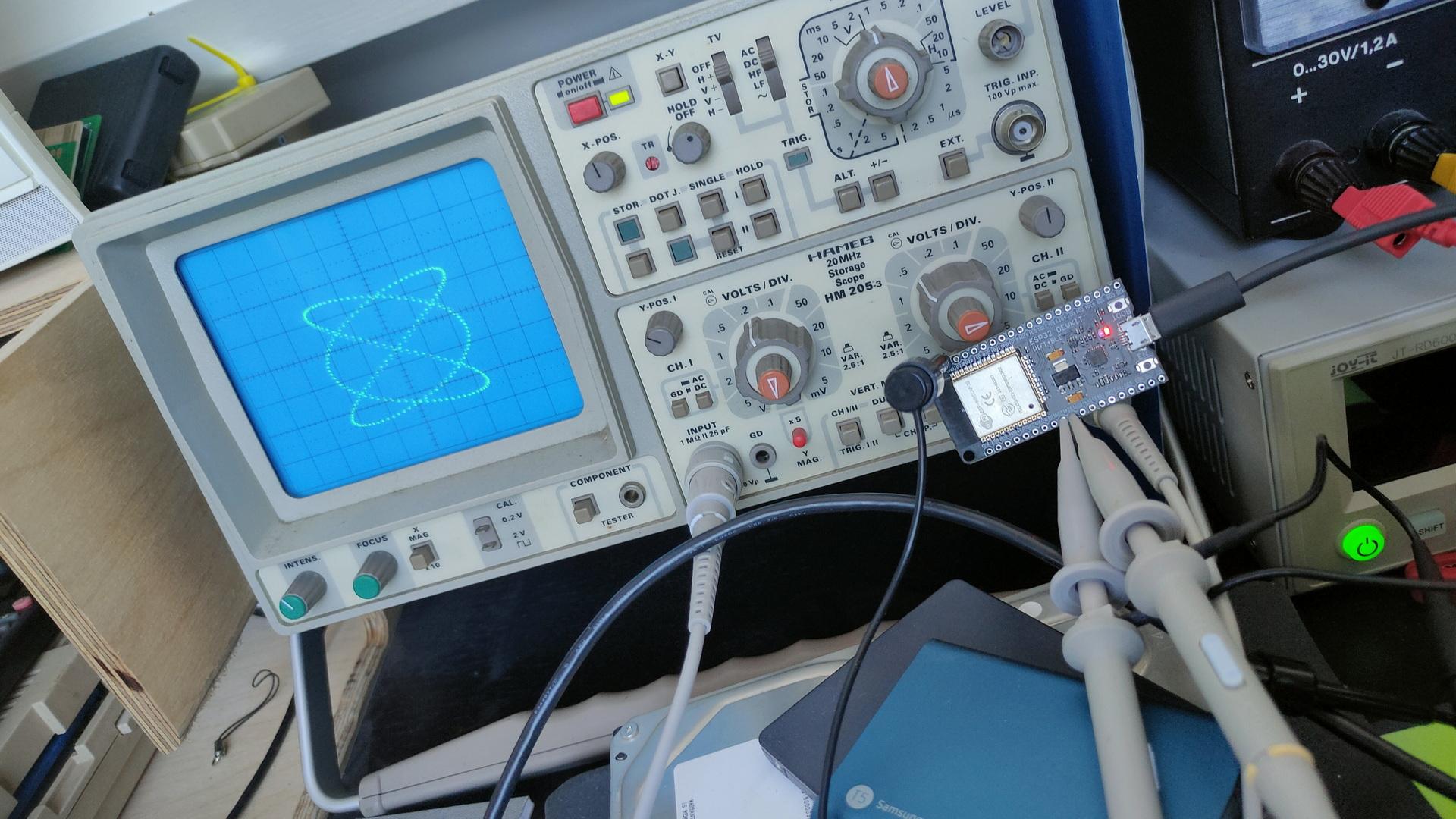
ESP32 dac’s drawing on oscilloscope ( no additional components)
ESP32 in front of scope, two clips for x and y
For above i used sin/cos functions 2:3, which creates Lissajous figures. See: https://www.henriaanstoot.nl/1992/01/01/oscilloscope-graphics-using-a-amiga-bonus-vectrex/
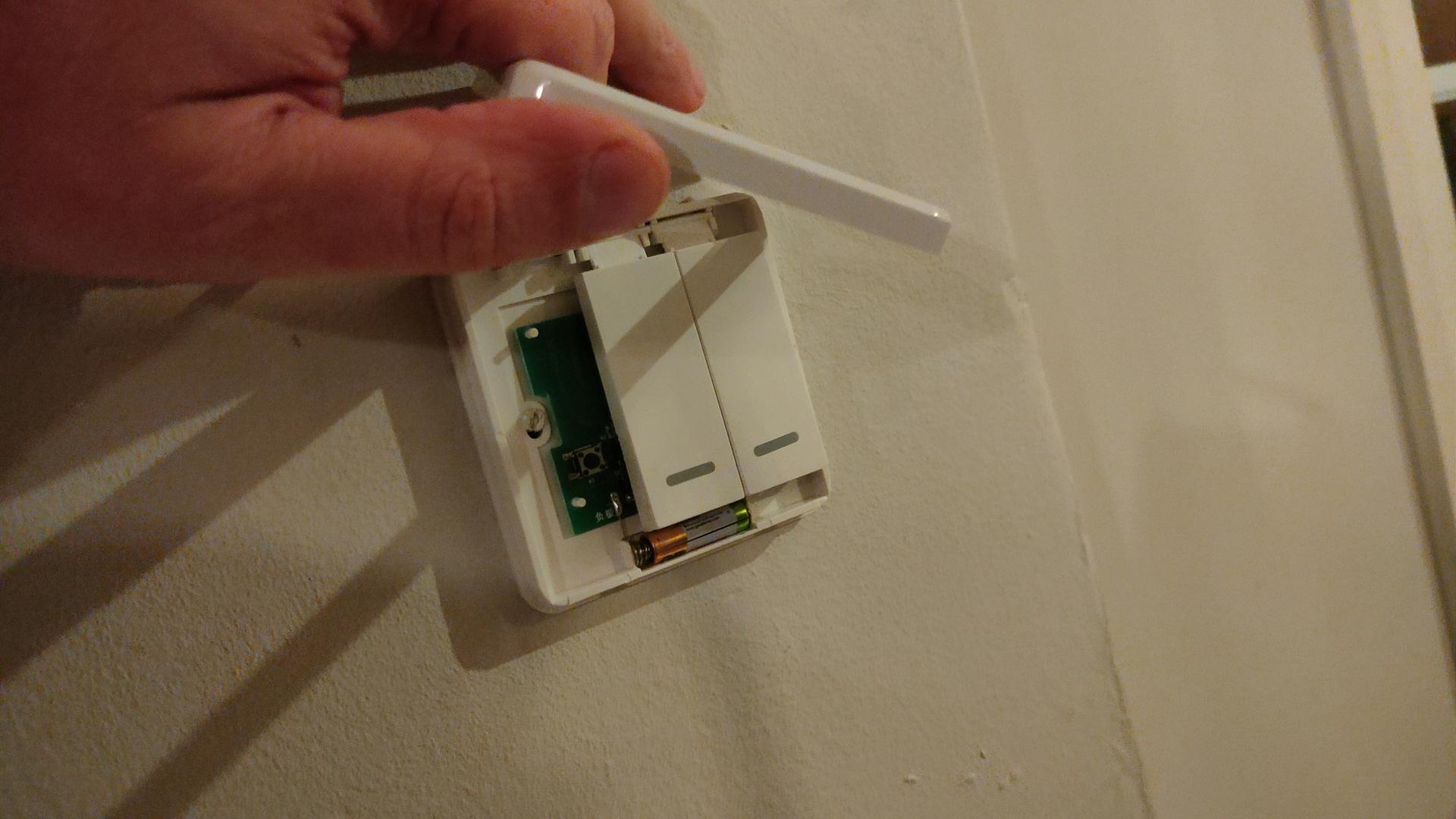
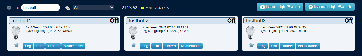
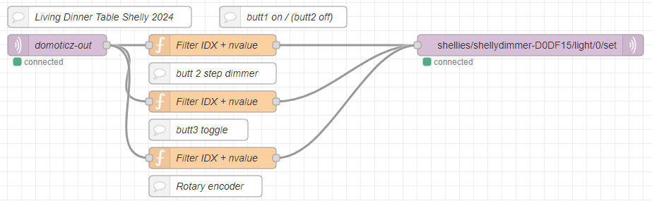
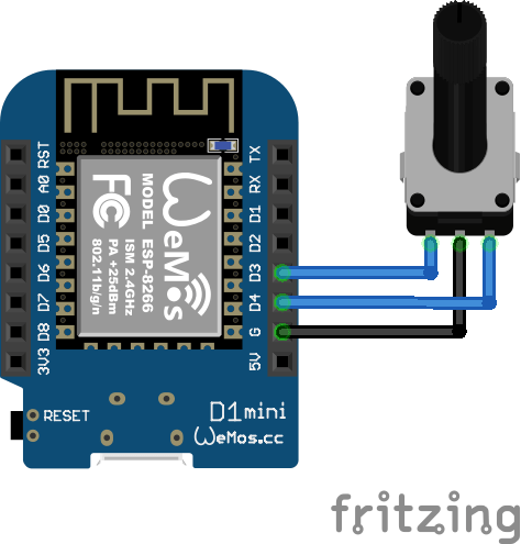
3 battery operated buttons (no wires needed) to control my shelly dimmer at the dinner table.
left button on, middle steps per 20% and 3rd button off. (This cheapass button only sends ON commands)
Posted because I could not find a good example on the interwebs.
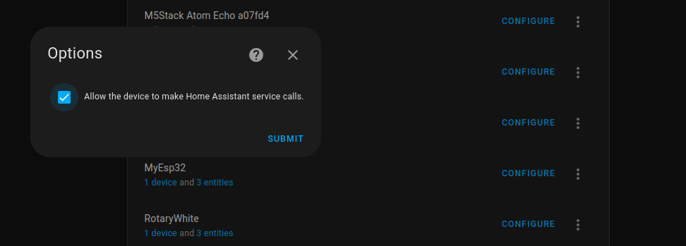
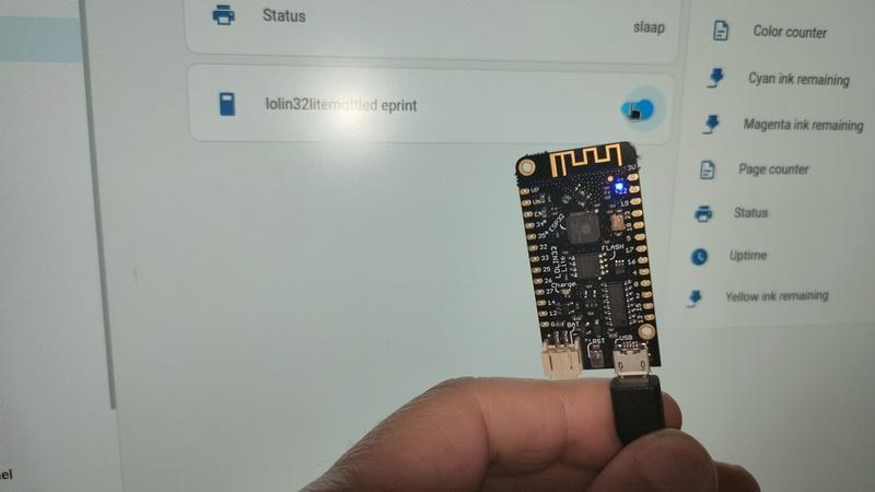
Below creates a virtual HA button which toggles a blinking led. (button and variables are called eprint for another function, change to something meaningful. )
Home Assistant virtual mqtt switch (configuration.yml)
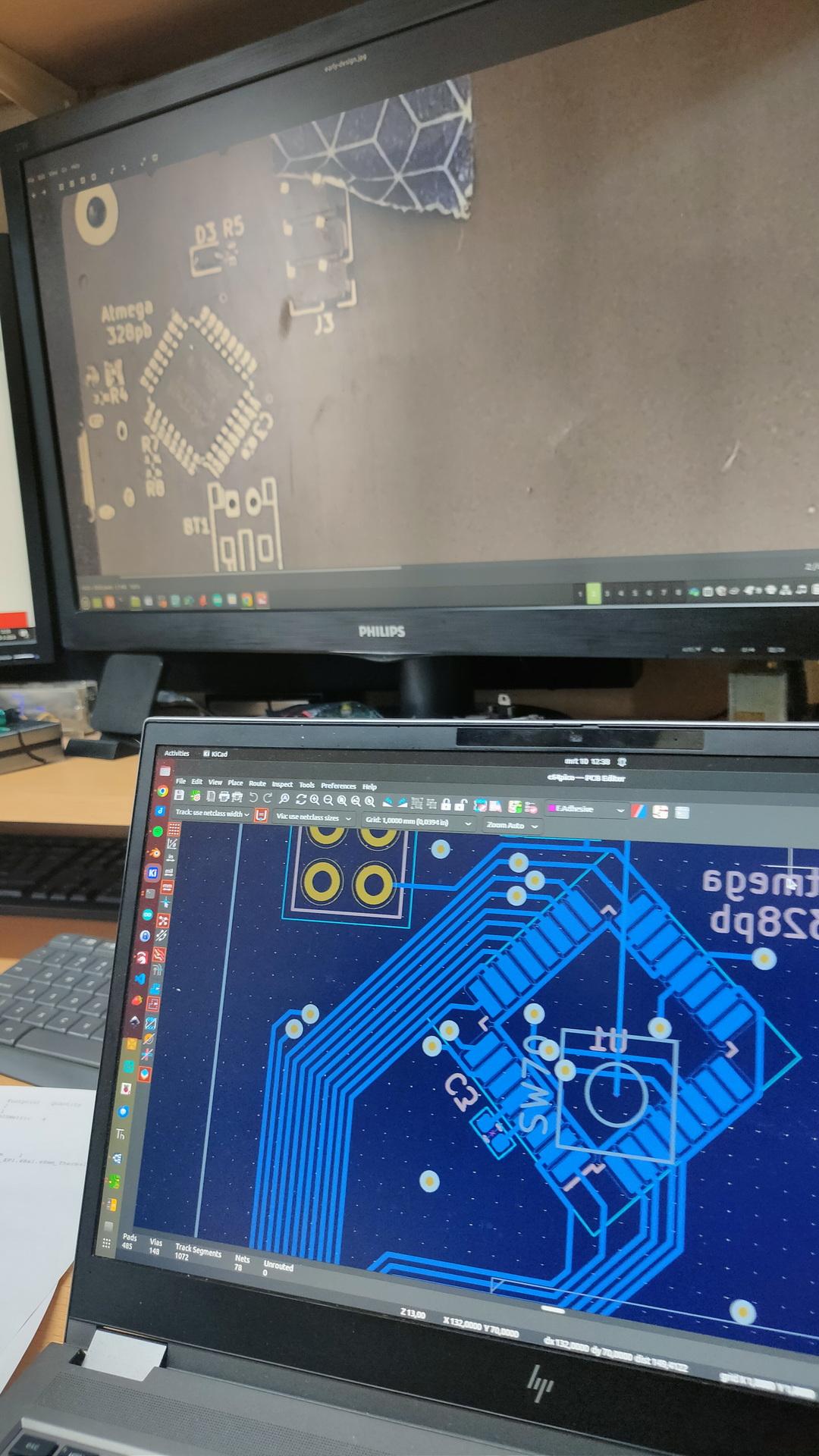
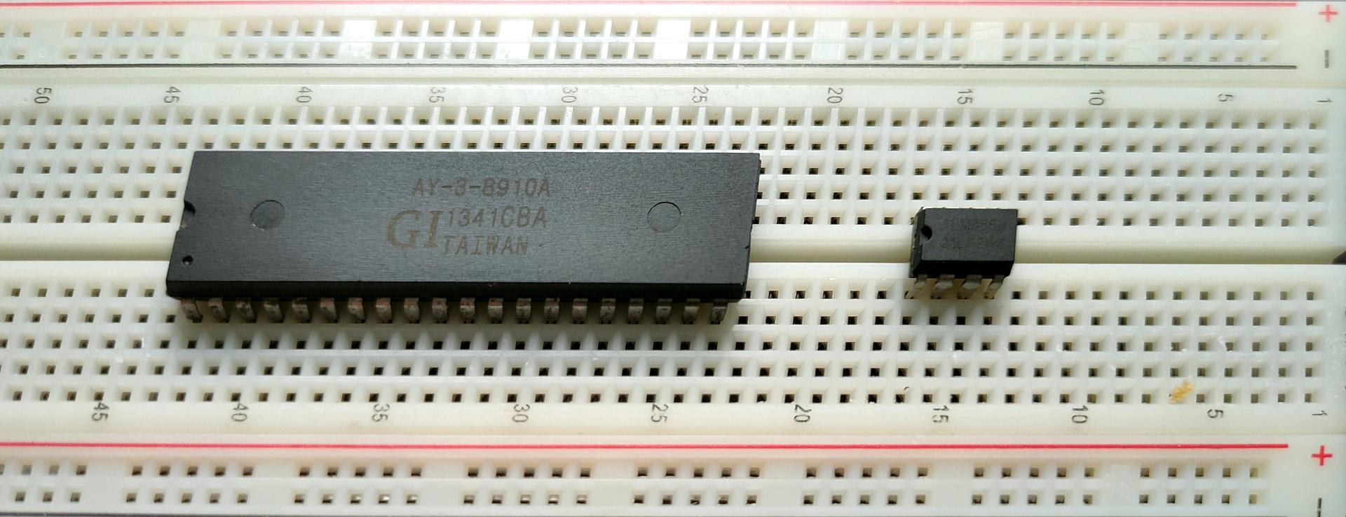
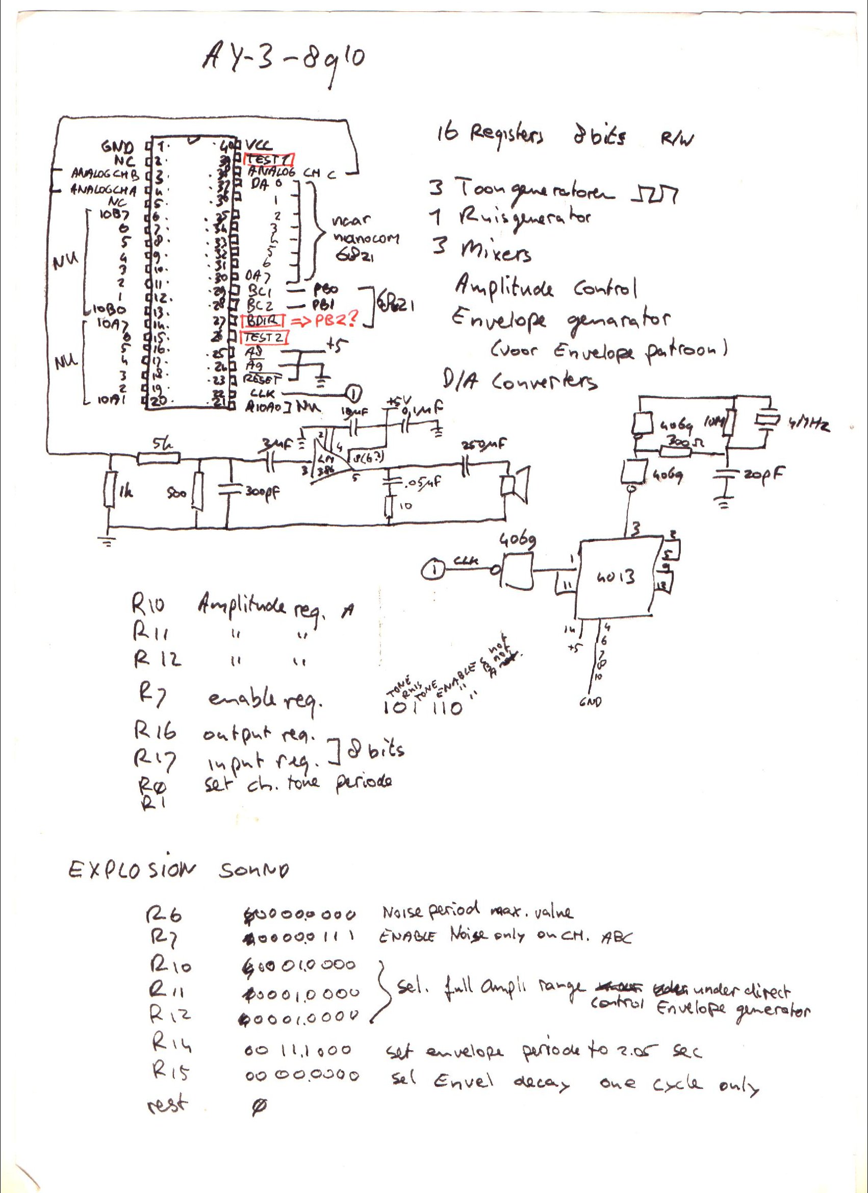
I’ve written about General Instrument AY-3-8910 before, here is some work I did today.
This sound chip i wanted to implement in my amiga, and now it’s a alternative for my 6502 computer. ( As an alternative setup for the SID chip. ) Btw this is the same kind of chip used in the Atari ST.
Above a Kicad drawing I made today, a little different from my design from the 90’s.
Below a movie clip I recorded today. Running a test setup using an Arduino nano and a sdcard reader. The sound is bad, this is due to clipping and the absence of multiple resistors and capacitors. Music is a register dump from a YM music file. Amplifier is a bare LM386.
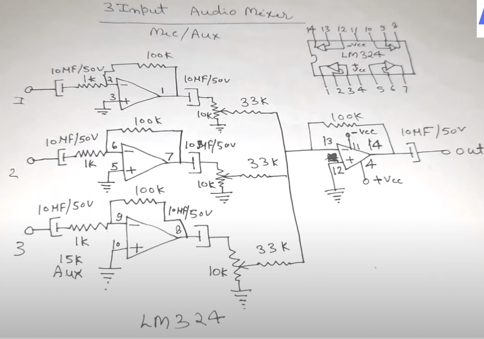
UPDATE: 20240225
I don’t like tying those three outputs together, and amplifying those.
So I’m going to use a LM324 i’ve got left from my 8085 interface, and make a 3-channel amplifier.
Something like this
"If something is worth doing, it's worth overdoing."