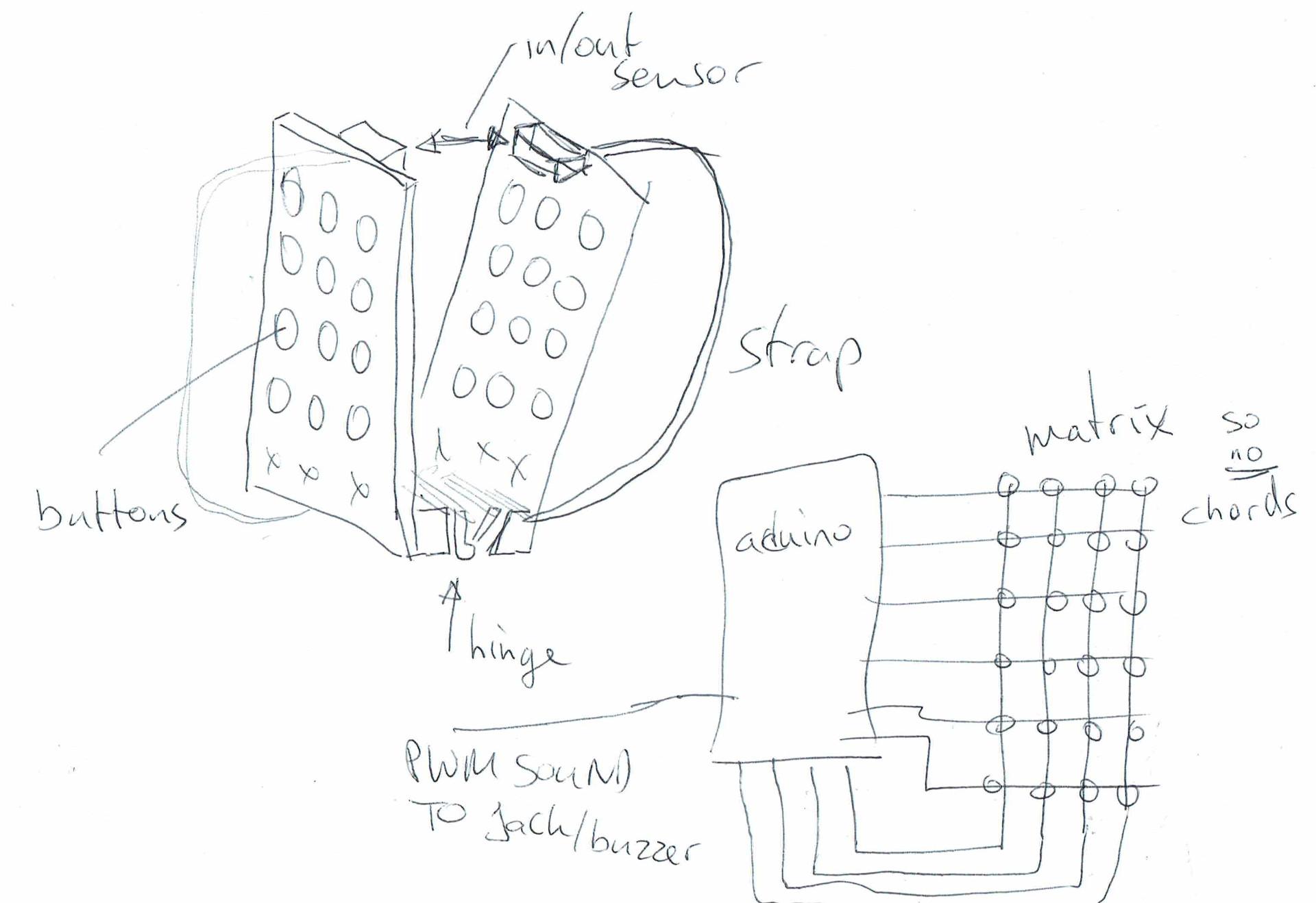
So we need some pushbuttons … at least 14 .. for the most simple tunes. A sensor for push and pull. A buzzer or better yet .. a jack for earphones. Arduino with enough pins to connect a keyboard matrix. When using a keyboard matrix only single keypresses are detected. So we cant do chords!
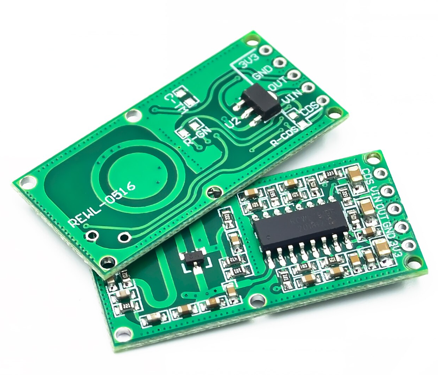
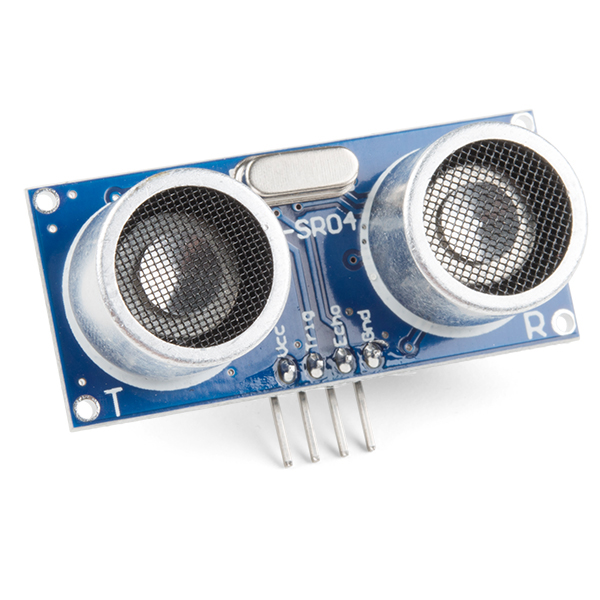
Last year i was playing with this radar module also, but today i made a version with MQTT and a linux client. (There is a project on the internet which uses a HC-SR04, and a arduino connected to the Laptop. This setup is more sensitive and no need for a usb thinghy.)
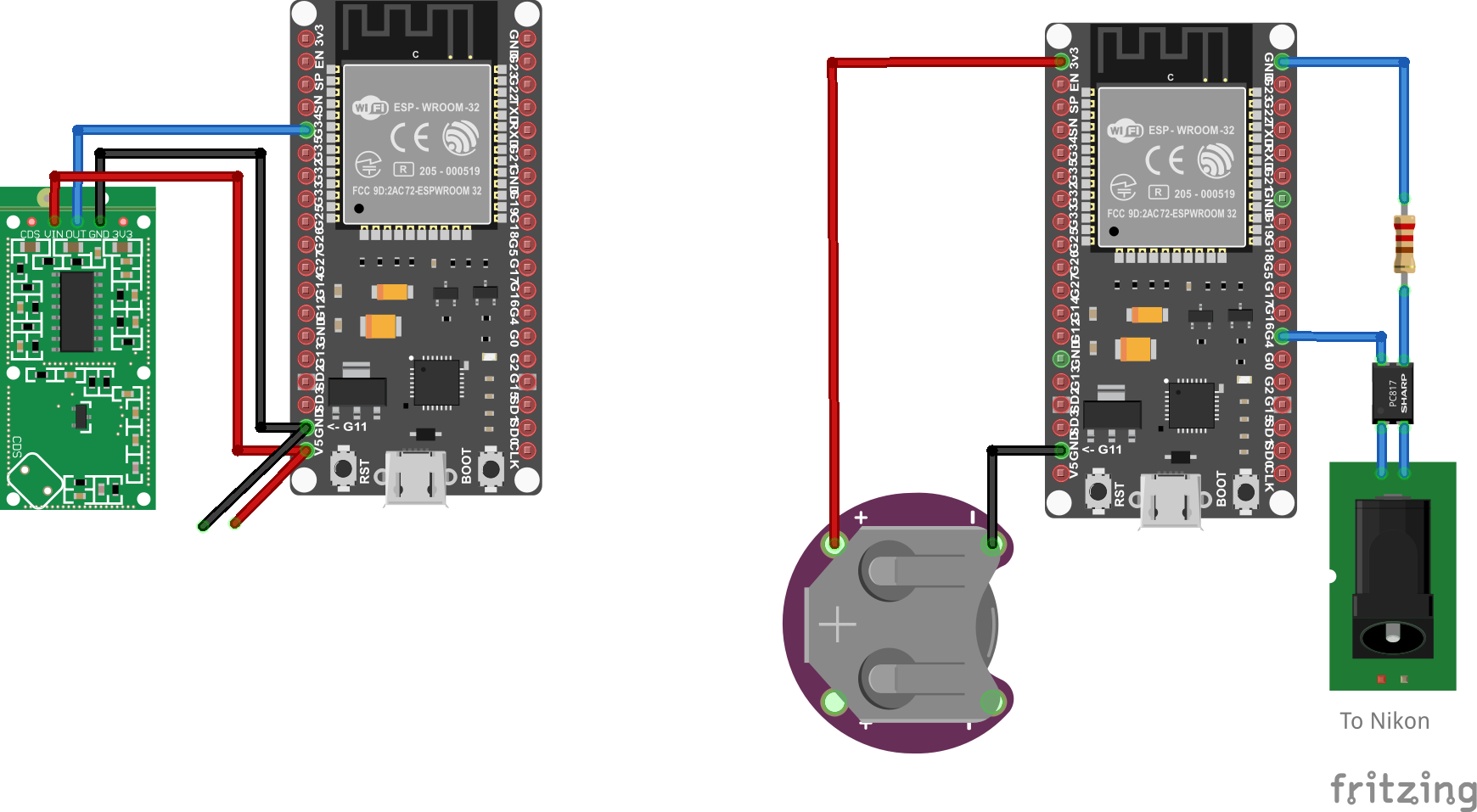
HC-SR04 module (ultrasound)
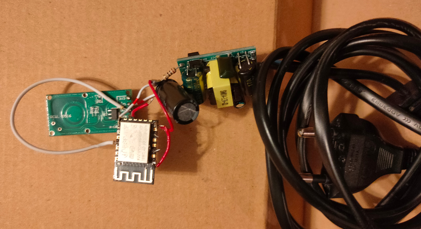
Last years version, using a micro transformer and a ESP-12
When using MQTT i can integrate this in HomeAssistant, Domoticz, NodeRed and more. But i’ve written a python script which runs on my Laptop. For example i can: Kill vlc, change to my work desktop, stop sound output and lock the screen. (everything you can script)
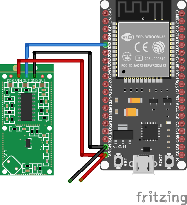
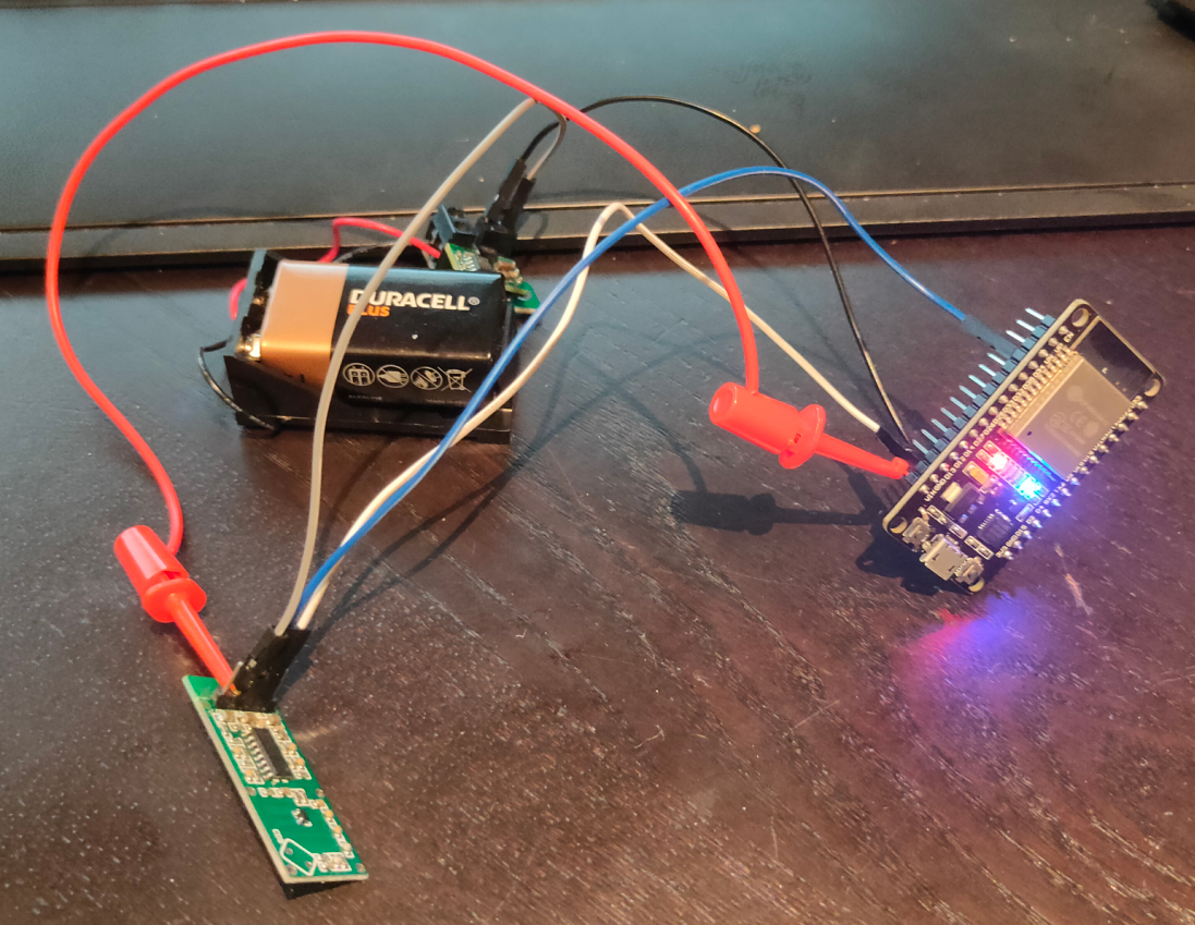
I wanted to have a “mobile” version of the sensor so i can place it anywhere. (Frontdoor, gardengate, candydrawer 🙂 )
These modules are very cheap, but do their job well!
I’ve used a Wroom ESP32 and a BattBorg together with the module, that’s it.
Below shows the speed of detection, and sending though the network
Python script which does a lock-screen using XDOTOOL
from paho.mqtt import client as mqtt_client
import subprocess
import time

broker = 'MQTT-SERVER'
port = 1883
topic = "radar/state"
client_id = "radarclient"

def connect_mqtt() -> mqtt_client:
    def on_connect(client, userdata, flags, rc):
        if rc == 0:
            print("Connected to MQTT Broker!")
        else:
            print("Failed to connect, return code %d\n", rc)

    client = mqtt_client.Client(client_id)
    client.on_connect = on_connect
    client.connect(broker, port)
    return client

def subscribe(client: mqtt_client):
    def on_message(client, userdata, msg):
        state = msg.payload.decode()
        print (state)
        if state == "1":
            subprocess.Popen(["xdotool","key","Super_L+l"])
            time.sleep(30)


    client.subscribe(topic)
    client.on_message = on_message

def run():
    client = connect_mqtt()
    subscribe(client)
    client.loop_forever()

if __name__ == '__main__':
    run()
change subprocess.Popen([“xdotool”,”key”,”Super_L+l”]) into subprocess.Popen([“switchdesktop”]) to run a script named switchdesktop
#!/bin/bash
# This is the switchdesktop script, it goes to the next screen using winows-page-down combo
xdotool key "Super_L+Page_Down"
Todo:
3D print a case Make a version which becomes a Access Point. Then make another arduino setup which controls my Nikon. So it can act like a wildcam (offline)
Something like below, using a optocoupler ( i still got some leftovers from my doorbell to gpio-pin project.)
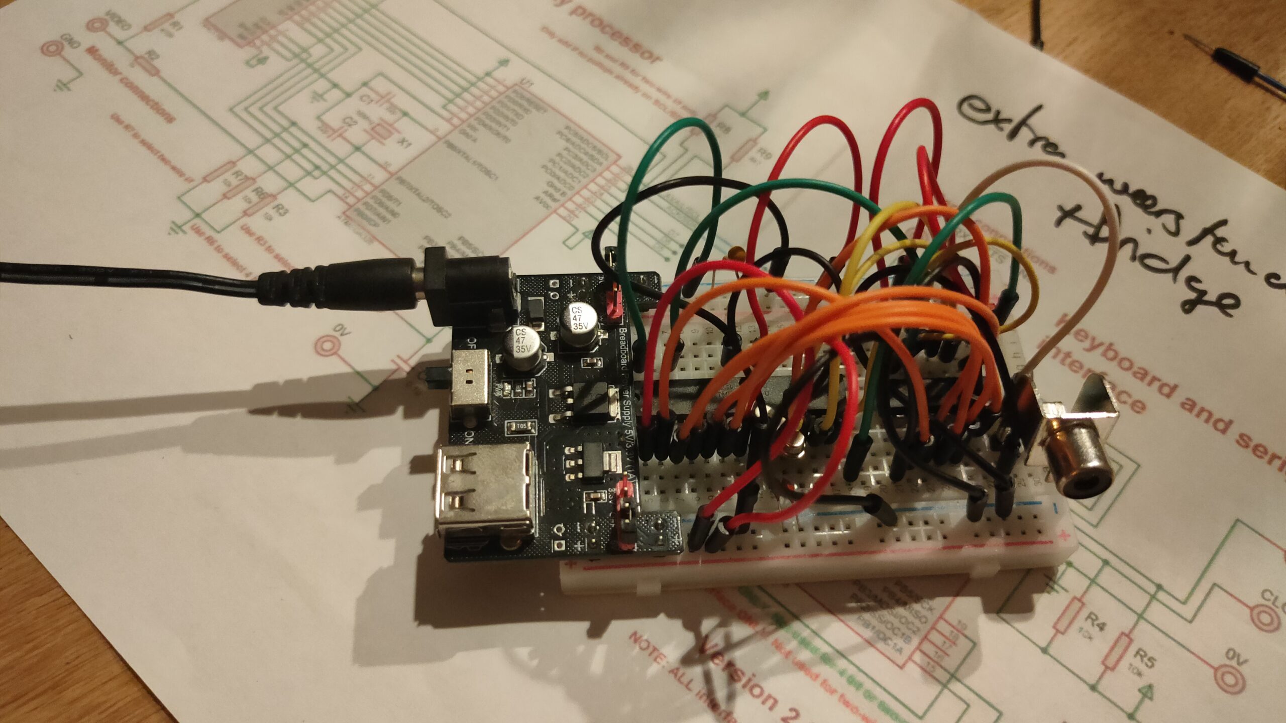
I started to get some composite video generated with a arduino for my 6502 project.
UPDATE: 20221021
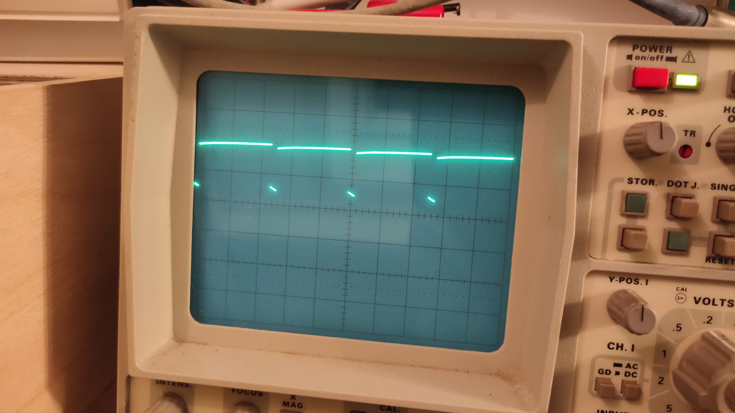
It is based on Grant Searle’s design, and yesterday I had some signals on my scope which looked like a screen with a character. But my monitor would not recognize a usable signal.
Today I tried a second version and another set of chips and crystals.
It looks like a signal, but I can’t see a clock pulse from the crystal?! So .. how?
Maybe I used a bad power supply. And killed something?
UPDATE: 20221021
After switching to another power supply, and checking the atmega328p fuses again (also wrong) .. at least SOME success!
Still a little sync problem, but i’ve got a blinking cursor!
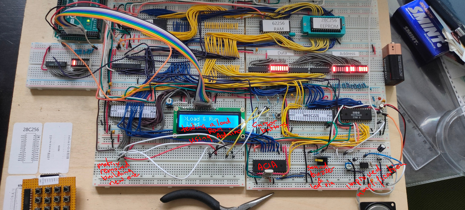
Buzzer and led on VIA 2, blinky and sound timed by the internal timers of the 6522
ACIA testing still going on, writing software
Mini matrix keyboard removed, and used the temporary cursor buttons for the test with a rom which allows for a 8bits upload method using a arduino and the 6522. (I’m working on the big keyboard)
Work in progress code
PORT2B = $5000 		; VIA PORTB
PORT2A = $5001 		; VIA PORTA
DDR2B = $5002  		; Data direction register
DDR2A = $5003  		; Data direction register

PORTB = $6000 		; display
PORTA = $6001 		; control display + matrix keyboard
DDRB = $6002  		; data direction register
DDRA = $6003  		; data direction register
SID = $7000   		; sid base address

E  = %10000000		; enable bit
RW = %01000000		; RW bit
RS = %00100000		; Register Select bit
HOME = %00000010 	; VIA PORTB HOME command
DADDR = %00010000 	; VIA DADDRESS

LINENO = $0200		; temp address linenumber (move to other location)
NEXTLINE = 40		; 2x16 Chars but internally 40


  .org $8000

reset:
  ldx #$ff
  txs		; reset stack

; ###################################################
; #                 DISPLAY CONTROL                 #
; ###################################################
; VIA Setup

  lda #%11111111 	; Set all pins on port B to output
  sta DDRB
  lda #%11100000 	; Set top 3 pins on port A to output
  sta DDRA

; DISPLAY Setup
  lda #%00111000 	; Set 8-bit mode; 2-line display; 5x8 font
  jsr lcd_instruction
  lda #%00001110 	; Display on; cursor on; blink off
  jsr lcd_instruction
  lda #%00000110 	; Increment and shift cursor; don't shift display
  jsr lcd_instruction
  lda #$00000001 	; Clear display
  jsr lcd_instruction

; ###################################################
; #             PRINT MESSAGE LINE NO 0             #
; ###################################################
  lda #0  		; set line number
  sta LINENO      	; store for subroutine
  jsr gotoline		; move cursor

  ldx #0		; message index pointer
print:
  lda message0,x 	; start of message
  beq nextprint      	; stop when null in message (asciiz <- Zero padded)
  jsr print_char	; print char
  inx			; incr index
  jmp print		; resume print
; ###################################################
; #             PRINT MESSAGE LINE NO 1             #
; ###################################################
nextprint:
  lda #1  		; set line number
  sta LINENO      	; store
  jsr gotoline
  ldx #0  		; index pointer
print2:
  lda message1,x  	; absolute address message + x in A
  beq sidsound        	; if x is 0, end of message
  jsr print_char  	; jump subroutine
  inx             	; increment x
  jmp print2      	; loop print2


; ###################################################
; #             SID SOUND                           #
; ###################################################
sidsound:
  lda #0
  sta SID+$5		; attack/decay duration

  lda #250
  sta SID+$6		; sustain level/release duration

  lda #$95		; frequency voice 1 low byte
  sta SID+$0

  lda #$44		; frequency voice 1 high byte
  sta SID+$1

  lda #%00100001	; sawtooth + gate
  sta SID+$4		; control register voice 1

  lda #$0f		; filter mode and volume (bits 3-0 main volume)
  sta SID+$18		; filter mode and volume


; ###################################################
; #             2ND VIA                             #
; ###################################################
  lda #%11111111 	; set port A output
  sta DDR2A

  lda #%11111111	; all ones!
  sta PORT2A
; ###################################################
  lda #%11111111 	; set port A output
  sta DDR2A

  lda #%11111111	; all ones!
  sta PORT2A


; ###################################################
; #             MAIN PROGRAM LOOP                   #
; ###################################################
loop:
  jmp loop
;                   1234567812345678
message0: .asciiz  "VIA 1,2 SID TEST"
message1: .asciiz  "   FASH  2022   "

; ###################################################
; #             ONLY SUBROUTINES                    #
; ###################################################

; ###################################################
; #             Subroutine gotoline                 #
; # Moves character placement position on display   #
; # Needs : $LINENO ADDRESS                         #
; # Exit values : -                                 #
; # Destroys registers: -                           #
; ###################################################

gotoline:
  pha                             ; store a
  txa
  pha                             ; store x
  ldx LINENO
  lda #HOME                       ; cursor down
  jsr lcd_instruction
  lda #$80
nextline:
  ldx LINENO
  cpx #00
  beq endnextlines
loopline:
  adc #40
  jsr lcd_instruction
  dex
  stx LINENO
  jmp nextline
endnextlines:
  pla                             ; pop a
  tax                             ; a to x
  pla                             ; pop a
  rts


; ###################################################
; #             LCD SUBROUTINES                     #
; ###################################################
lcd_wait:
  pha
  lda #%00000000  ; Port B is input
  sta DDRB
lcdbusy:
  lda #RW
  sta PORTA
  lda #(RW | E)
  sta PORTA
  lda PORTB
  and #%10000000
  bne lcdbusy
  lda #RW
  sta PORTA
  lda #%11111111  ; Port B is output
  sta DDRB
  pla
  rts
lcd_instruction:
  jsr lcd_wait
  sta PORTB
  lda #0         ; Clear RS/RW/E bits
  sta PORTA
  lda #E         ; Set E bit to send instruction
  sta PORTA
  lda #0         ; Clear RS/RW/E bits
  sta PORTA
  rts
print_char:
  jsr lcd_wait
  sta PORTB
  lda #RS         ; Set RS; Clear RW/E bits
  sta PORTA
  lda #(RS | E)   ; Set E bit to send instruction
  sta PORTA
  lda #RS         ; Clear E bits
  sta PORTA
  rts

nmi:
  rti

irq:
  rti

  .org $fffa
  .word nmi
  .word reset
  .word irq
;  .word $0000
In this case designed for my 6502, but it is a generic setup.
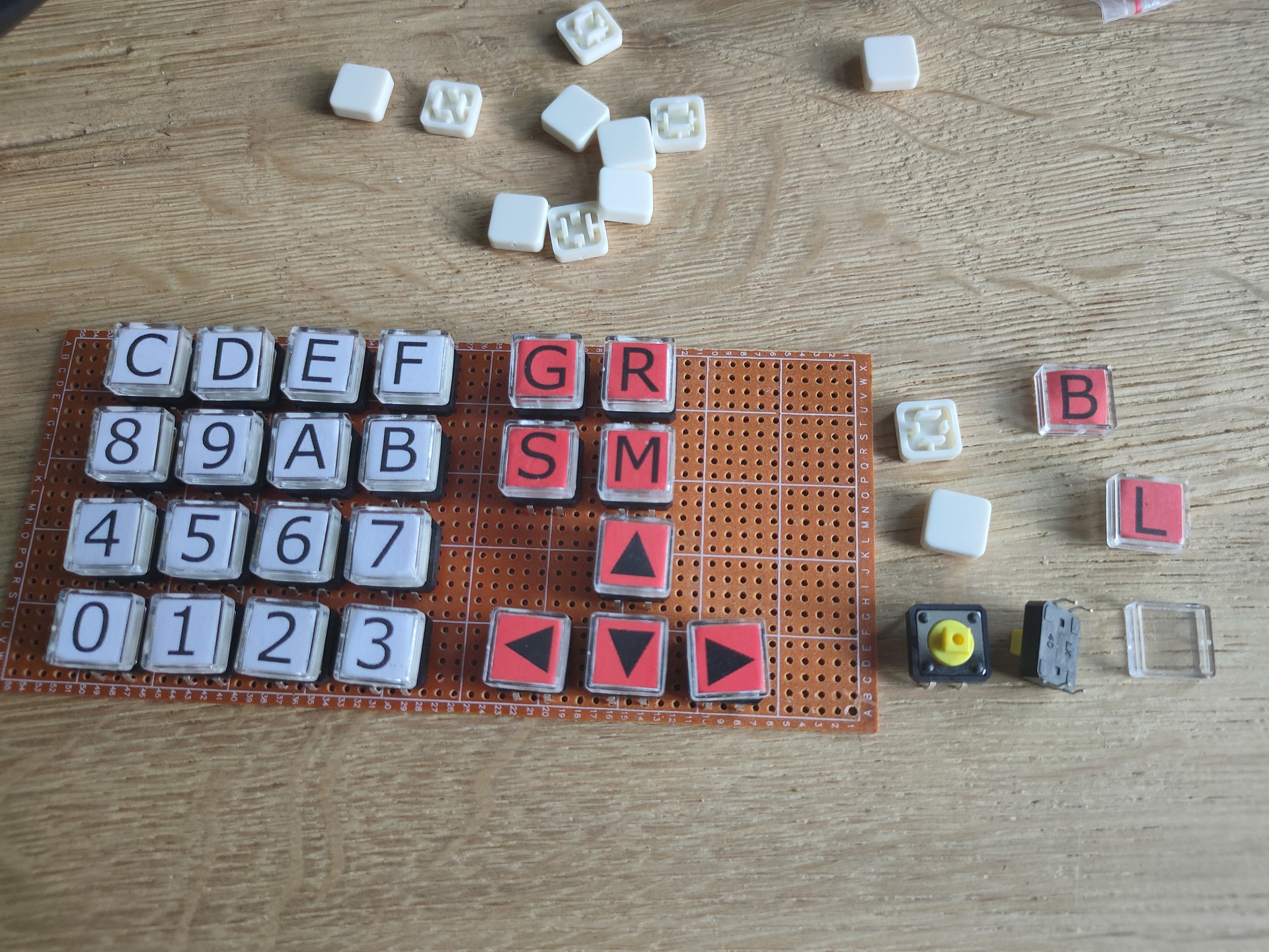
I it just a dual 16key matrix decoder merged together. You can probably use this with raspberries, arduinos etc.
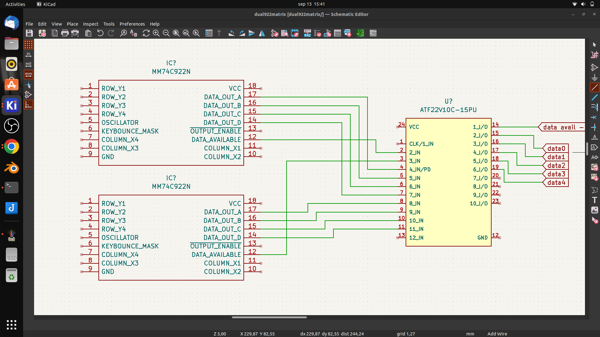
I wanted to use 74C923 but these are nowhere to be found. And even then, the number of keys wil be 20. So i am tying together two 74C922 using some logic in a PLD.
First draft
It wil be something like above. Using the data availabe signal i can combine both 16key matrixes. (In theory .. it is all untested)
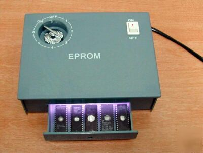
Flashing ROMs .. (eeproms). It used to be a pain in the *$$. Burning took a looong time. But clearing one with UV took .. 20 minutes or so. Using one of these:
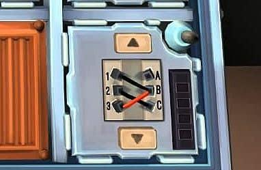
Altered clock module
Changed button press
Dipswitches for more speed control (red .. upper left)
Changed Rom/Ram
Changed addressing
Added RAM
ZIF Socket for ROM
VIC 6522
Fixed clock
Added buttons for interrupt
Display
Display works now
To test: Create Address logic to access display without VIA Can work, but not at high speed clock. Stays behind VIA
To buy: st7920 lcd 128×64
Generic improvements
Rewired most parts, using color codes (Blue data, Yellow Address and so on)
Added leds on data and address bus using ULN2803 darlington arrays
100nF Decoupling capacitors on the power rails
To do’s or ‘have to look into’s’
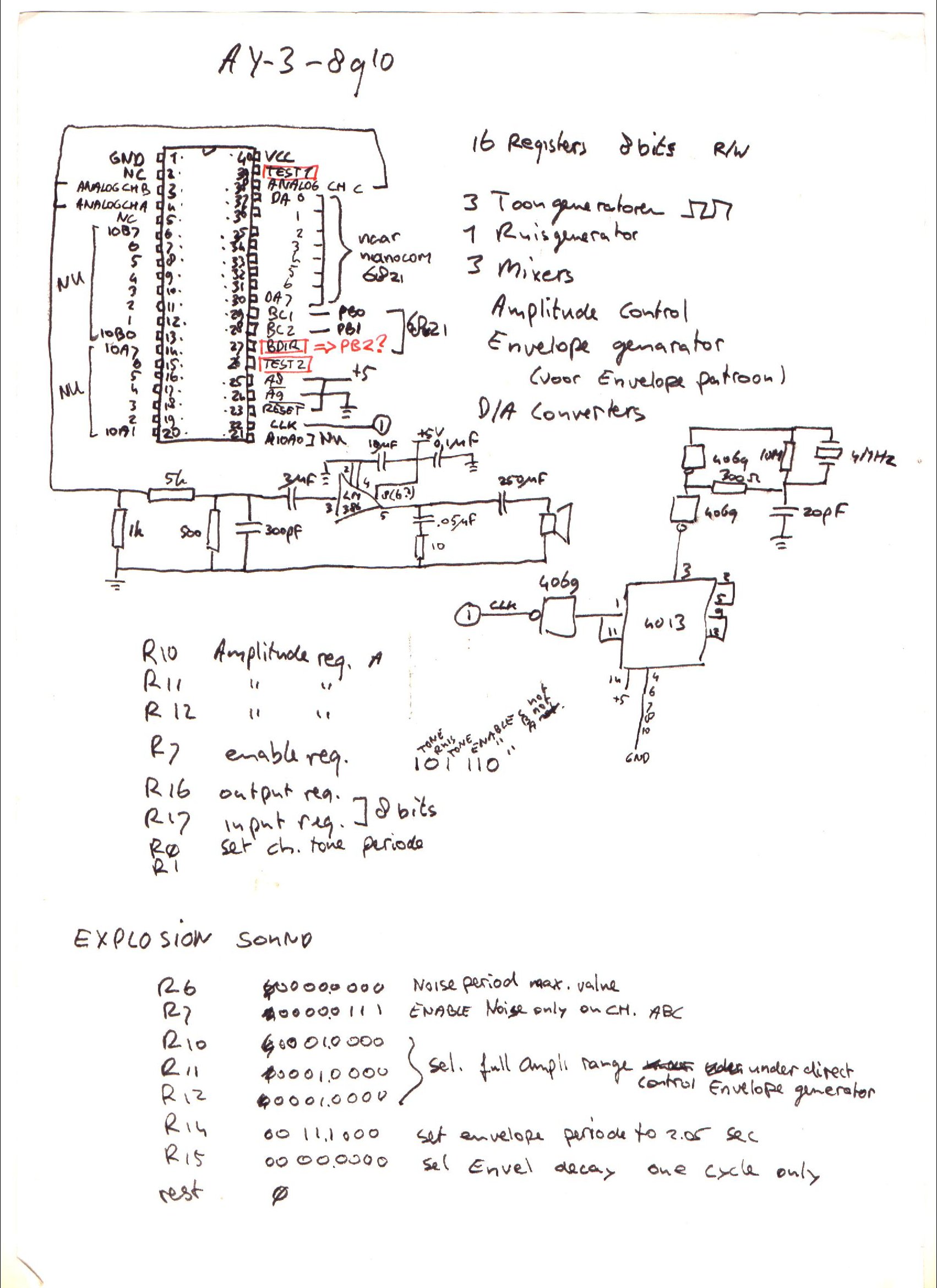
For sound i planned to use a General Instrument AY-3-8910, it is somewhere in my Lab, i know it is. I saved this chip and a SID for my Amiga addon soundcard. Where are my plans for the simple v1 setup? (FOUND IT)
I have to start writing rom functions for display usage. Like JSR $ff00 – Clear screen subroutine .. etc
I’m scraping information from websites, to get started on my clock controller. ATmega328 with ssd1306 display and rotary encoder/dip switches
Notes about the movie: Left side is Arduino IDE monitor reading Addressbus and Databus. (I’m going to try to rewrite this to realtime disassemble) Resetting system. Stepping CPU with manual clock pulses. Start vector being read at $FFFC/$FFFD. Program being run from $8000. Set clock on automatic ( ~ about 150 Hz ) Last opcodes you see a JMP loop 4C 2F 80, that is JMP $802F Display enlarged on video, was not visible on movie i took on mobile. (Wrong angle?)
Breadboard overview
Clock module
Reset module + Crystal
CPU + nmi/int buttons
RAM and ROM
Address decode + Bus divide
Addres/Data bus leds
6522 VIA + Display
2nd via + Buttons
?
(sound board)
TIL: 6502 can run without ram only rom,expect when using JSR … which uses a program stack in RAM
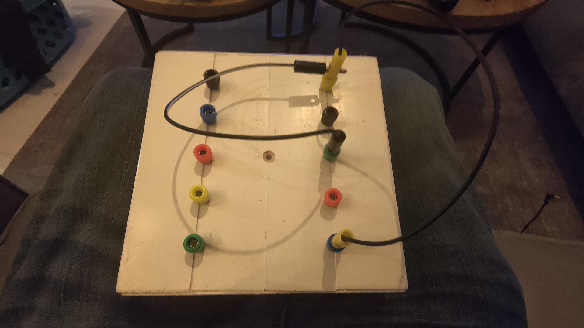
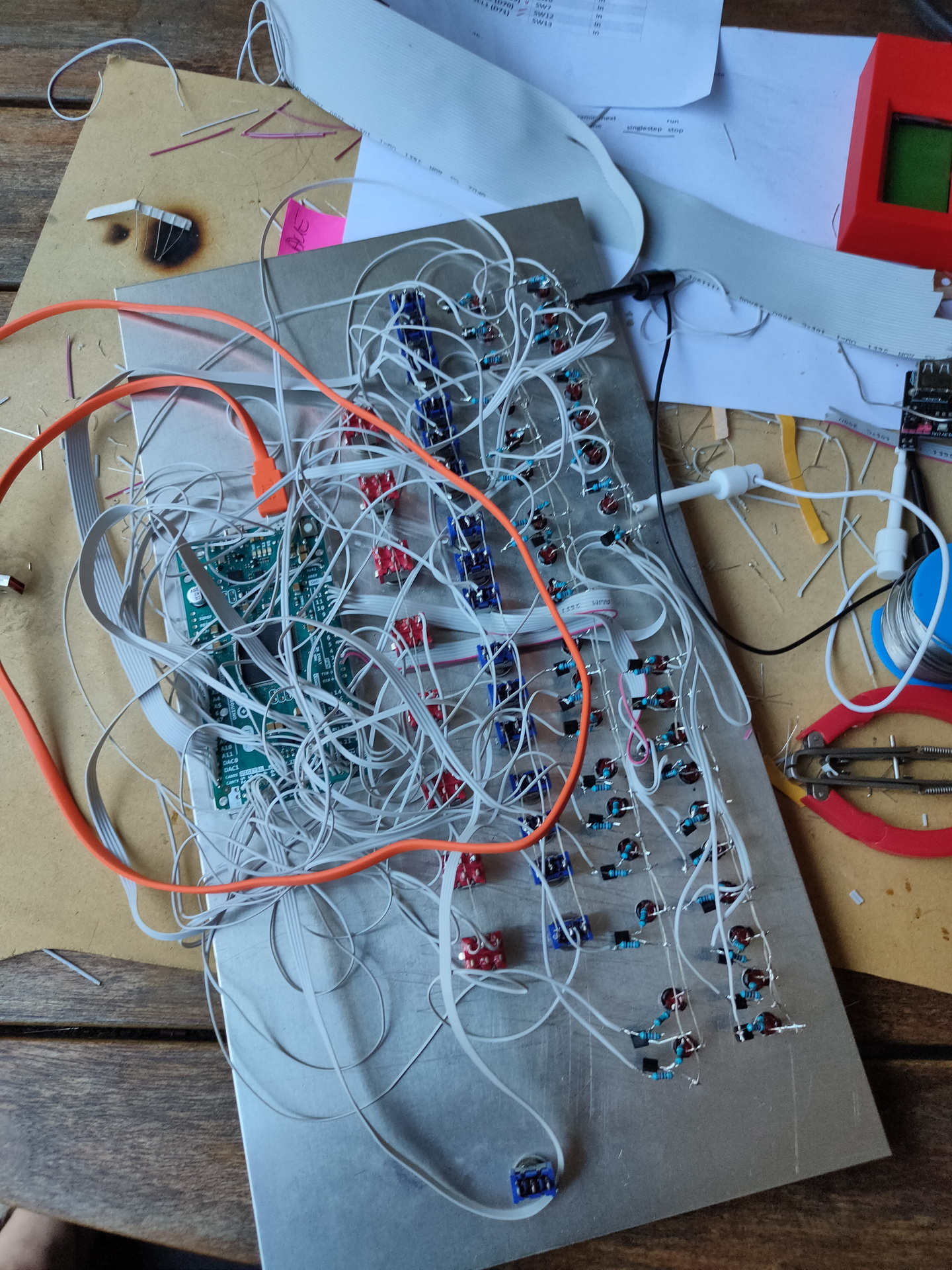
After a whole day soldering yesterday, ending up with a wire mess. Which didn’t work at the end…
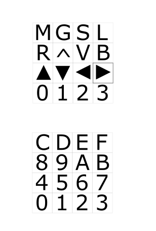
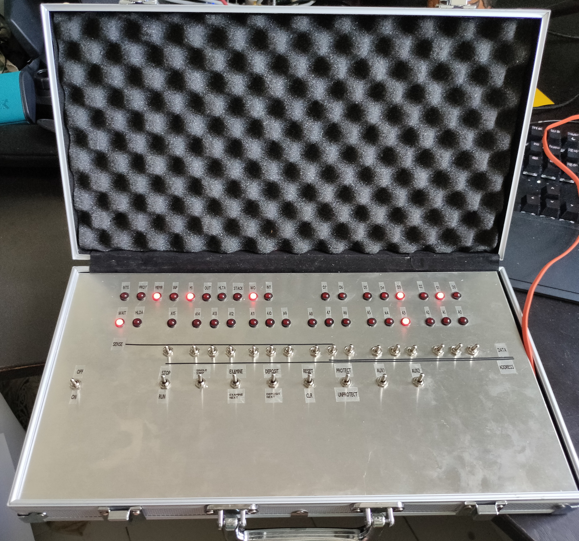
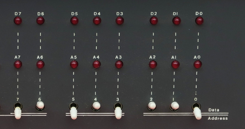
Starting measuring some things, and create some test sketches (led blinky tests) I found out that the main problem was not having the red switches connected to GND. Blue switches where upside down, this was a easy fix. Because these are ON-ON switches, and where already connected to a common line. Then a mixup between D0 and D6 (wires crossed) And it is working! Made some lines and lettering on the frontplate after some playing around.
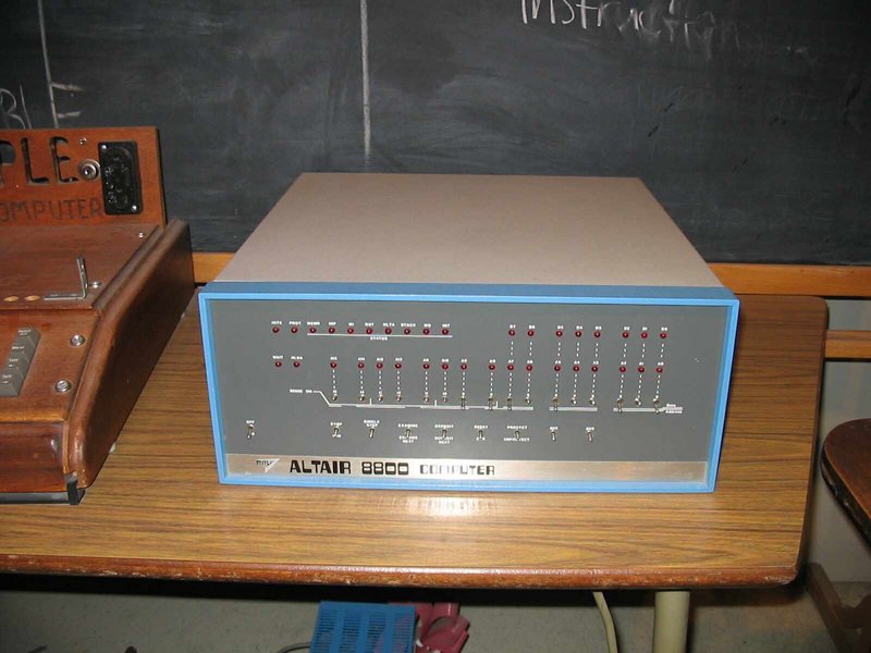
The Altair 8800 is a microcomputer designed in 1974 by MITS and based on the Intel 8080CPU. Interest grew quickly after it was featured on the cover of the January 1975 issue of Popular Electronics and was sold by mail order through advertisements there, in Radio-Electronics, and in other hobbyist magazines.
(picture from wikipedia)
UPDATE: 20220804 – Added Octal sheet
I alway loved the simple setup of this computer. There was no screen and no keyboard. Only later additions to the machine provided these.
One explanation of the Altair name, is that the name was inspired by Star Trek episode “Amok Time“, where the Enterprise crew went to Altair (Six).
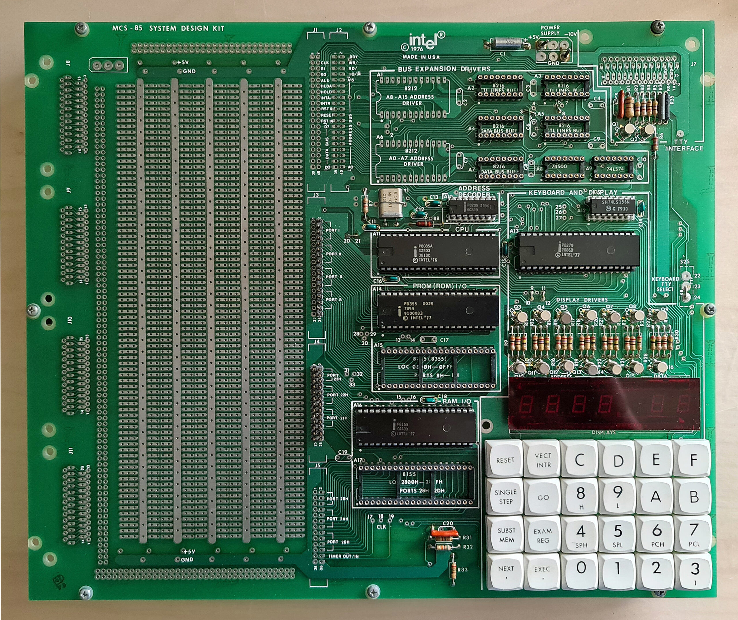
There are only a few differences between the used 8080 CPU and the 8085 CPU of a machine i learned machinecode on.
See : https://www.henriaanstoot.nl/1989/01/01/8085-machinecode-at-school/
So for a really long time i wanted to have a Altair alike machine. There are do it yourself kits for sale. Which look like perfect relica’s and there are virtual machines and emulators. But i wanted to have the feeling of throwing the switches. You can find a emulator here (https://s2js.com/altair/)
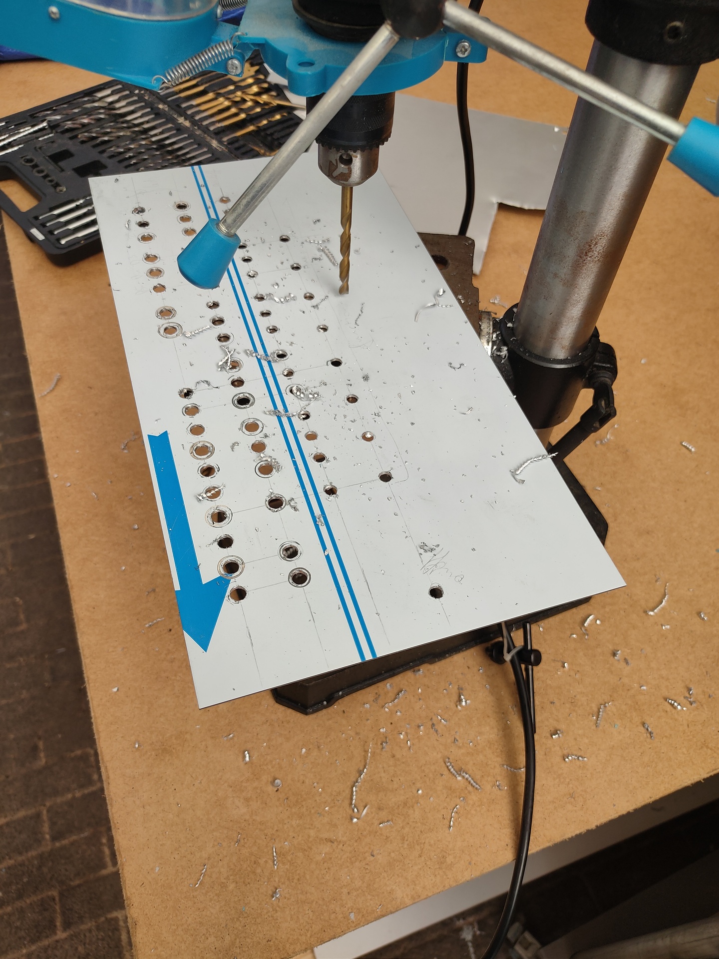
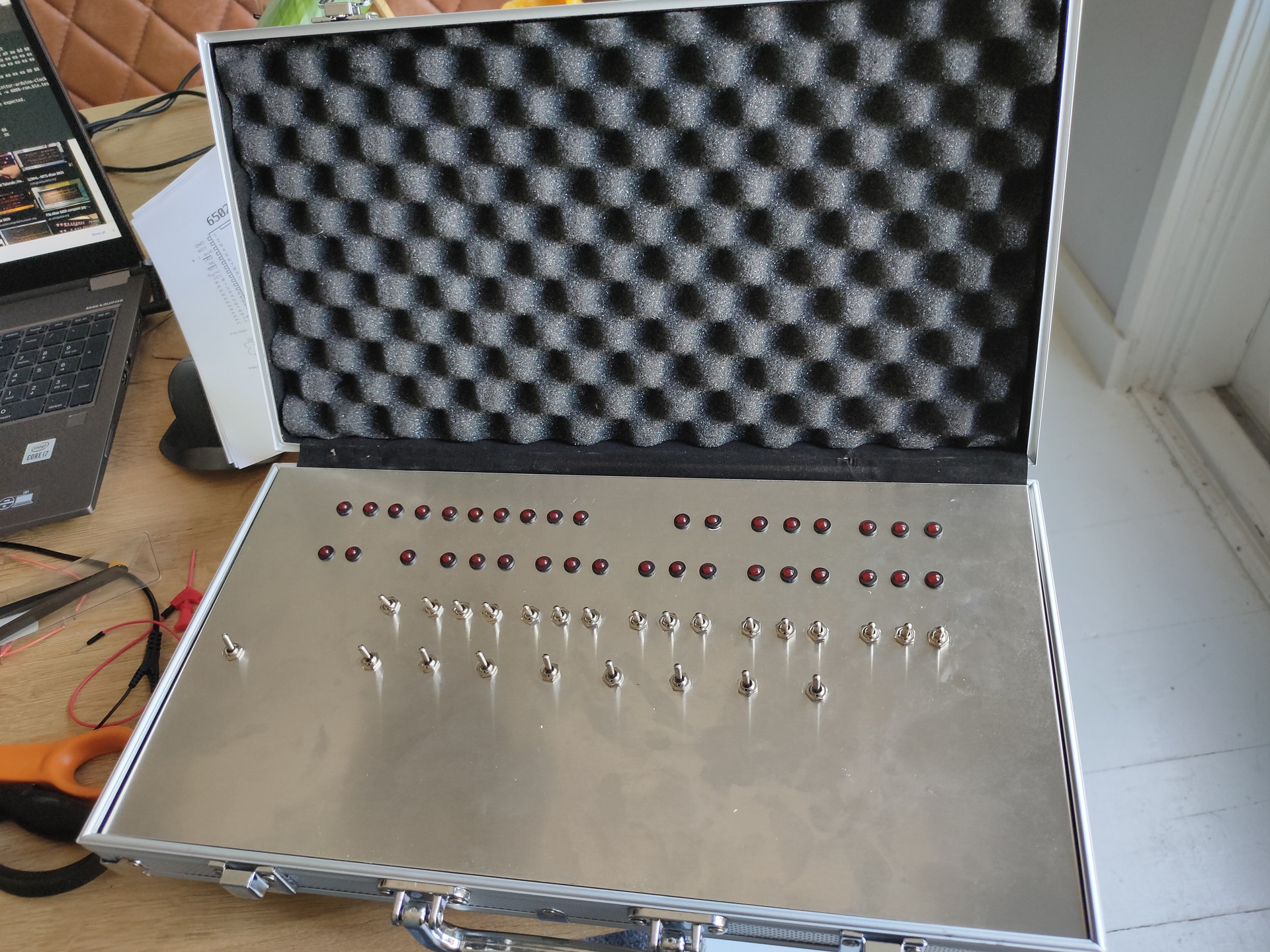
So i bought the components, a poker case which can hold the machine. And started building today.
The backend is a arduino based emulator, but with real leds and switches! (https://create.arduino.cc/projecthub/david-hansel/arduino-altair-8800-simulator-3594a6)
Components and pokercaseDrillingFirst looks
Next to do:
Fix plate into case
Solder a LOT of wires and components!
Shall i get rid off the transitors and use darlington arrays?
Put lettering on the aluminium plate : Functions and Bus information.
Build a power connector in the case
And then … programming 🙂
UPDATE: 20220804 – Added Octal sheet
The Altair is a octal based machine, but i couldn’t find a opcode list in Octal. So i generated one. When entering a MOV D,M instruction for example, you have to enter x 0 1 0 1 0 1 1 0 using the switches Thats 126 in octal but most tables are in hex ( MOV D,M is 56, which is 0101 0110 but not that clear on the switches)
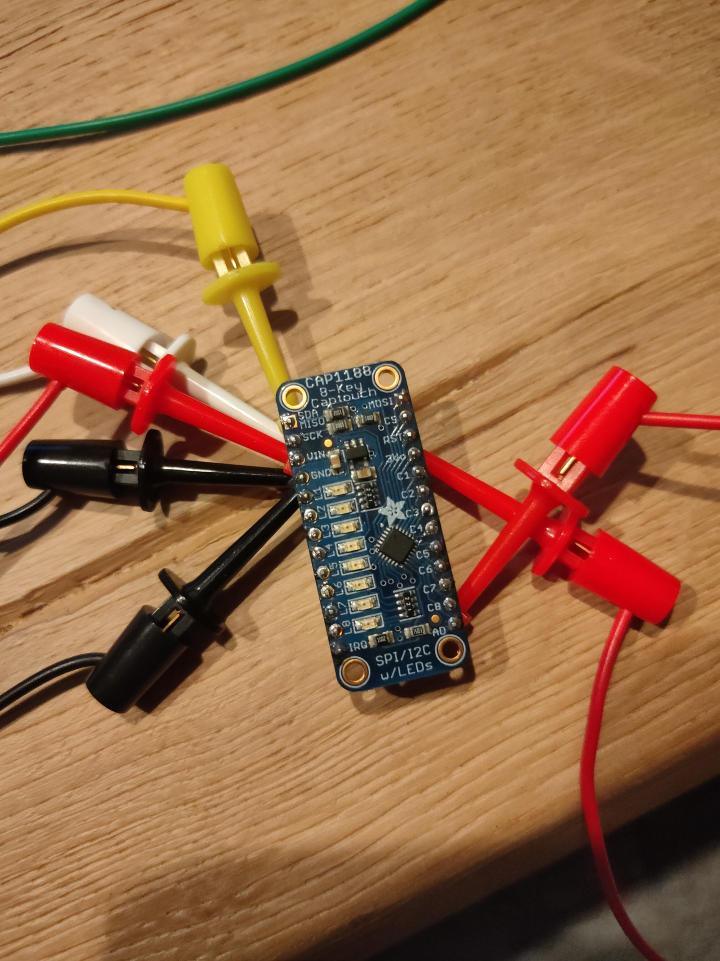
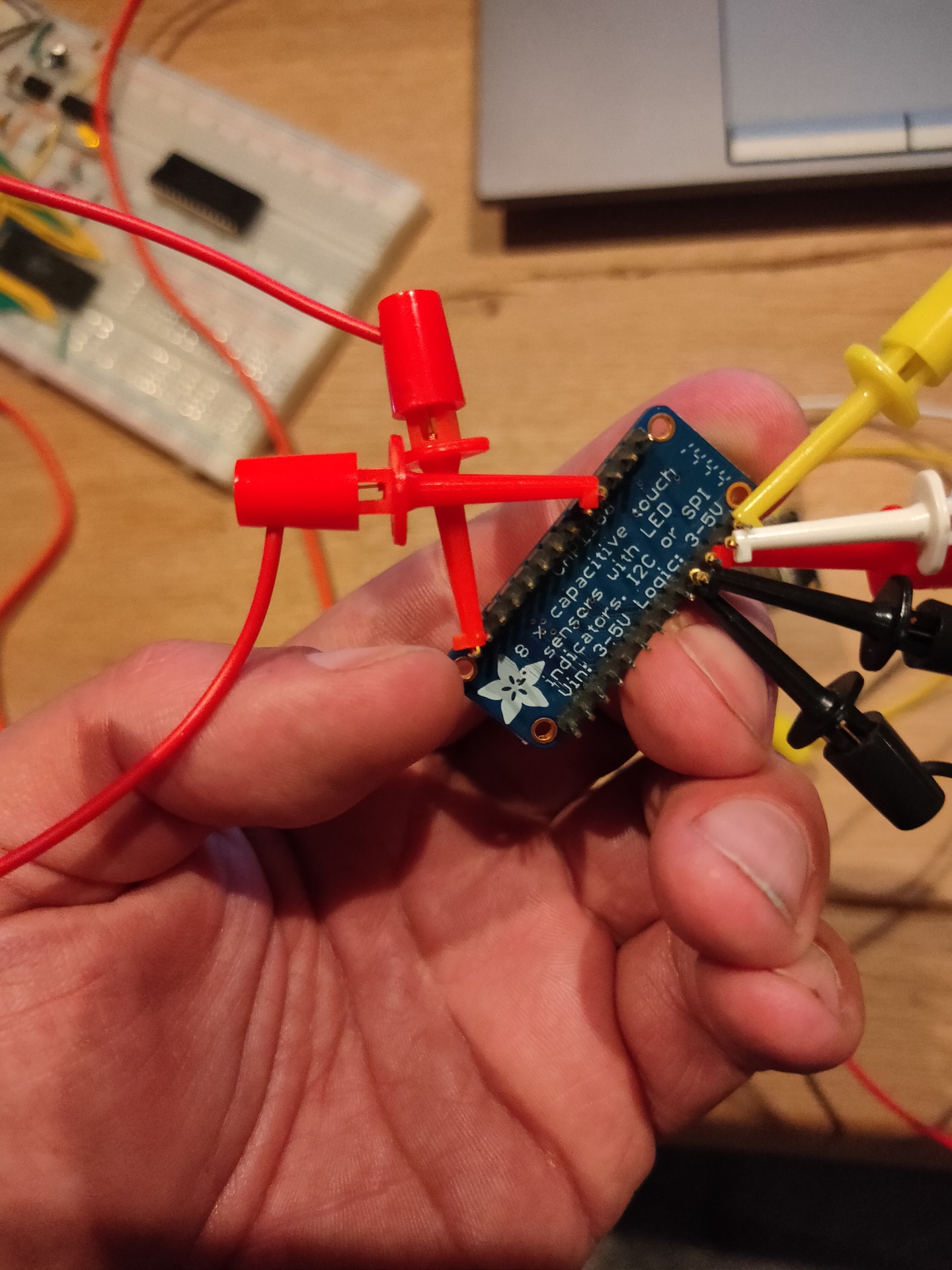
Way back in 2018 i was playing around with i2c and touch.
CAP1188 Multi touch sensor
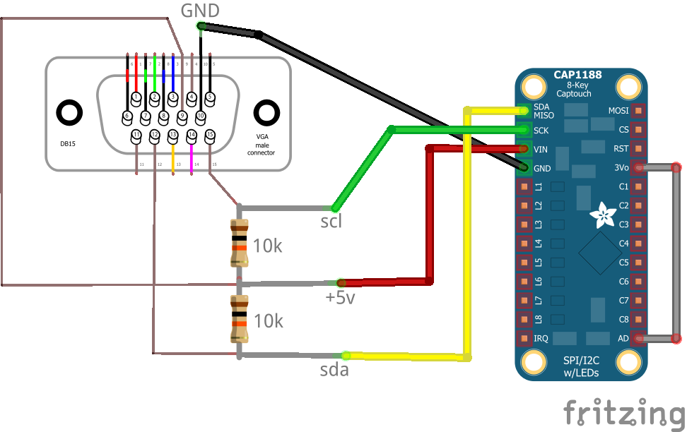
I remembered that VGA was using i2c to get information from monitors like brand/type and connection information.
I managed to access the cap1188 up to my Laptop via VGA.
2018 Schematic i used to abuse vga …
The final python code i used to play with the variables and playing sound i can’t find. But below is the test code
#!/usr/bin/python

# NOTE: i did a address scan, now i have 3v3 connected to AD, so probably the address is 0x28 !!

import smbus

bus = smbus.SMBus(1)    # 0 = /dev/i2c-0 (port I2C0), 1 = /dev/i2c-1 (port I2C1)

DEVICE_ADDRESS = 0x29
DEVICEx = 0x10
DEVICE_REG_MODE1 = 0x00
DEVICE_REG_LEDOUT0 = 0x1d

#Write a single register
bus.write_byte_data(DEVICE_ADDRESS, 0x1f, 0x3F)

#Write an array of registers
#ledout_values = [0xff, 0xff, 0xff, 0xff, 0xff, 0xff]
#bus.write_i2c_block_data(DEVICE_ADDRESS, DEVICE_REG_LEDOUT0, ledout_values)
while True:

        print bus.read_byte_data(DEVICE_ADDRESS,0x10), bus.read_byte_data(DEVICE_ADDRESS,0x11) , bus.read_byte_data(DEVICE_ADDRESS,0x12), bus.read_byte_data(DEVICE_ADDRESS,0x13), bus.read_byte_data(DEVICE_ADDRESS,0x14), bus.read_byte_dat
a(DEVICE_ADDRESS,0x15), bus.read_byte_data(DEVICE_ADDRESS,0x16), bus.read_byte_data(DEVICE_ADDRESS,0x17)
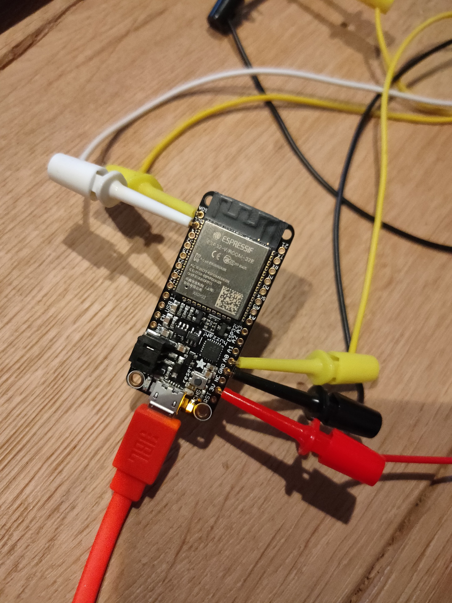
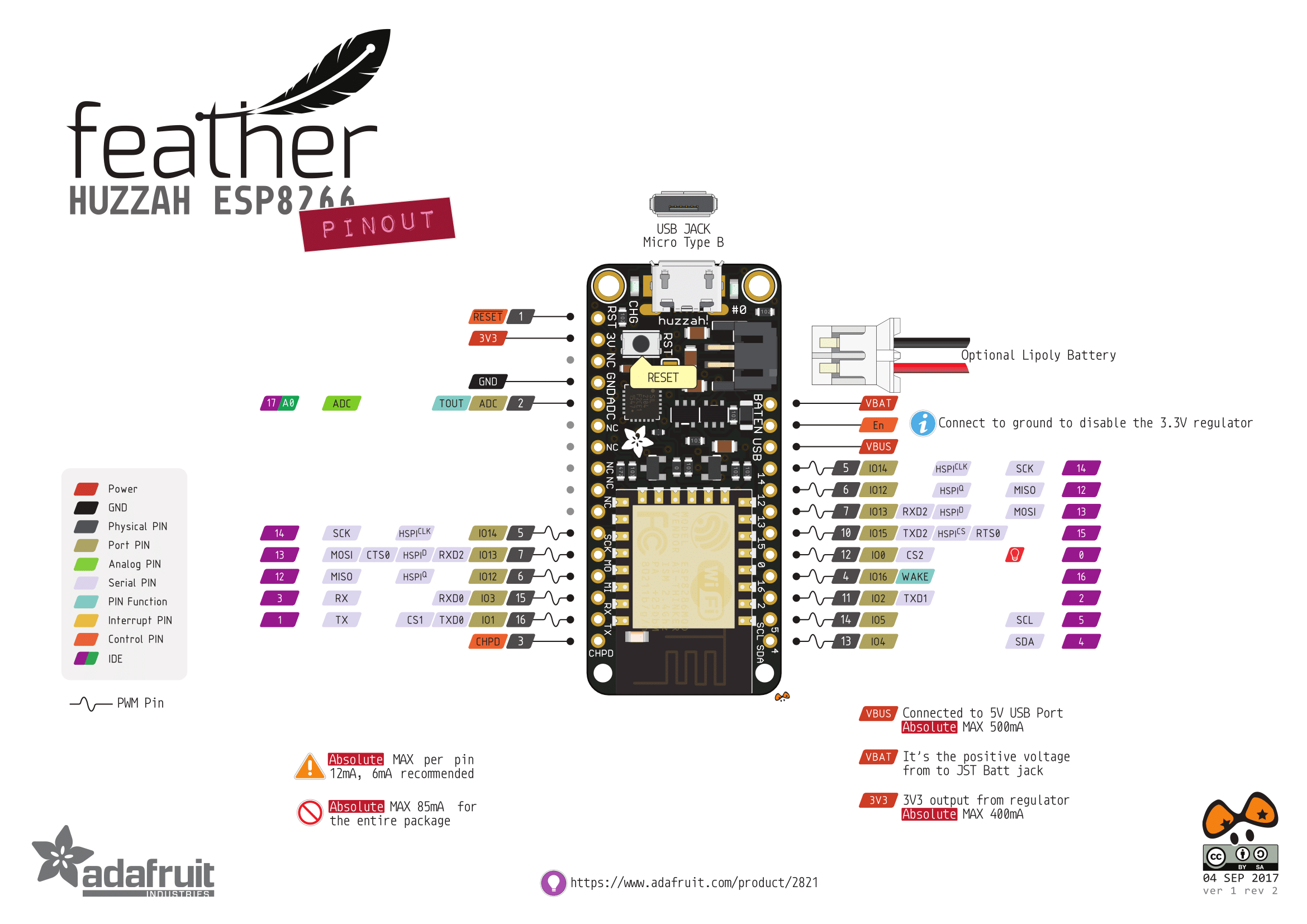
Today i connected the cap1188 to a ESP32 and a piezo buzzer.
ESP FuzzahBuzzerCAP1188CAP1188
/*** Based on below library ***/
/*** Changed pins and added sound ***/

/***************************************************
  This is a library for the CAP1188 I2C/SPI 8-chan Capacitive Sensor

  Designed specifically to work with the CAP1188 sensor from Adafruit
  ----> https://www.adafruit.com/products/1602

  These sensors use I2C/SPI to communicate, 2+ pins are required to
  interface
  Adafruit invests time and resources providing this open source code,
  please support Adafruit and open-source hardware by purchasing
  products from Adafruit!

  Written by Limor Fried/Ladyada for Adafruit Industries.
  BSD license, all text above must be included in any redistribution
 ****************************************************/

#include <Wire.h>
#include <SPI.h>
#include <Adafruit_CAP1188.h>

const int TONE_OUTPUT_PIN = 26;
const int TONE_PWM_CHANNEL = 0;
int freq = 0;


// Reset Pin is used for I2C or SPI
#define CAP1188_RESET  9

// CS pin is used for software or hardware SPI
#define CAP1188_CS  10

// These are defined for software SPI, for hardware SPI, check your
// board's SPI pins in the Arduino documentation
#define CAP1188_MOSI  11
#define CAP1188_MISO  12
#define CAP1188_CLK  13

// For I2C, connect SDA to your Arduino's SDA pin, SCL to SCL pin
// On UNO/Duemilanove/etc, SDA == Analog 4, SCL == Analog 5
// On Leonardo/Micro, SDA == Digital 2, SCL == Digital 3
// On Mega/ADK/Due, SDA == Digital 20, SCL == Digital 21

// Use I2C, no reset pin!
Adafruit_CAP1188 cap = Adafruit_CAP1188();

// Or...Use I2C, with reset pin
//Adafruit_CAP1188 cap = Adafruit_CAP1188(CAP1188_RESET);

// Or... Hardware SPI, CS pin & reset pin
// Adafruit_CAP1188 cap = Adafruit_CAP1188(CAP1188_CS, CAP1188_RESET);

// Or.. Software SPI: clock, miso, mosi, cs, reset
//Adafruit_CAP1188 cap = Adafruit_CAP1188(CAP1188_CLK, CAP1188_MISO, CAP1188_MOSI, CAP1188_CS, CAP1188_RESET);

void setup() {
  Serial.begin(9600);
  Serial.println("CAP1188 test!");
  ledcAttachPin(TONE_OUTPUT_PIN, TONE_PWM_CHANNEL);


  // Initialize the sensor, if using i2c you can pass in the i2c address
  if (!cap.begin(0x28)){
  //if (!cap.begin()) {
    Serial.println("CAP1188 not found");
    while (1);
  }
  Serial.println("CAP1188 found!");
}

void loop() {
  uint8_t touched = cap.touched();

  if (touched == 0) {
    // No touch detected
    return;
  }

  for (uint8_t i=0; i<8; i++) {
    if (touched & (1 << i)) {
      Serial.print(touched); Serial.print("\t");
      freq = (i * 100);
      ledcWriteTone(TONE_PWM_CHANNEL, freq);
      delay(100);
    }
  }

  Serial.println();
  delay(50);
}
Finding the right pins or above pinout was the hardest part. The sketch reads the pins binary so value 129 is first and last bit.
Now i have to get the sound sounding a little better and add frequencies and fingersettings to the sketch to get a minimal electronic bagpipe. (V3 it is .. )
To be continued ..
"If something is worth doing, it's worth overdoing."