I’ve took it offline, maybe someone wants the source code and database.
It was much fun, time to move on.
UPDATE: 20230228 – It is online again.
(I’ve got some mails and mentions in music forums)
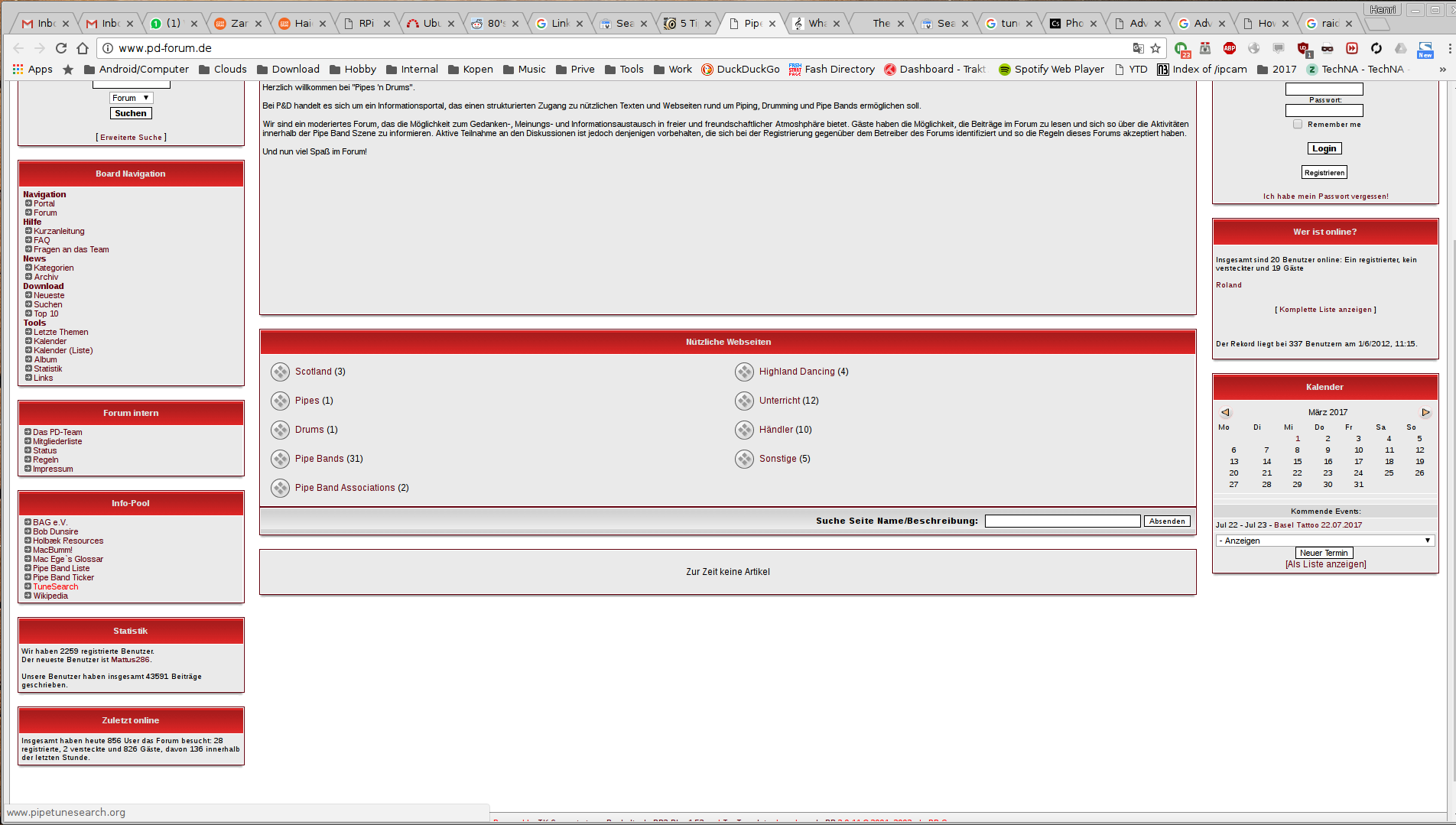
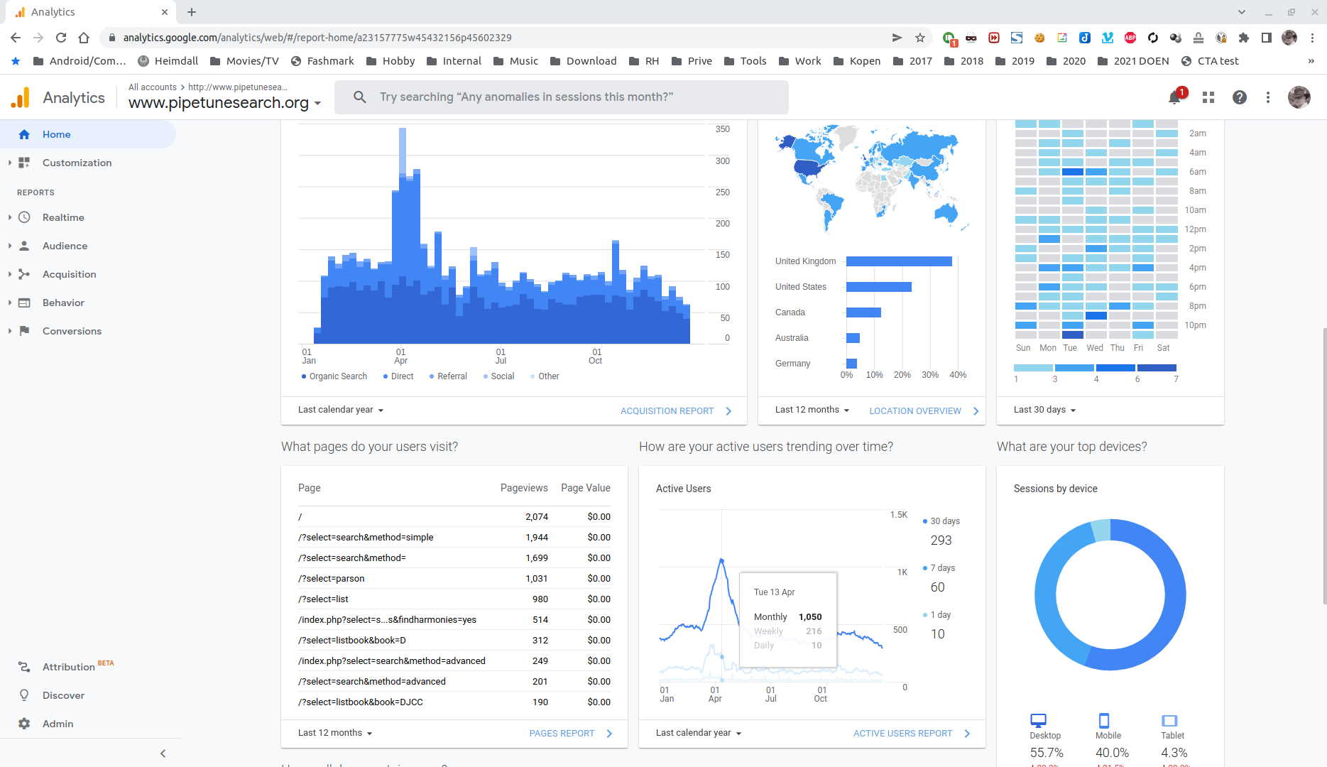
https://pipetunesearch.henriaanstoot.nl/
At least i’ve got some nice reactions
I’ve create my own bww/bwm to parsons code convertor.
Rest of the website is php, mysql … first one started in 2001 using php3, until php7.
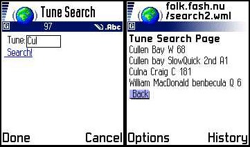
PARSONS CODE: OMG, you don’t know how long I have been waiting for a search engine to find tunes in my head. I thought about creating some kind of dictionary based on theme notes, or searching through bww files for sequences. What a thrill to find your site. I just hum a tune, use the up, down, repeat letters and… like magic the title is found. You are a genius. I will never be stumped for a title again. Thanks so much, John
Other successes i’ve heard of are: 2 Youtube movies being identified, a nameless bww file and mp3’s
Mail from Dave:

Hiya

My name is Dave Mason. I put a few tunes together a few years ago called "Tummle Yer Wilkies" which, I see, gets mention on your website. However, I see that you're not sure where people can access the tunes.

Well, the book is free to download from https://sites.google.com/site/tummleyerwilkies/home and I hope to have volume 2, "Tummle Yer Wilkies Too!" uploaded in the near future.

Cheers
Dave Mason

Geneva, Switzerland.

NEW - Palm version by Andreas Joebges (updated)
Added stuff changed software
Added parts in booklist and search.
Additions to www.drumscoresearch.org
Many additions by: Chris MacKnight
Palm version by Andreas Joebges
Added index send by : Henning
sat 14 feb: Installed DB on macbumm's site
sun 15 feb: Made some changes, limit search and layout
            Removed own collections from DB
            Expanded statspage with jig/hornp/march/etc.
mon 16 feb: Imported College of Piping index i got from Ralf .. (thanks!)
            Imported Irish Tunes for Warpipe
            Added Log, Fixed Members Login for edit purposes
tue 17 feb: Layout, testing new functions
wed 18 feb: Imported Bagpipe Music - John MacFadyen
thu 19 feb: Uploaded some Book Covers,
            programmed a export-to-xls function, so you can use the
            DB data yourself (bottom of booklist pages)
            Imported Gordon Highlanders Vol 1
sat 21 feb: Fixed m?c and l*ken search
            Imported Gordon Highlanders Vol 2
            Added AKA search
            Old search request stays in search field
            Added some covers
            code cleanup
mon 23 feb: Fixed bookcover popup
            Imported Mark Saul Vol I
            Uploaded Mark Saul Cover II and changed faulty cover other Vol
            Bookinfo added ISBN, Price, etc.  Suggestion i got by Email
            Uploaded Queens Own Highlanders The Pipers Day
            Imported Seaforth Highlanders - Standard Settings
thu 26 feb: DB cleanup
            Added Code
            Imported Donald MacLeod vol 1 2 and 4
fri 27 feb: 1st editor assigned - Henny Barnhoorn
sat 28 feb: Imported Vol 5 and 6 Donald MacLeod
sun 29 feb: CD Information added
            2nd editor - Coline Gerritsen
mon 01 feb: Added CDs .. Thanks Coline
            Gordon Highlanders Book 1 checked/added/etc. by Henny .. thanks
            CD displaying code changed
            Imported Robert Mathieson Book 4  (now over 4000 tunes in DB!)
fri 05 mar: Added CDs
            Altered ShowCD Code
sun 07 mar: Imported some books (NOW 50!)
            Henny Completed reediting Gordon Highlanders Vol2
            Add MP3 clip code in cdinfo
mon 08 mar: Imported book
            Fixed image caching for faulty browsers
            Search finds composers also
            Fixed Menu structure
            Added Templates
tue 09 mar: Added link under advanced search - find ALL harmonies. :)
wed 10 mar: Added book with cover + MP3 sample
thu 11 mar: Imported Piob. CD
            Added edit icon help
fri 12 mar: Find tunes on CD in beta test .. :)
            (click search -> advanced .. enter a keyword, mark the media
            checkbox and click search .. CDs found at bottom of page .. :)
sat 13 mar: Imported another filled-in cd-template :)
            Added some covers
wed 17 mar: Added 15 Piobaireachd Society Volumes
sat 20 mar: Added 3 CD's
tue 23 mar: Added several books (5166 tunes now!) Thanks John
thu 25 mar: Changed code, checked book, imported book
tue 30 mar: Uploaded covers, edited book (Murray Blairs) and added books
till
tue 06 apr: Uploaded Covers, Added books, Changed code
till
sat 17 apr: Imported some books, added parts to export-excell
            (will be in search later)
            Henny checked/edited some books
tue 20 apr: Imported books, testing query caching for speed improvement.
            (yes getting kindda large .. this thingy)
thu 22 apr: 100! BOOKs!
--missing log--
Added book, covers e.t.c.
sun 11 jul: Added Battlefield Book (thanx Markus)
mon 11 jan: Added 2 books (thanx again Markus)
- 159 Books
- 9868 Tunes
- 1047 Air’s
- 1315 Jigs
- 638 Hornpipes
- 3352 Marches
- 489 Piob’s
- 1586 Reels
- 844 Strathspeys