I was afraid to start this myself, SMD is on another level for me. But my good friend Marco said … No problem!
So I ordered components online, which was not easy. Selecting the correct parts, sizes and options.
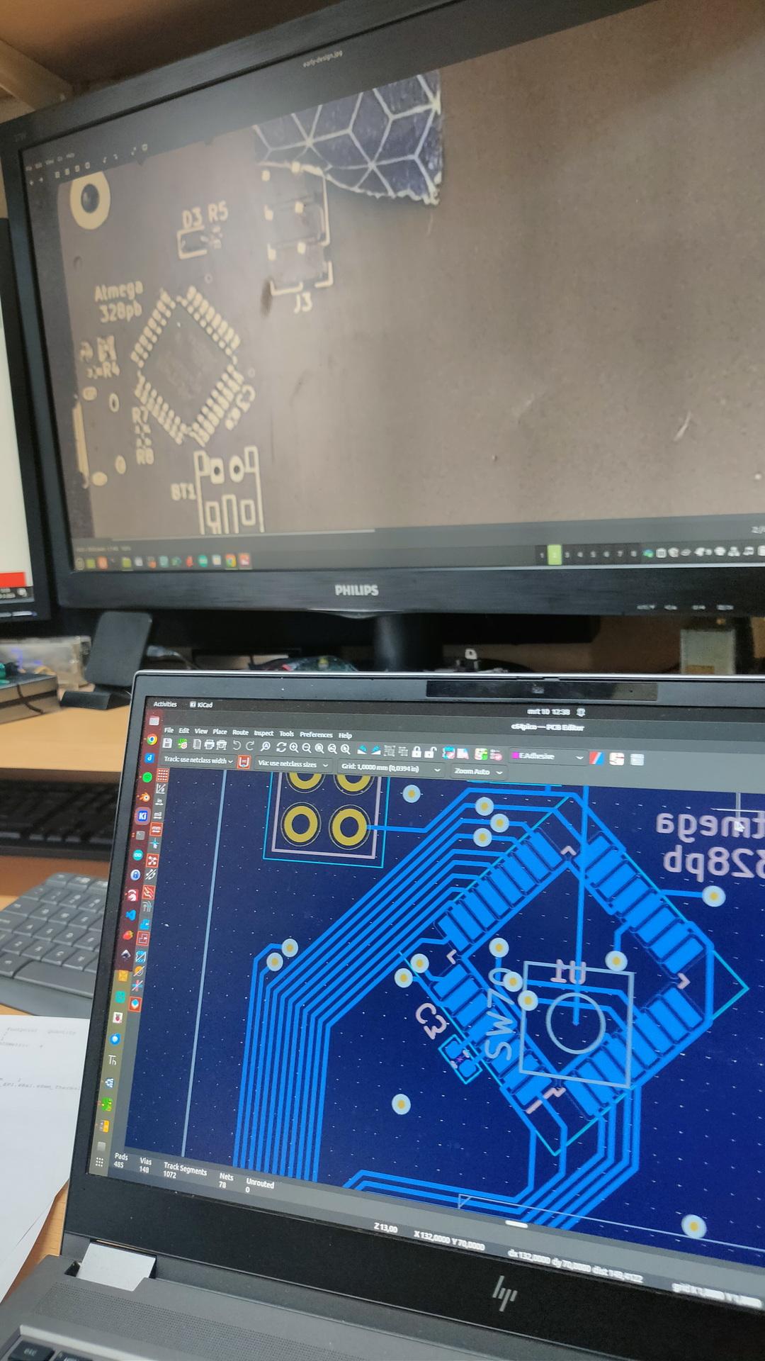
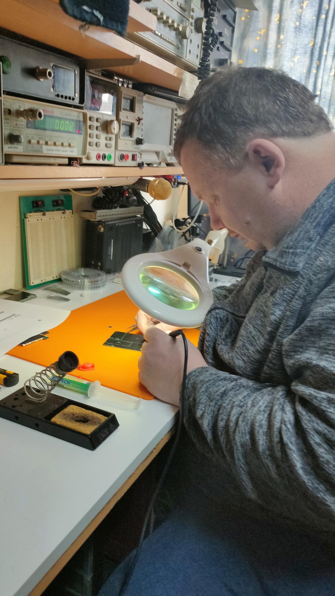
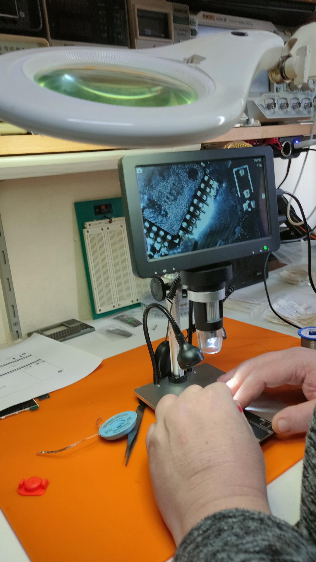
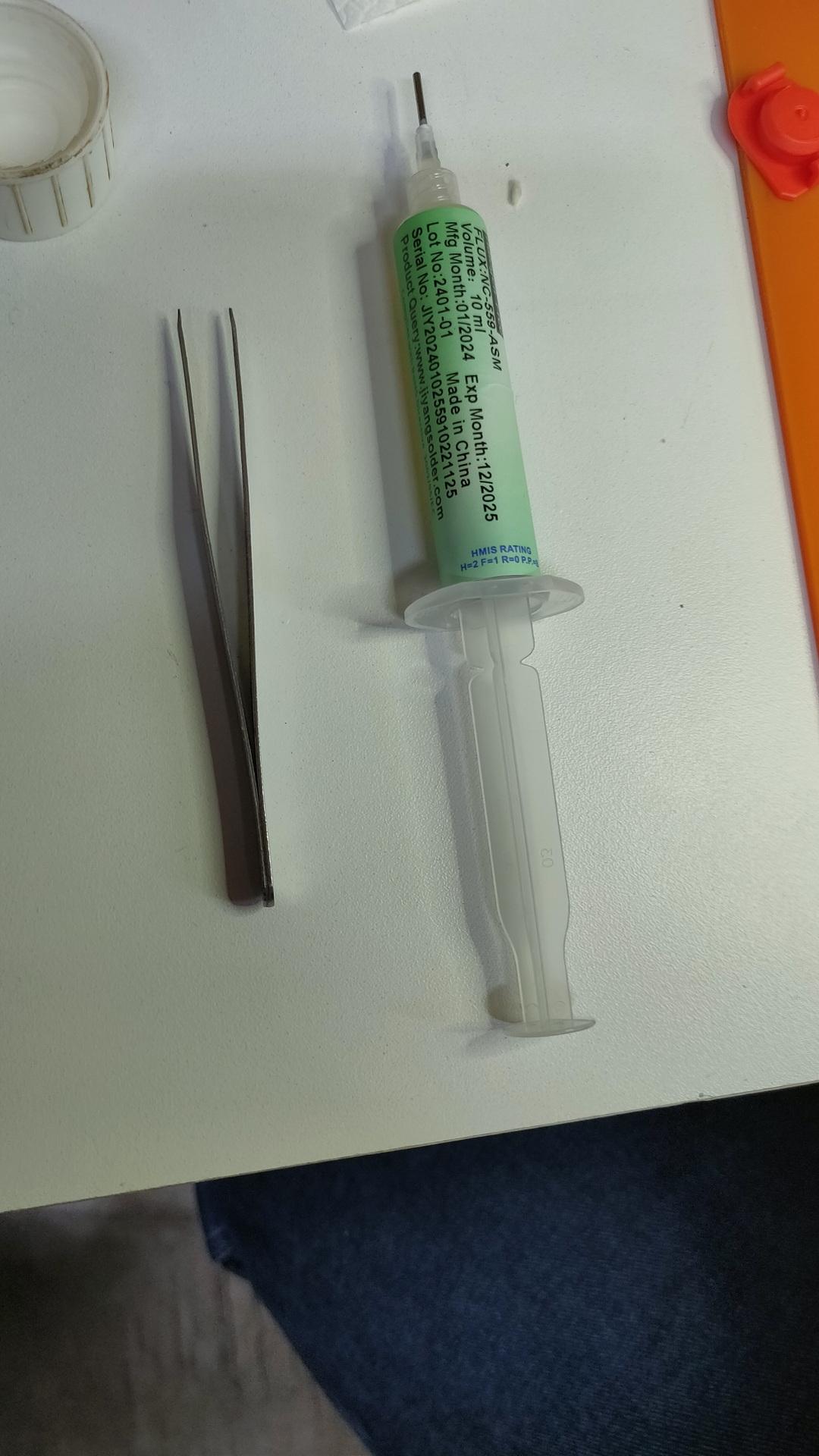
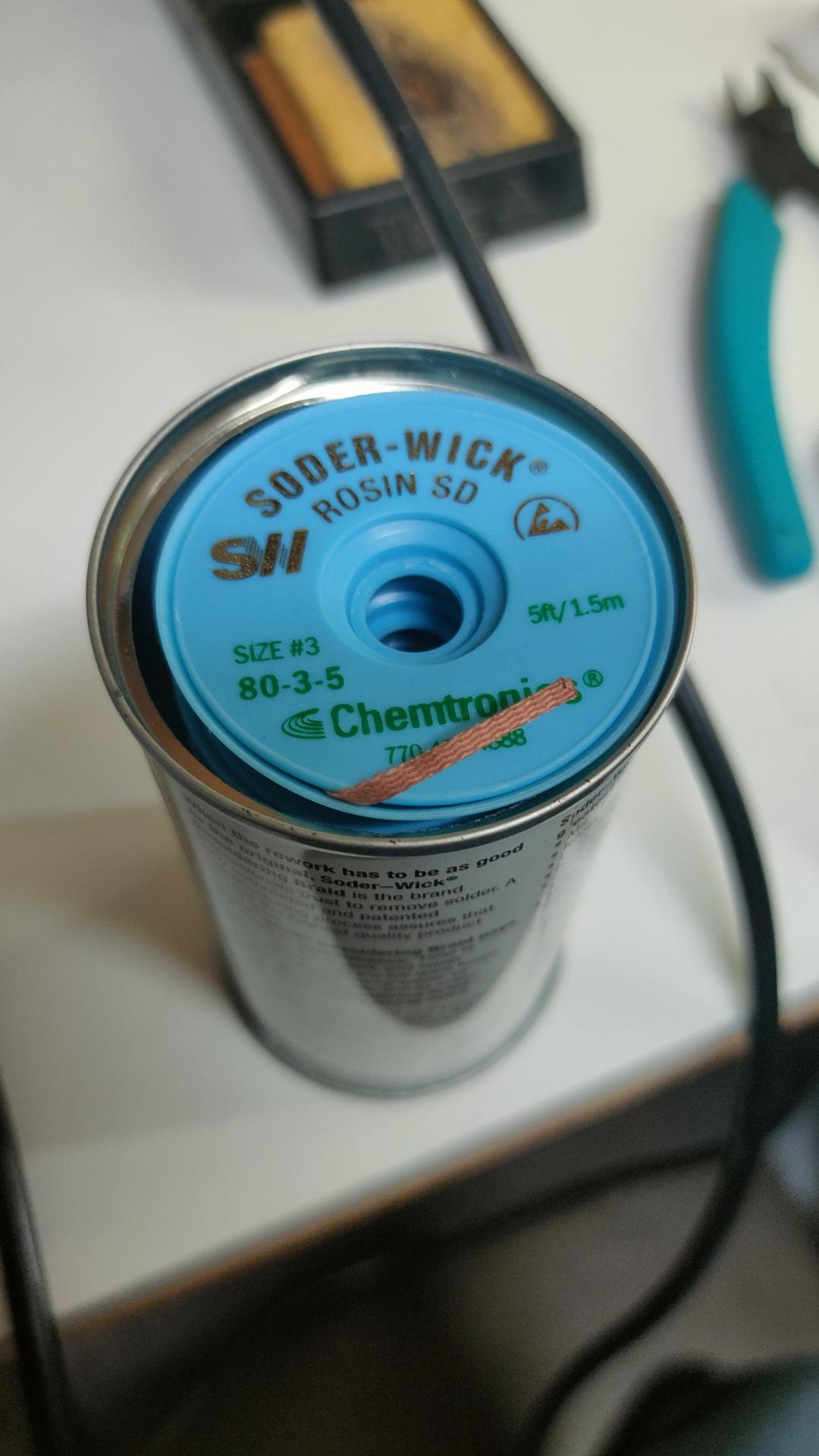
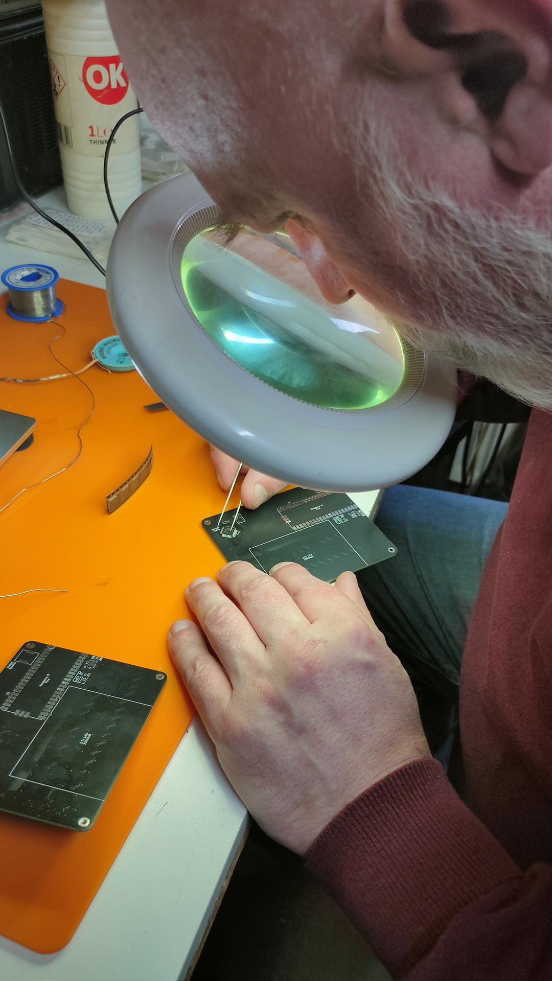
Finding orientations of the componentsThe master at work, he has always been our soldering master (see GPC)Using a microscopeFluxWickI have to do one myself
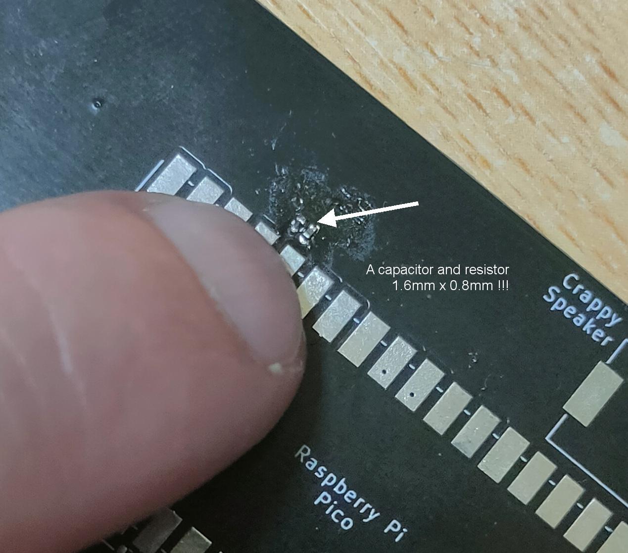
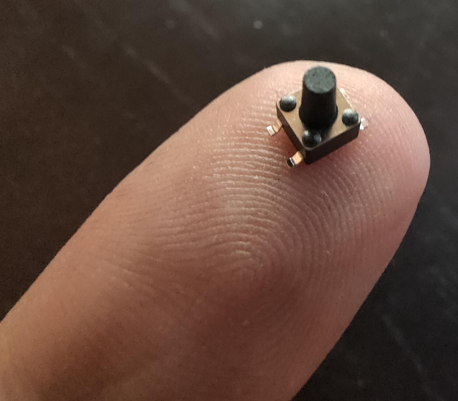
These things are really really small
1.6mm x 0.8mm40 connections / 20mm !
Using tweezers to place the components was even difficult. The slippery tiny bastard got catapulted everywhere. (Or got stuck on fingers, soldering iron and alike) Many small components got lost into the 7th dimension. Never to be found again.
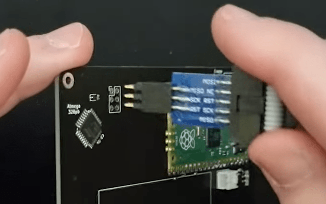
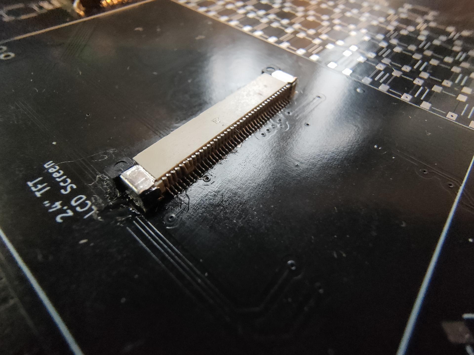
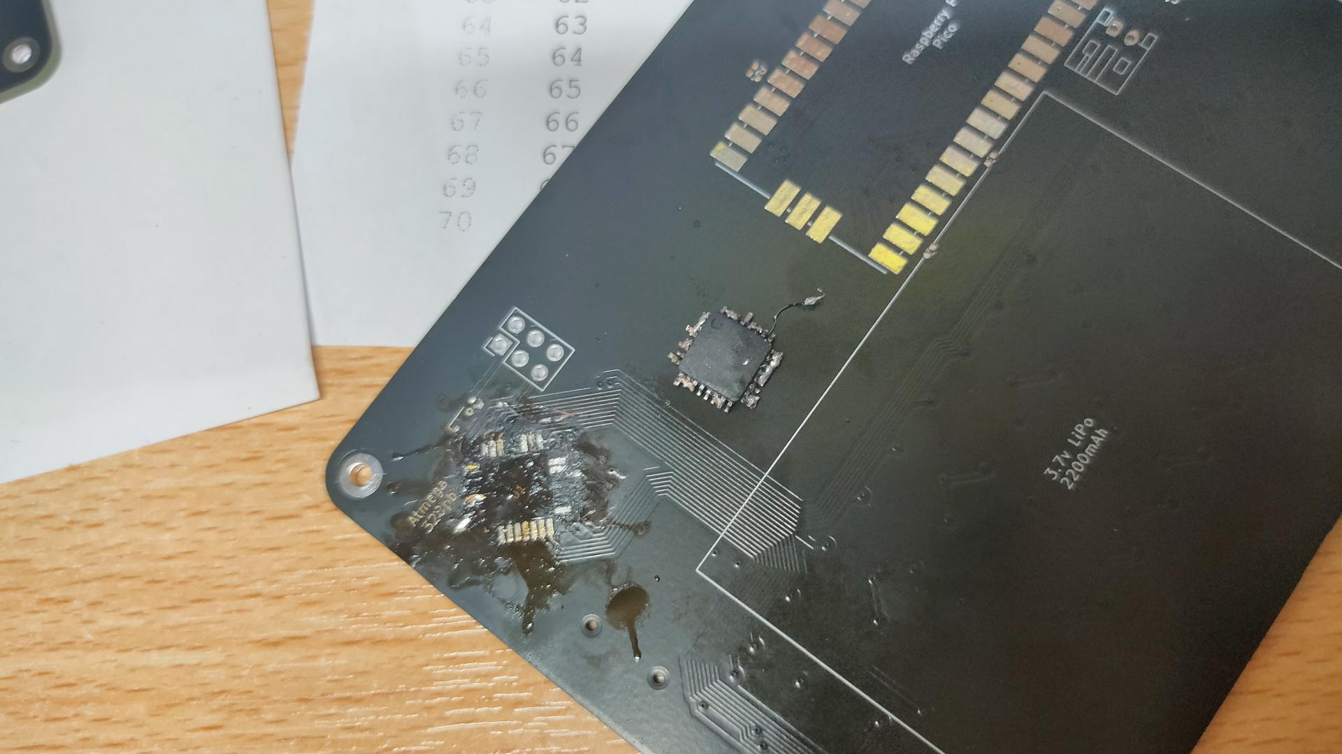
Awesome to work on this together, but Marco said that I have to try it myself. Welllll, I got 3/4 of the ATmega328PB-A perfectly soldered, then I notished that it was crooked. Desoldering was a mess, and I heated the PCB TOO much with the heatgun.
My messed-up PCB, and f*cked-up IC. Leave it to the professionals.
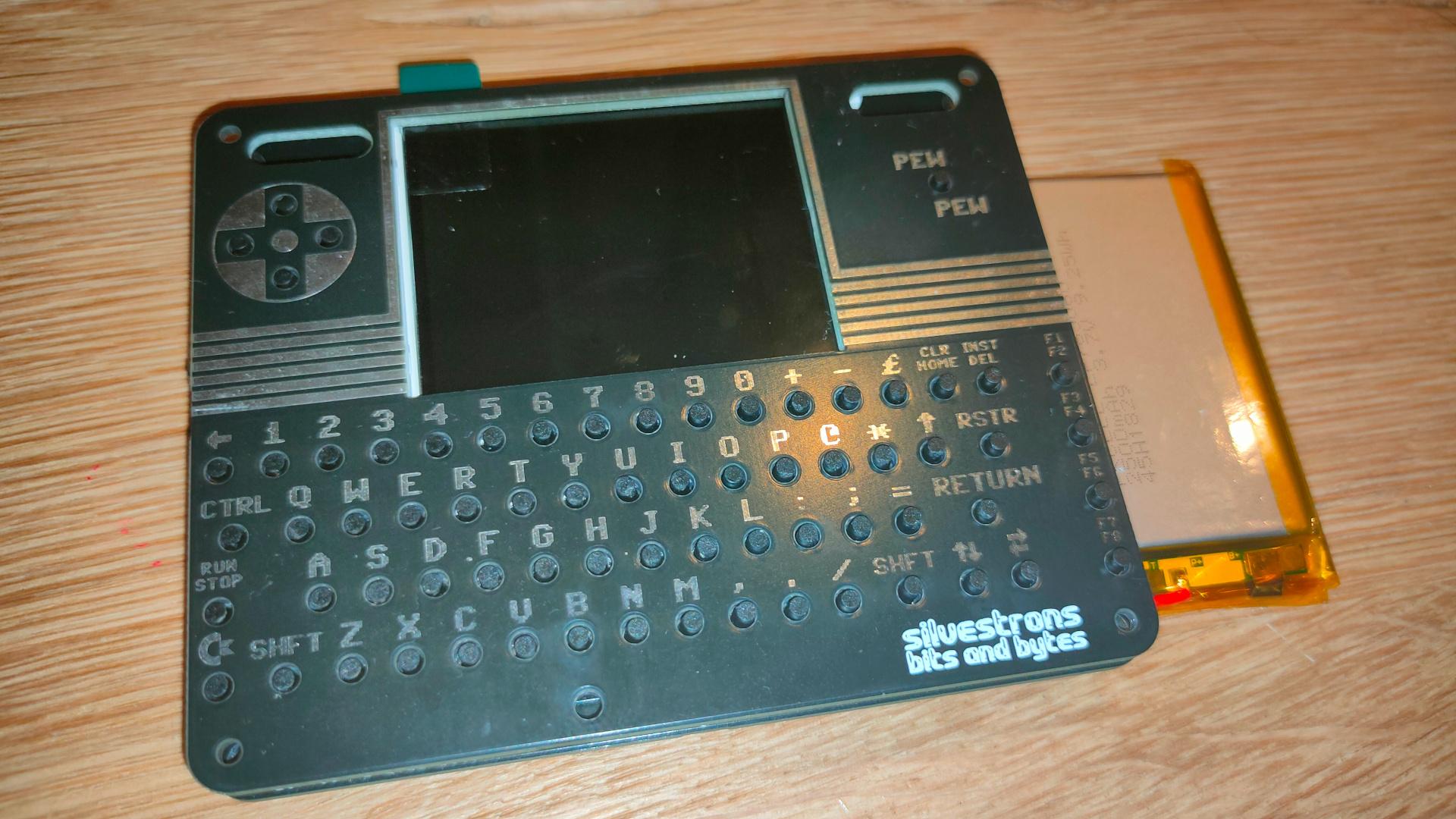
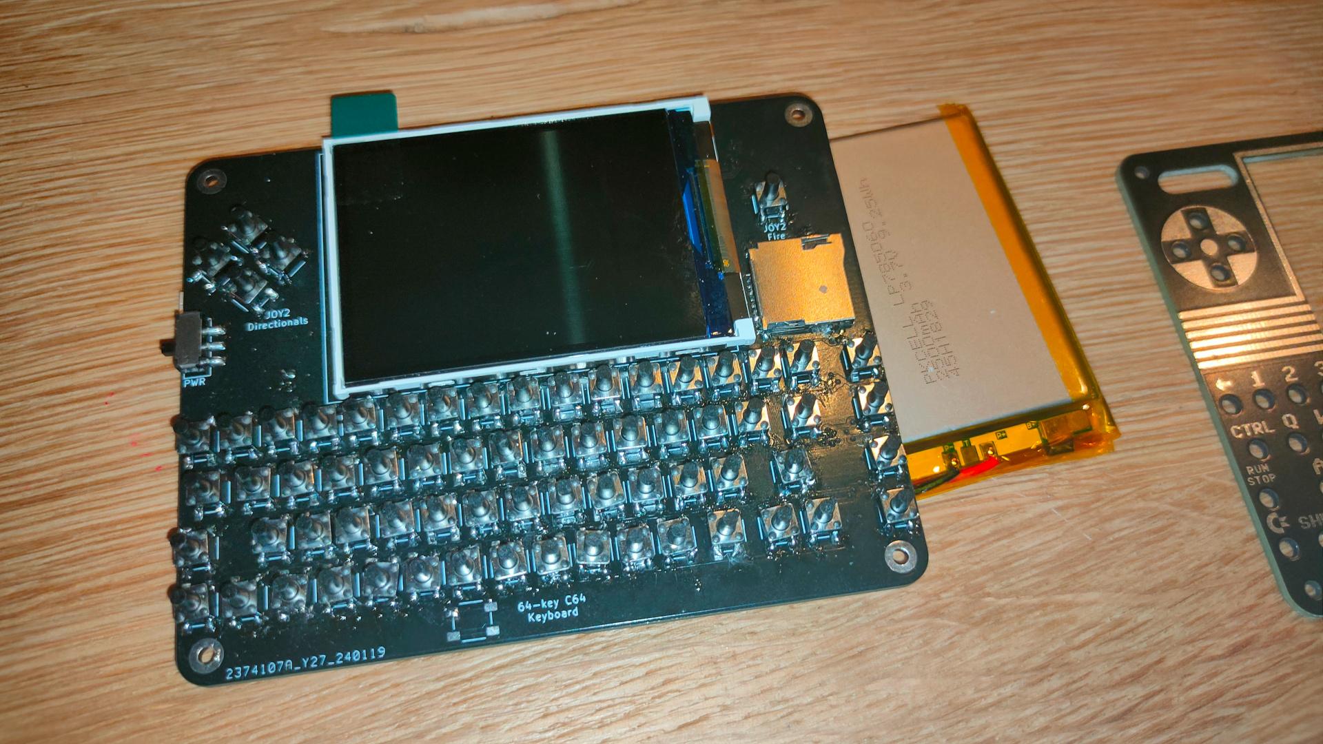
Next step for me is soldering the 75 mini buttons!
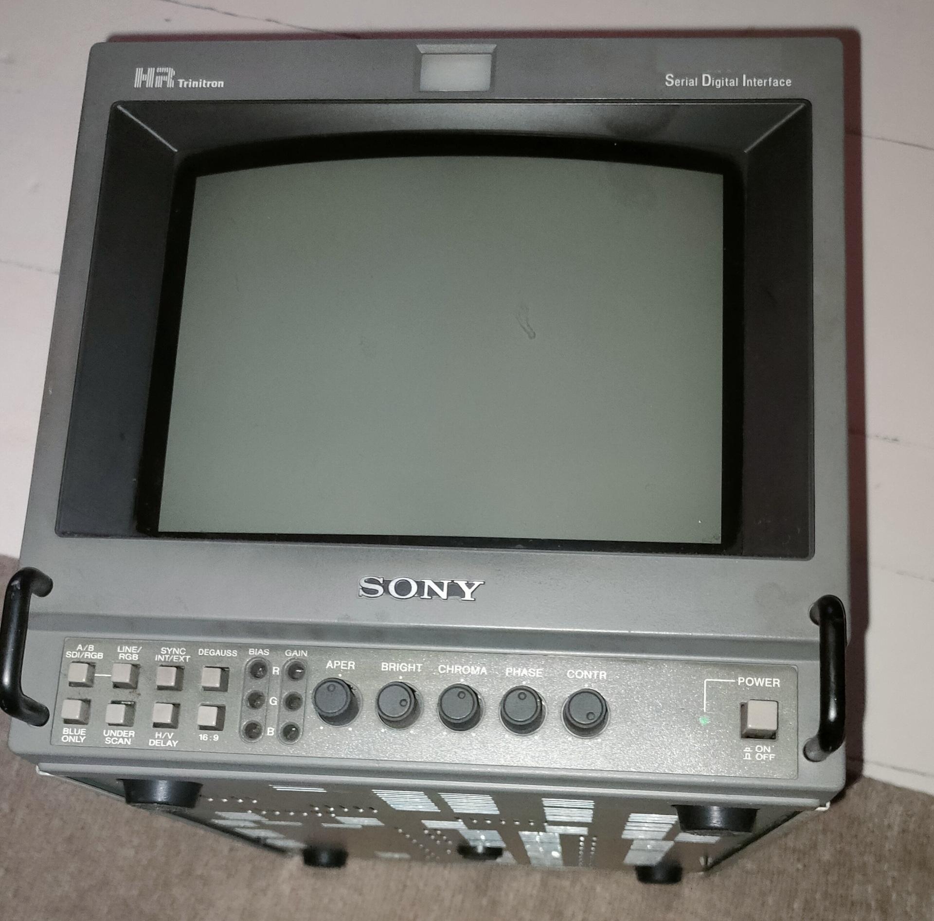
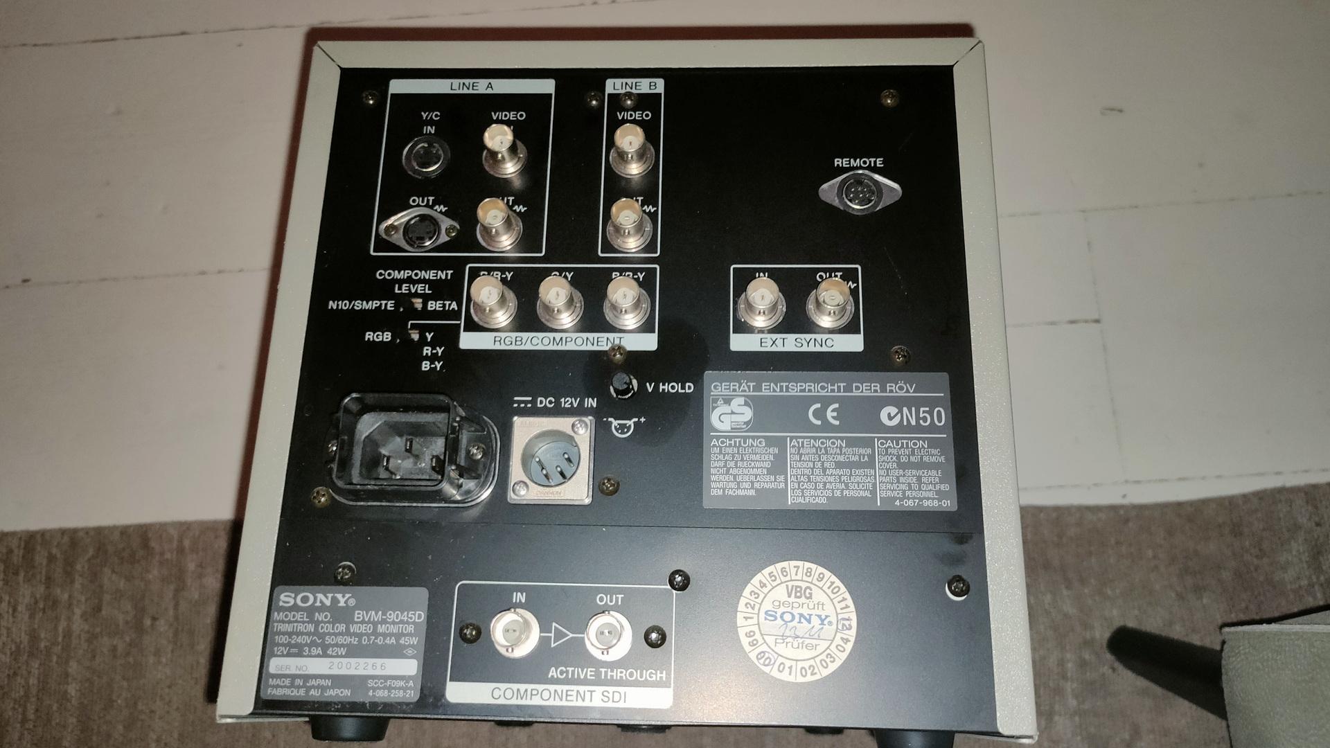
Got a Trinitron display from him, I was looking for this for a long time.
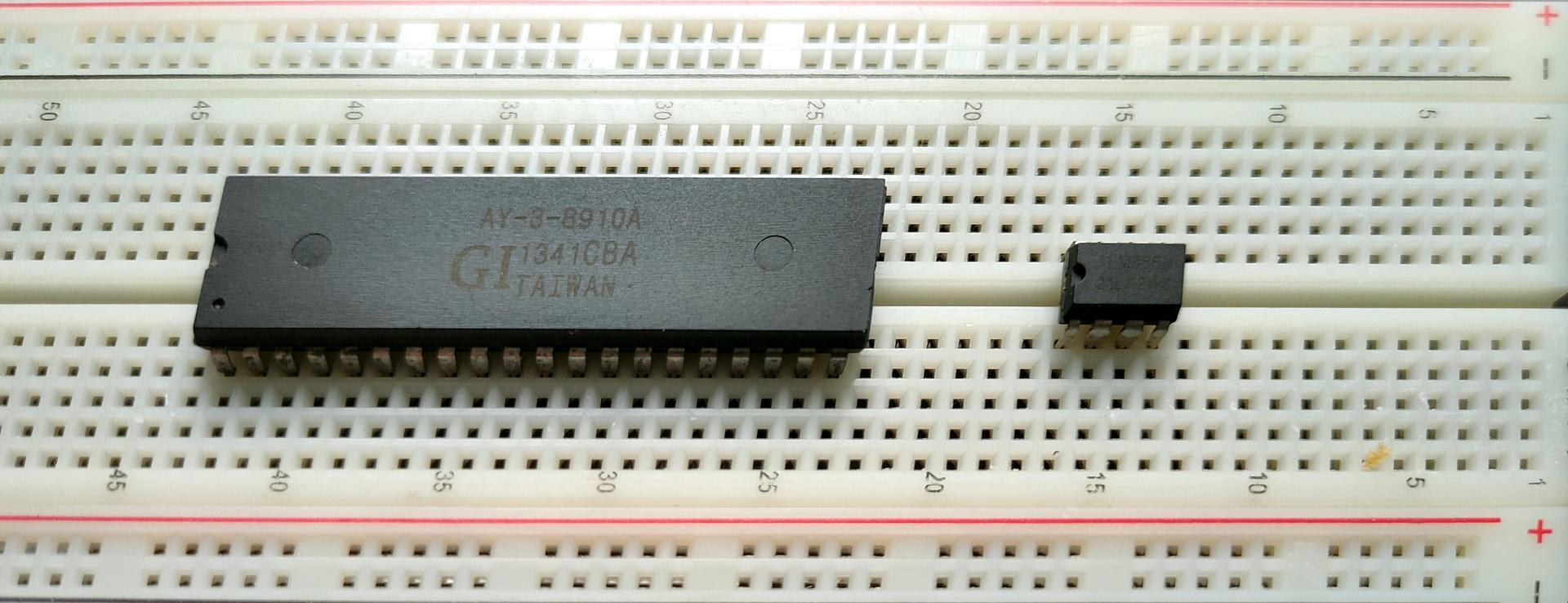
I’ve written about General Instrument AY-3-8910 before, here is some work I did today.
This sound chip i wanted to implement in my amiga, and now it’s a alternative for my 6502 computer. ( As an alternative setup for the SID chip. ) Btw this is the same kind of chip used in the Atari ST.
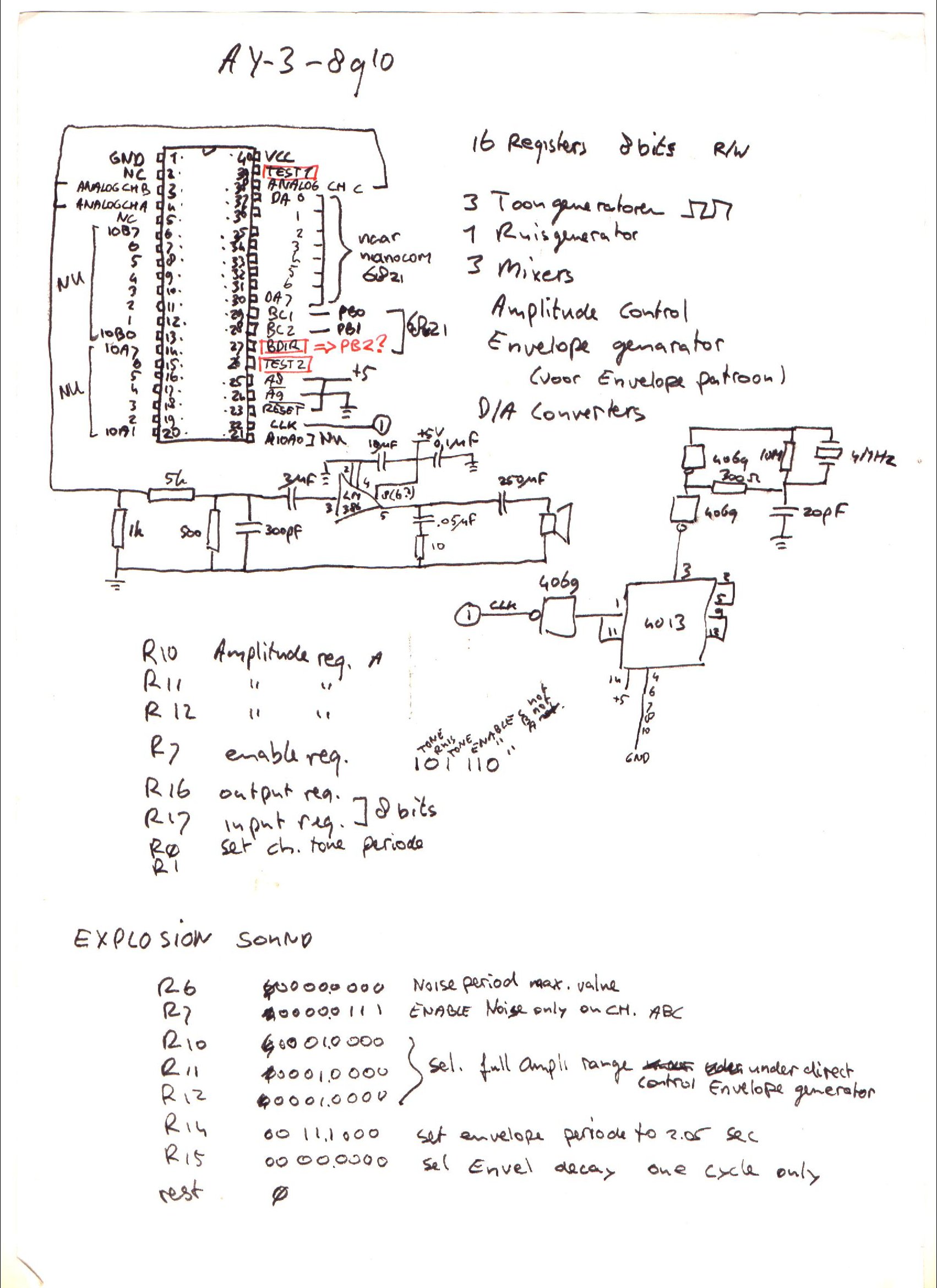
Above a Kicad drawing I made today, a little different from my design from the 90’s.
Below a movie clip I recorded today. Running a test setup using an Arduino nano and a sdcard reader. The sound is bad, this is due to clipping and the absence of multiple resistors and capacitors. Music is a register dump from a YM music file. Amplifier is a bare LM386.
UPDATE: 20240225
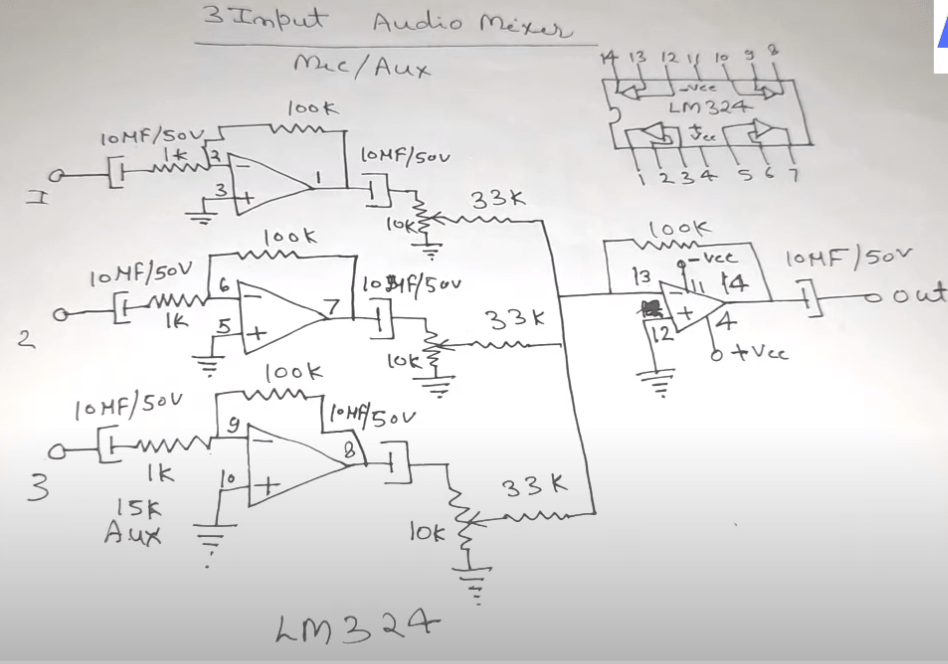
I don’t like tying those three outputs together, and amplifying those.
So I’m going to use a LM324 i’ve got left from my 8085 interface, and make a 3-channel amplifier.
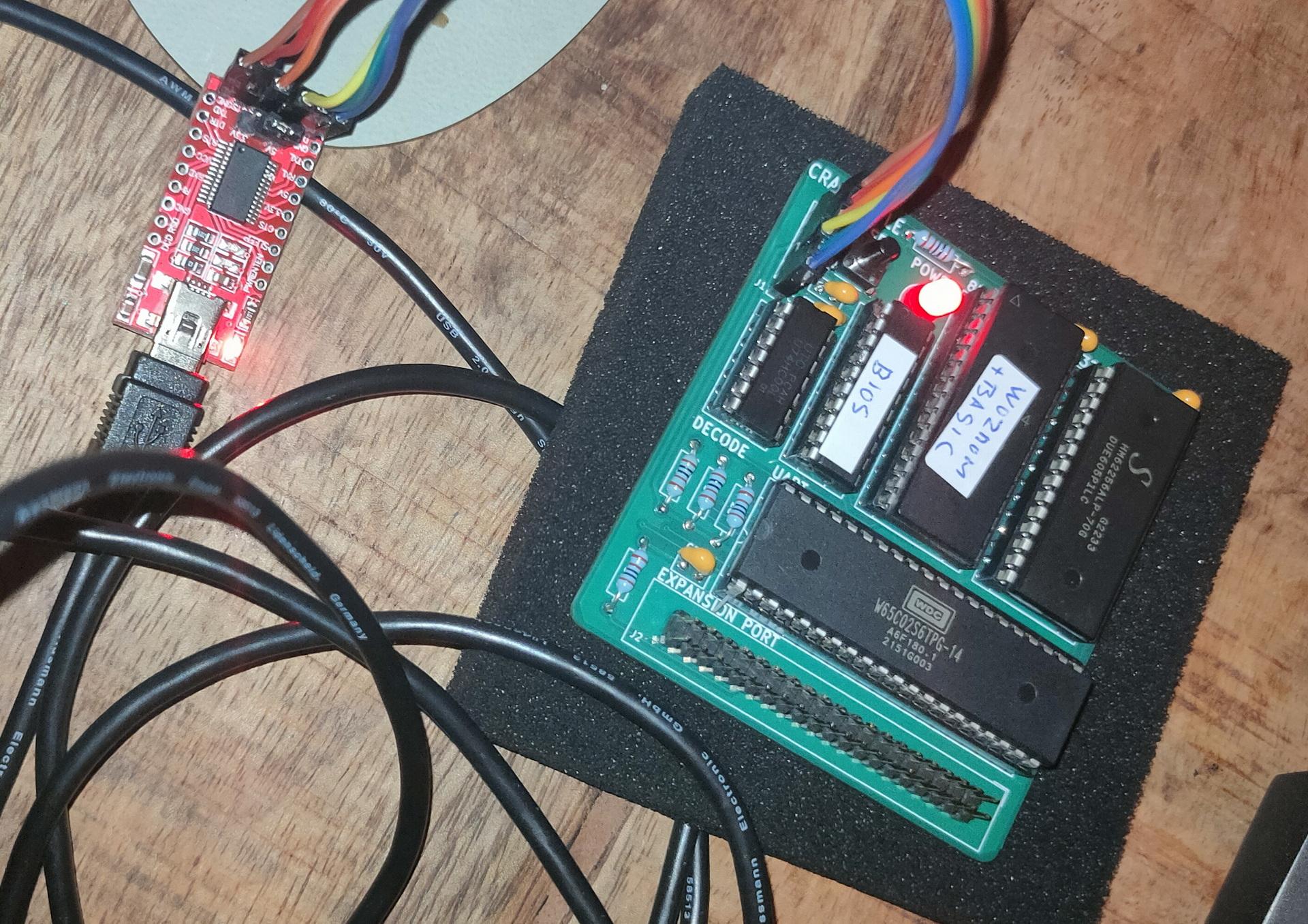
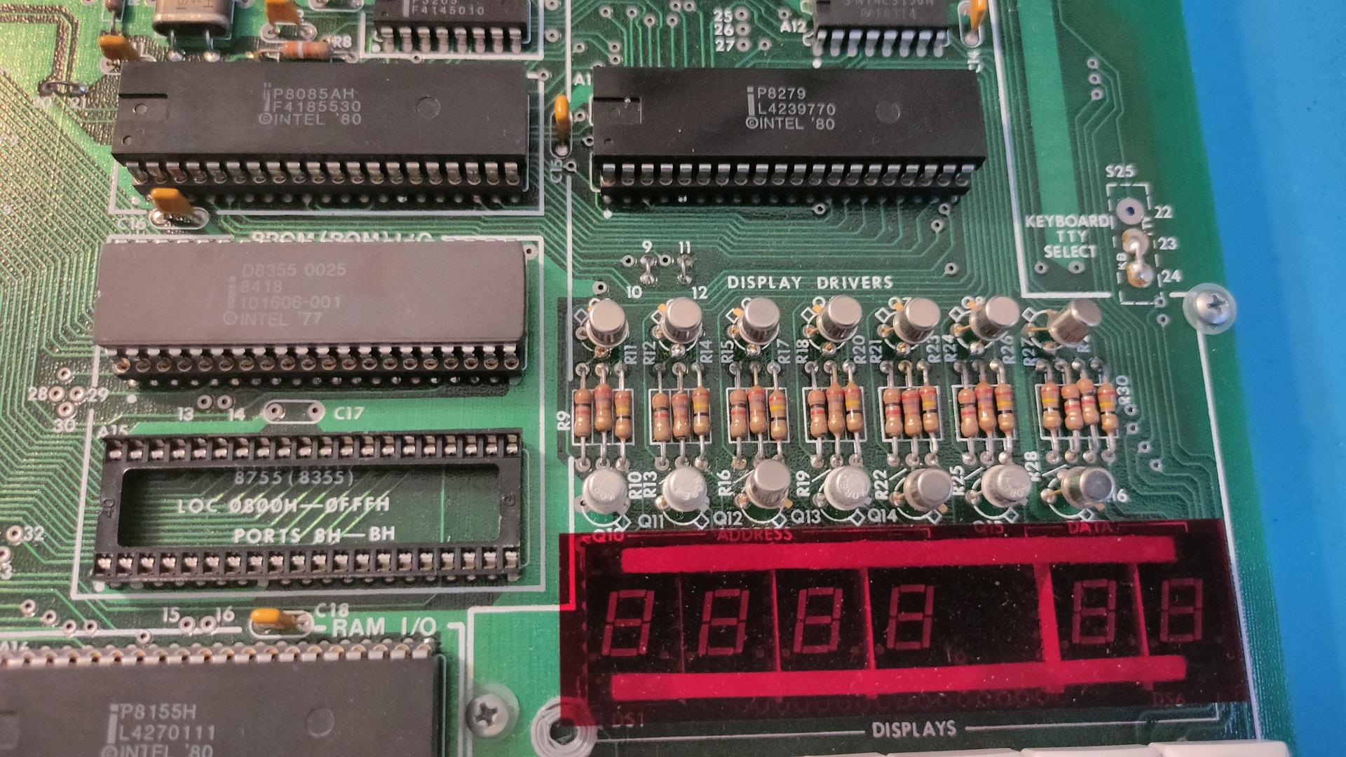
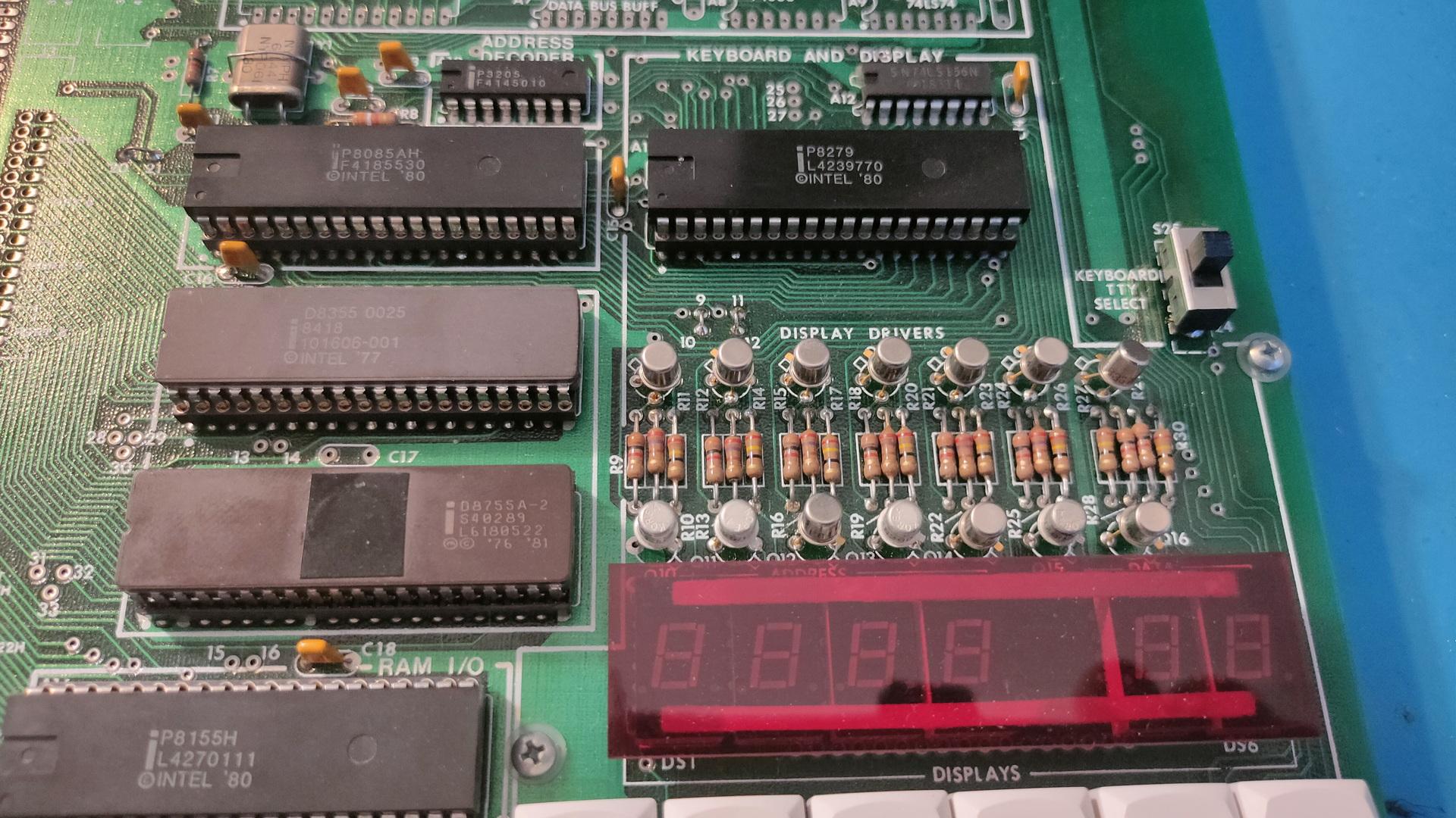
It has an EPROM with Wozmon and Basic for now. I have to redo the address decoder, but I like the simple serial interface by Geoffrey. (I hate the PIC18F15Q41, made by Microchip, but still the best minimal option .. for now)
Probably the last time i’ve used a pic was in 1998
I’ve posted in the past something about pl/m. Today i got this running again in a dosbox.
The PL/M programming language (an acronym of Programming Language for Microcomputers) is a high-level language conceived and developed by Gary Kildall in 1973 for Intel’s microprocessors.
PLM86 PROGRAM.PLM
LINK86 PROGRAM.OBJ, PLM\DOSLIBS.LIB, PLM\UTILS.LIB TO %1.LNK INITCODE
LINK PROGRAM.LNK;;;
Tic Tac Toe in PLM
bke:do;
/*DOEL:                                              */
/*Dit programma is boter kaas en eieren voor twee    */
/*spelers, er wordt gecontroleerd of iemand gewonnen */
/*heeft. (Je speelt niet tegen de computer)          */
/*UPDATE:12/2/90,15/2/90,18/2/90  RELDATE:19/2/90    */
/*PROGRAMMER:H.M.Aanstoot                            */
/*UPDATE 5/3/90 1:13:23                              */
/*De volgende 4 regels zorgen ervoor dat de compiler */
/*de PLM  DOS,UTIL routines die op disk staan        */
/*meestuurt naar de linker                           */
/* bla bla 2de versie met STRINGS!! eindelijk gelukt */

$include(plm\doslibs.inc)
$include(plm\doslibs.dcl)
$include(plm\utils.dcl)
dcl naam(3)           pointer;
dcl plaats(9)         word;
dcl teken(2)          pointer;
dcl aanzet            word;
dcl loop              word;
dcl a                 word;
dcl winnaar           word;
dcl nummer            word;
dcl item              word;
dcl error_status      word;

spelerzet:procedure;
call dsso(naam(aanzet));
call dsso(@(', geef een getal: $'));
invoer:
nummer=dsin;
nummer=nummer-48;
if nummer<1 or nummer>9 then goto invoer;
if plaats(nummer)<>0 then goto invoer;
call dso(nummer+48);
plaats(nummer)=aanzet;
end spelerzet;

update:procedure;
item=1;
call dsso(@(cr,lf,'+-----+-----+-----+',cr,lf,eos));
call dsso(@('|     |     |     |',cr,lf,eos));
call dso(124);call zet;call dso(124);call zet;call dso(124);call zet;
 call dsso(@(124,cr,lf,eos));
call dsso(@('|     |     |     |',cr,lf,eos));
call dsso(@('+-----+-----+-----+',cr,lf,eos));
call dsso(@('|     |     |     |',cr,lf,eos));
call dso(124);call zet;call dso(124);call zet;call dso(124);call zet;
 call dsso(@(124,cr,lf,eos));
call dsso(@('|     |     |     |',cr,lf,eos));
call dsso(@('+-----+-----+-----+',cr,lf,eos));
call dsso(@('|     |     |     |',cr,lf,eos));
call dso(124);call zet;call dso(124);call zet;call dso(124);call zet;
 call dsso(@(124,cr,lf,eos));
call dsso(@('|     |     |     |',cr,lf,eos));
call dsso(@('+-----+-----+-----+',cr,lf,eos));

  call dsso(@('    1   2   3',cr,lf,eos));
  call dsso(@('    4   5   6',cr,lf,eos));
  call dsso(@('    7   8   9',cr,lf,eos));
end update;


zet:procedure;
if plaats(item)=0 then call dsso(@('     $'));
if plaats(item)=1 then call dsso(@('  X  $'));
if plaats(item)=2 then call dsso(@('  O  $'));
item=item+1;
end zet;

check:procedure;
   do a=1 to 2;
   if plaats(1)=a and plaats(2)=a and plaats(3)=a then winnaar=a;
   if plaats(4)=a and plaats(5)=a and plaats(6)=a then winnaar=a;
   if plaats(7)=a and plaats(8)=a and plaats(9)=a then winnaar=a;

   if plaats(1)=a and plaats(4)=a and plaats(7)=a then winnaar=a;
   if plaats(2)=a and plaats(5)=a and plaats(8)=a then winnaar=a;
   if plaats(3)=a and plaats(6)=a and plaats(9)=a then winnaar=a;

   if plaats(1)=a and plaats(5)=a and plaats(9)=a then winnaar=a;
   if plaats(3)=a and plaats(5)=a and plaats(7)=a then winnaar=a;
   end;
end check;


hoofdprogramma:
winnaar=3;
naam(1)=@('Speler 1$');
naam(2)=@('Speler 2$');
naam(3)=@('Niemand$');
do a=1 to 9; plaats(a)=0; end;
teken(1)=@('kruisje$');
teken(2)=@('rondje$');
aanzet=1;

    do loop=1 to 9;
    call update;
    call check;
    if winnaar<>3 then goto gewonnen;
    call spelerzet;
    aanzet=3-aanzet;
    end;

call update;
gewonnen:
call dsso(naam(winnaar));
call dsso(@(' heeft gewonnen',cr,lf,eos));
if winnaar=3 then call dsso(@('Helaas, pindakaas!$'));
			 else call dsso(@('Gefeliciteerd ermee!$'));

call dexit(error_status);
end;
A dentro (Combination of demo and intro.) from 1995
It using only background colors behind existing text to display the dentro text. There is (somewhere) a version with animations.
New work:
Booting from floppy, showing a flash screen in mode 13h. Starting a trackloader, which loads a raw adlib file and plays it. All sectors written to floppy using my new sector writer. WOOT .. music at boot time!
Sector writer
use16
org 0100h
; 0 0 1
; bootblock with flashcode
	mov cl,1  ; start
	mov al,1  ; # sectors
	mov dh,0  ; head
	mov bx,bootblock
	call wrtsector

; flash image
	mov cl,8
	mov al,4
	mov dh,0
	mov bx,gfx
	call wrtsector

; Music loader
	mov cl,7  ; start
	mov al,1  ; # sectors
	mov dh,0  ; head
	mov bx,nextpart
	call wrtsector

; Music raw
	mov cl,13  ; start
	mov al,4  ; # sectors
	mov dh,0  ; head
	mov bx,musicraw
	call wrtsector

	jmp do_exit

printerror:
	push cs		; make ds same as cs
	pop ds
	MOV DX,TxtErr1	; error
	MOV AH,09h
	INT 21h
	mov ax,4c00h
	int 21h
do_exit:
	mov ax,4c00h
	int 21h
wrtsector:
;       On entry:      AH         03h
;                      AL         Number of sectors to write
;                      CH         Cylinder number (10-bit value; upper 2 bits
;                                 in CL)
;                      CL         Starting sector number
;                      DH         Head number
;                      DL         Drive number
;                      ES:BX      Address of memory buffer
;
;       Returns:       AH         Status of operation (See Service 01h)
;                      AL         Number of sectors written
;                      CF         Set if error, else cleared

	cld
	mov ah, 3h    ; int13h function 2
	mov ch, 0     ; from cylinder number 0
	mov dl,0
	push cs
	pop es
	int 13h
	jc printerror
ret

TxtErr1:	 DB "Error!",7,10,13,"$"

bootblock:
	file 'flash_b.bin'
gfx:
	file 'flashgfx.raw'
nextpart:
	file 'nextpart.bin'
musicraw:
	file 'LVLINTRO.RAW'
I wanted to know how a floppy differs from a floppy. So i wrote below code to fill each sector on a floppy disk or image with information at the start of each sector. (Head, Cylinder and Sector)
empty.bin was made using dd if=/dev/zero of=empty.bin count=1 bs=512
use16
org 0100h

	mov ch,0  ; cyl
	mov cl,1  ; sector
	mov dh,0  ; head
nextsector:
	mov bx,empty
	mov [empty],dh
	mov [empty+1],ch
	mov [empty+2],cl
	push cx
	push ax
	push dx
	call printer
	call wrtsector
	pop dx
	pop ax
	pop ax
	inc cl
	cmp cl,19
	jnz nextsector
	mov cl,1
	inc ch
	cmp ch,79
	jnz nextsector
; other side
	mov dh,1
	mov ch,0
	mov cl,1

nextsector1:
	mov bx,empty
	mov [empty],dh
	mov [empty+1],ch
	mov [empty+2],cl
	push cx
	push ax
	push dx
	call wrtsector
	pop dx
	pop ax
	pop ax
	inc cl
	cmp cl,19
	jnz nextsector1
	mov cl,1
	inc ch
	cmp ch,79
	jnz nextsector1


	jmp do_exit

printerror:
	push cs		; make ds same as cs
	pop ds
	MOV AX,3	; default text mode 3
	INT 10h
	MOV DX,TxtErr1	; error
	MOV AH,09h
	INT 21h
	mov ax,4c00h
	int 21h


do_exit:
	mov ax,3
	int 10h
	mov ax,4c00h
	int 21h

printer:
	push cx
	push dx
	mov dl,dh
	mov ah, 02h
	add dl, 30h
	int 21h
	mov dl,ch
	add dl, 30h
	int 21h
	mov dl,cl
	add dl, 30h
	int 21h
	mov dx,13
  mov ah,2
  int 21h
  mov dx,10
  mov ah,2
  int 21h
	pop dx
	pop cx
	ret

wrtsector:
;       On entry:      AH         03h
;                      AL         Number of sectors to write
;                      CH         Cylinder number (10-bit value; upper 2 bits
;                                 in CL)
;                      CL         Starting sector number
;                      DH         Head number
;                      DL         Drive number
;                      ES:BX      Address of memory buffer
;
;       Returns:       AH         Status of operation (See Service 01h)
;                      AL         Number of sectors written
;                      CF         Set if error, else cleared
;

	cld
	mov ah, 3h    ; int13h function 2
	mov al,1
	mov dl,0
	push cs
	pop es
	int 13h
	jc printerror
ret

TxtErr1:	 DB "Error!",7,10,13,"$"

empty:
	file 'empty.bin'
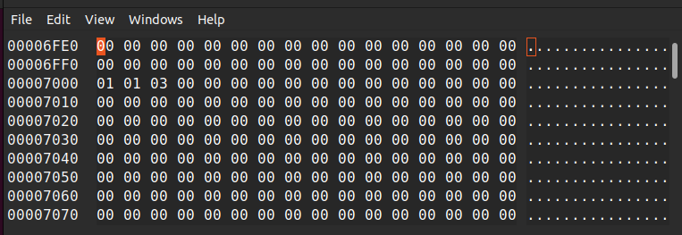
Viewing the floppy image with ghex
Offset 7000 = Head 1, Cylinder 1 and sector 3
When doing times 512 – ($-$$) db 0 to fill binaries to 512 bytes, you could cat the sectors to a disk/file with this knowledge.
Working on a library of functions (sector loaders, color palette, vert/hor retrace functions)
Laying out a memory map for the demo
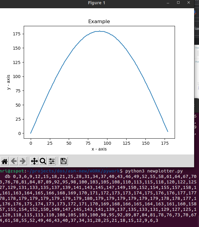
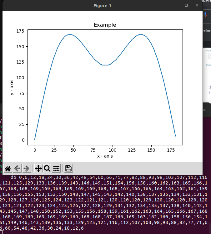
Below the output of the sin/cos generator ( see used in video below ) (It also shows a visual plot of the function)
Two examples included in the python script to generate DB enties, which can be assembled in your source code (just include or copy paste)
Source code python script
# importing the required module
import matplotlib.pyplot as plt
import numpy as np
import math

# Change these
numberofdatapoints = 360
maxamp = 180
howmuchfromwave = 0.5
numberofharmonies = 1
# Number of harmonies are sin/cos additions in the calculation line below

# not here
step = 360/numberofdatapoints*howmuchfromwave
offset = maxamp
maxamp = maxamp / numberofharmonies
offset = 0


x = [ ]

for xv in range(numberofdatapoints):
    xvstep=xv * step
# Calculation line
#    datapoint=np.sin(math.radians(xvstep))
# Double harmony example
    datapoint=np.sin(math.radians(xvstep)) + (np.sin(math.radians(xvstep*3))/2)

    datapoint=datapoint * maxamp
    datapoint=datapoint + offset
    x.append(int(datapoint))

print("    db ", end="")
print(*x, sep = ",")

# plotting the points
plt.plot(x)

# naming the x axis
plt.xlabel('x - axis')
# naming the y axis
plt.ylabel('y - axis')

# giving a title to my graph
plt.title('Example')

# function to show the plot
plt.show()
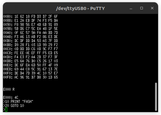
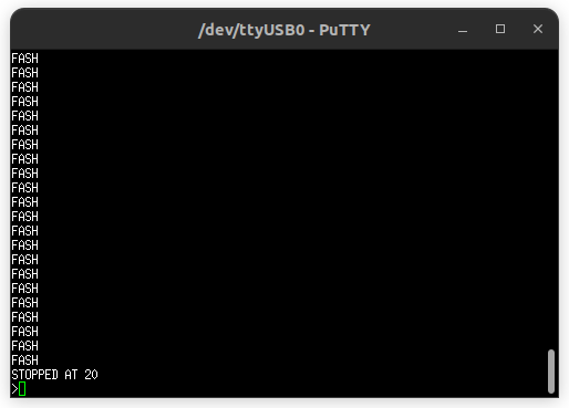
Minimalistic very fast boot loader flash screen effect
Graffiti bouncher test (probably ends up bounching a 320×400 image) This one uses the generated sintab (Using the python script above)
Test code for a text scroller
Code optimalisation/tricks
clear a (double) register? xor ax,ax is faster than mov ax,0h
Want to make ds pointer same as cs? Instead of mov ax,cs mov ds,ax use push cs pop ds
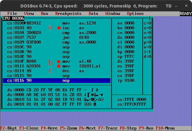
self modifying code mostly we just move data around, but you also can change the runtime code (instructions)
a – increment ax on line 103h
b – another part of the code/maybe in a interrupt 10Fh load al with 48h (thats the opcode for decrement (see c) 111h place the opcode in address 103h, which had 40h .. Now we changed the code to decrement next time
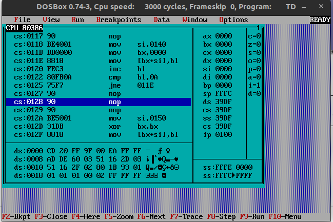
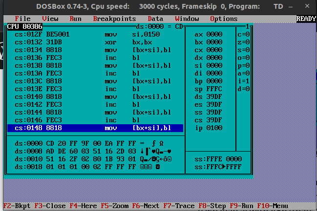
Speedcode/unrolled code
Populair on the C64 where resources are even more limited, you could use speedcode. Most of the speedcode you generate, due to its repeating lines. When looking at clock cycles you can save some extra cycles, by using a little more memory but saving on “expensive” loops.
Simple example
Left a funtion with a loop, right is the same but all instuctions sequencial
Left 15 bytes but 284 cycles
Right 39 bytes but only 102 cycles!
4
4
; below part 9 times
9
3
4
16 or 4
= 284 cycles

Speedcode
4
2 ; xor is faster
9
3 ; even 2 when you can use BX pair!
9
3
9
3
9
3
9
3
9
3
9
3
9
3
9
= 111 cycles (or 102 BX pair)
Moving memory blocks (No DMA)
;DS:(E)SI to address ES:(E)DI
    push cs          ; example to set es to code segment
    pop es
    mov si,1000      ; offset pointer source
    xor di,di        ; destination offset
    mov cx,320*100   ; number of transfers (See below words)
    mov ax,0a000h    ; Destination
    mov es,ax        ; destination segment
    cld              ; Clear direction flag set SI and DI to auto-increment
    rep movsw        ; repeat mov words! until number of transfers is 0
;
Short binary > bcd > dec (ascii) convert for numbers (0-99)
mov ax,01ch ; = 28
mov bx,0ah ; = 10
div bl ; divide BL by AX
       ; AX = 0802 ; Remainder/Divider
xchg ah,al ; change around (dont use if you want to keep little endian)
add ax,3030h ; offset to ascii 30=0 31=1
             ; ax ends up with 3238 .. 28
(NOTE, Dosbox can’t cope with the register speed, use real HW or PCem)
Effect using a edited photo I made from fireworks ..
Generating a RAW image and Palette, a in a new way
This bash script to convert BMP to Raw and a compiled colorpalette. (Note: this converts to 8 bit depth, the assembly code in the final assemby program converts to 6 for VGA mode 13h
So this time, i won´t have to use the standard VGA palette as mentioned in previous posts. (Gimp colors > indexed (255 colors) ; save as BMP, exclude colorspace information)
I’m using identify to extract the colorpalette, which i’m converting to DB entries for the fasm compiler