Quiet days, I working on some art.
But here are the last ‘prutsen’
My current Wifi setup
I’ve got a Wifi outside of my network for guest and emergency. ( 2 SSIDs)
Then a main Wifi router in my livingroom, one in my workshop/studio and one in the Attic (Electronics Lab)
So three main Wifi AccessPoints. These all have the same SSID’s but on different frequencies. That way i’ve got roaming in and outside my house.
Also some virtual accesspoints are configured.
I’ve got a main, folkband, IOT, guest-inside all on 2.4Ghz and 5Ghz.
I watched a lot of YT presentations about Mikrotik Wifi.
So I ended up with DFS safe channels 20Mhz for 2.4 and 20/40Mhz Ce for 5Ghz. (subchannels for each after some frequency scanning)
(2.4 does a failback to 20Mhz whenever there is even one client detected which connects only on this band. Such as some old IOT stuff)
2.4 in only 1,6 and 11 no overlap, each on another device.
300Mbps is sufficient for my wifi 🙂
I’ve got accesslists in place and i’m going to read into kicking a client when the signal strenght is below -50dB
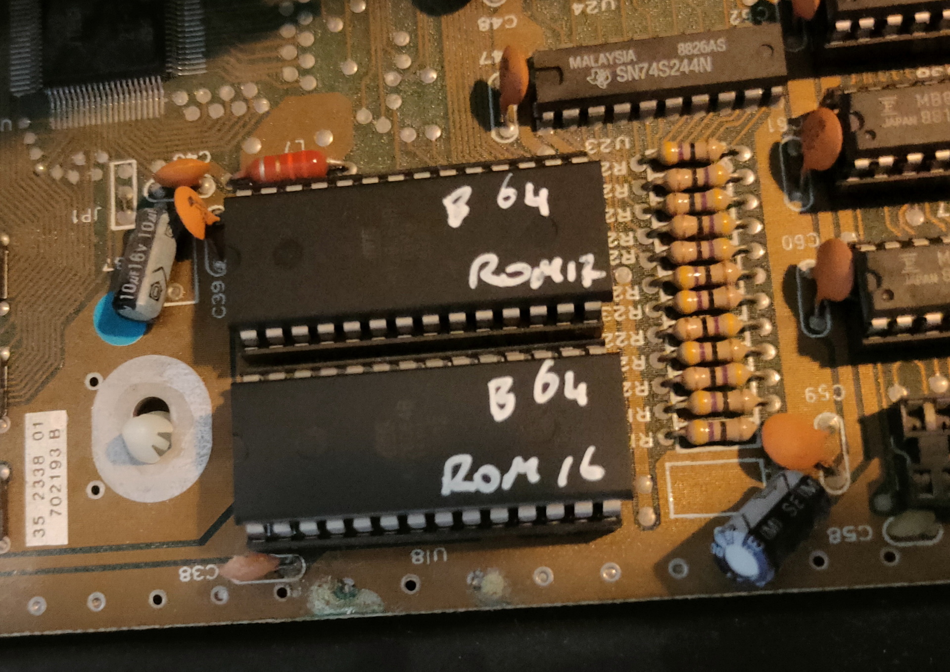
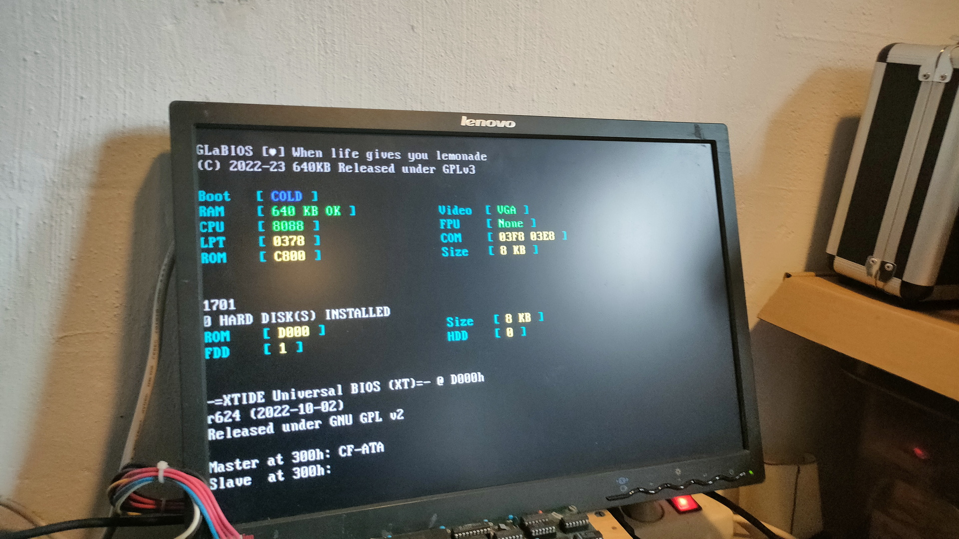
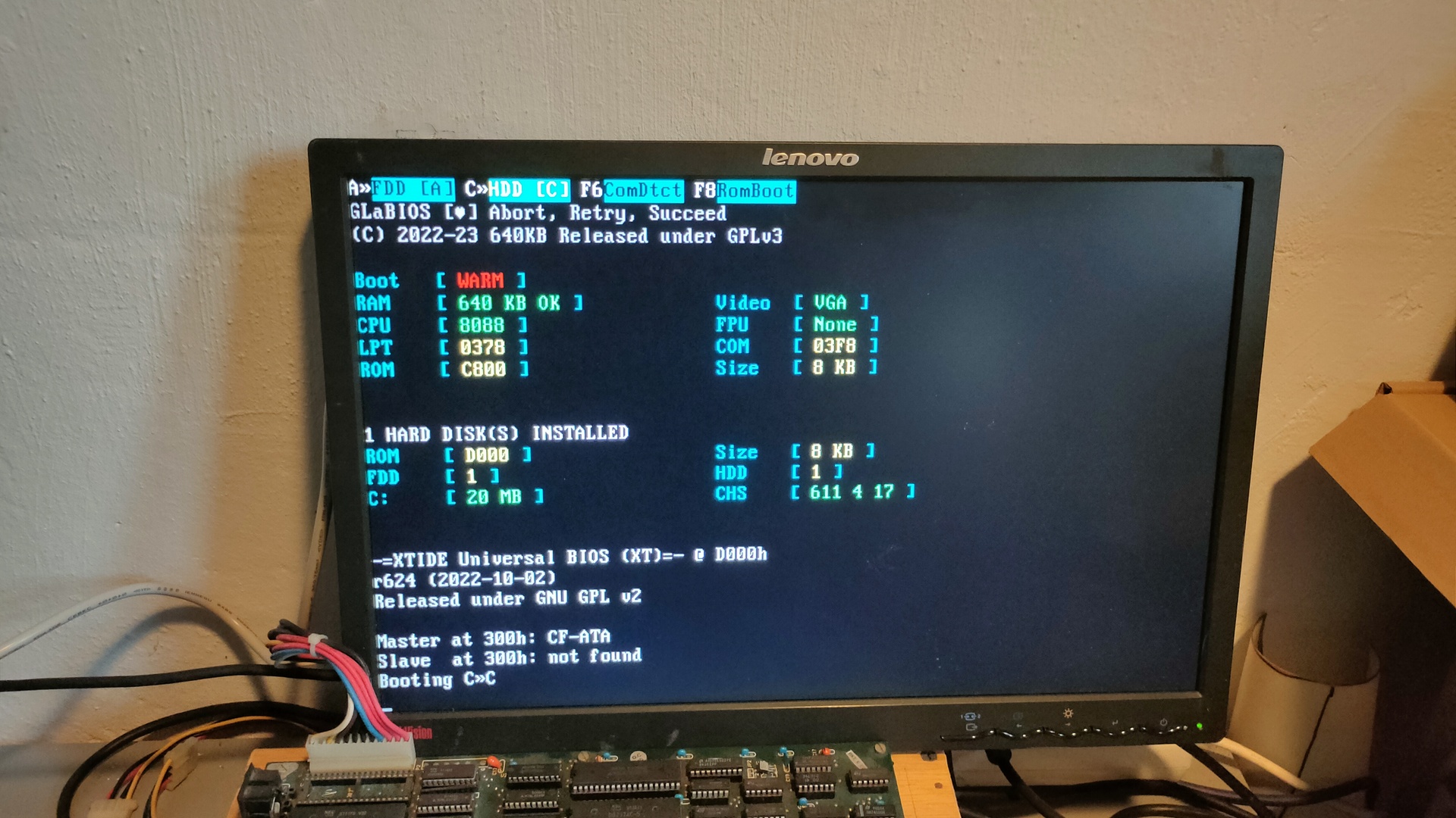
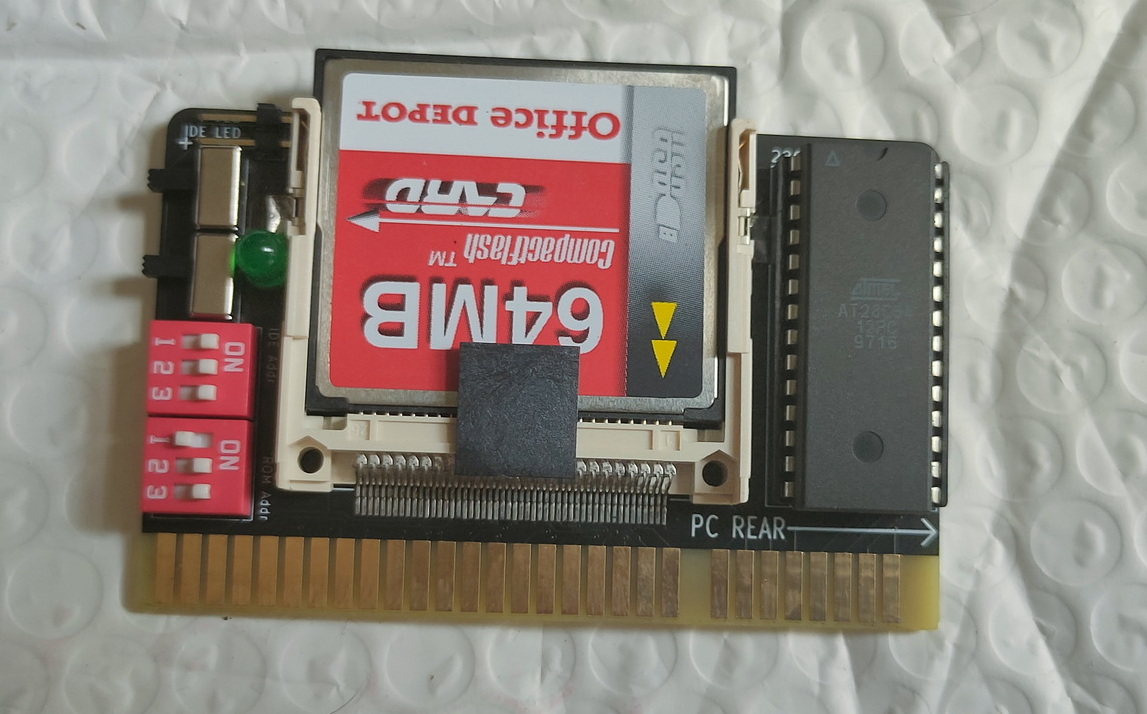
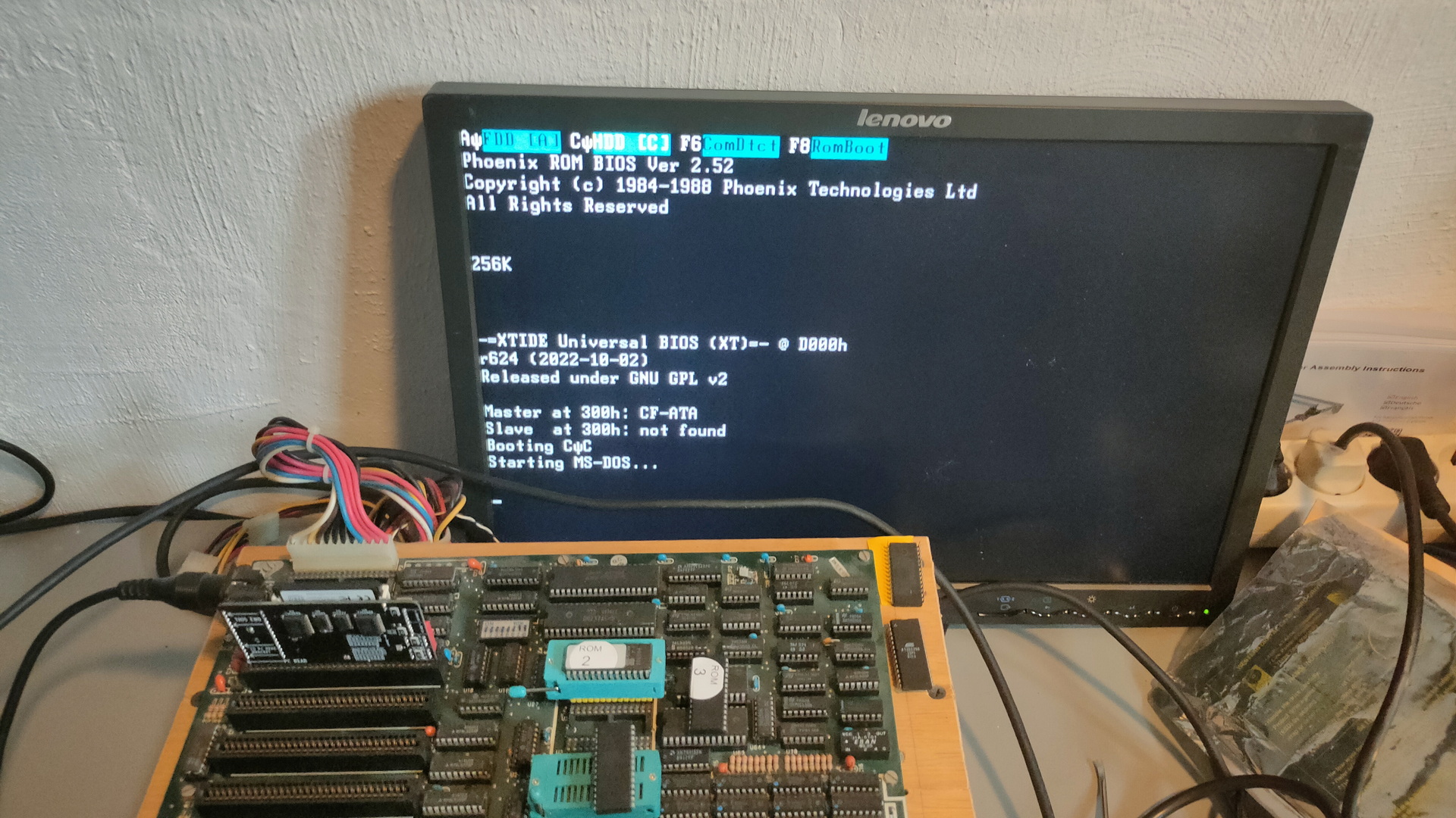
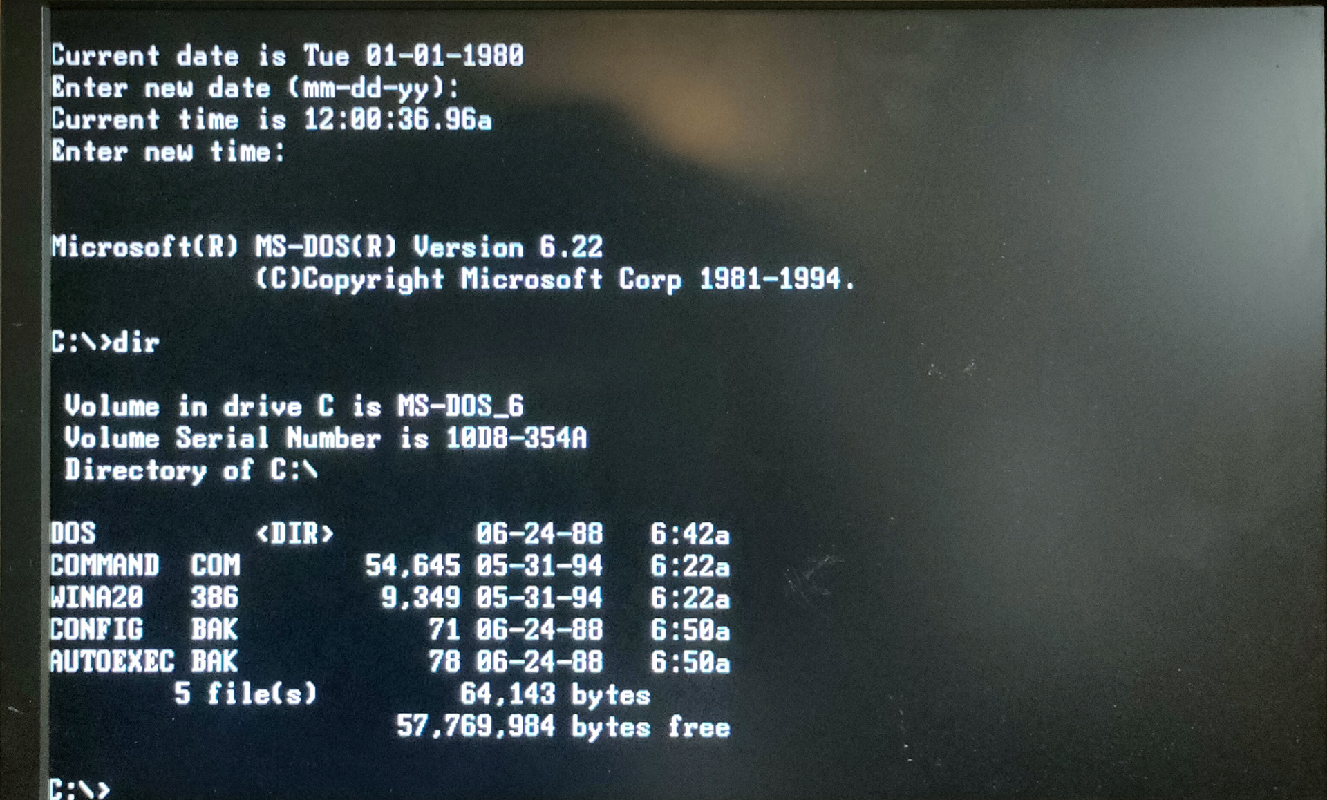
80386 (DX) Computer
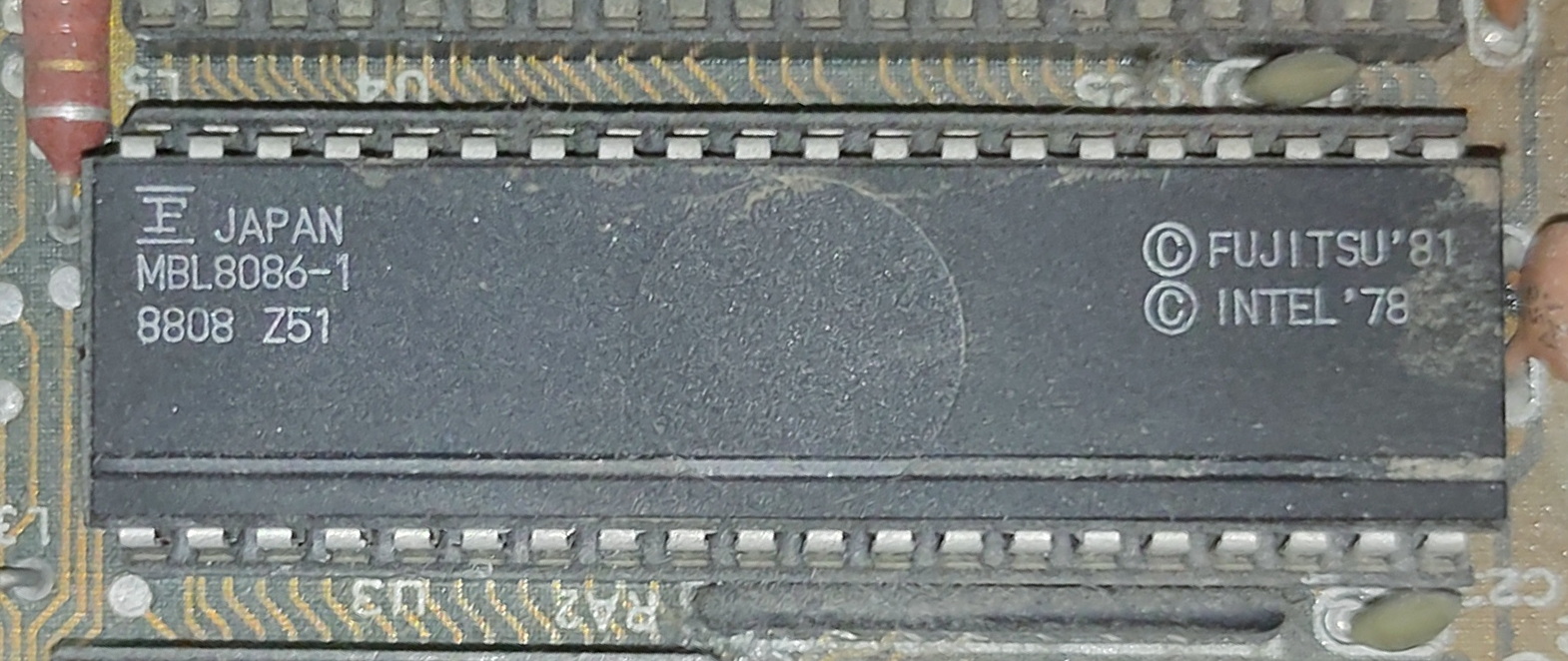
Besides my 8088 and 8086 machines I needed a machine which could run our old demo’s. So I bought a new toy.
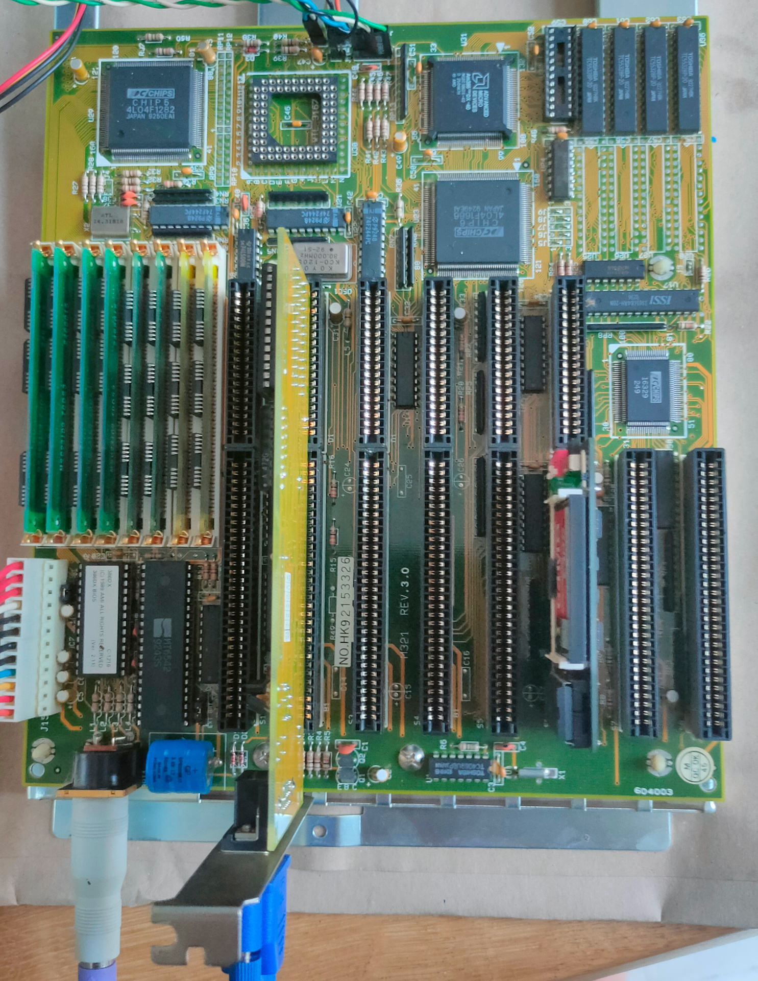
It has 8Mb Ram and runs at 40Mhz.
I’ve noticed that many of my VGA register manipulation code, can’t be run on a modern VGA monitor, I need to use a CRT for that .. Another thing to buy
Lilygo T-Display S3 Streaming
Not my code: https://github.com/Steve5451/esp32-stream-desktop
A very cool project!
Needed to fix arduino code, due to the TFT_eSPI library issues.
And I’ve got a S3 with another resolution, but that was an easy fix.
Then needed to reinstall nodejs with another version.
Had to modify the code because the tcp server would not start.
Weird errors logging, but in the end fixed … very cool
I probably end up designing a 3D printed case that looks like a monitor or tv.