As posted before, i found a cartridge in my collection a while ago. I don’t know where i’ve got this one from.
While searching on the internet for more information, i really couldn’t find anything about it. Not even on collectors sites.
Where did it come from, what does it do?
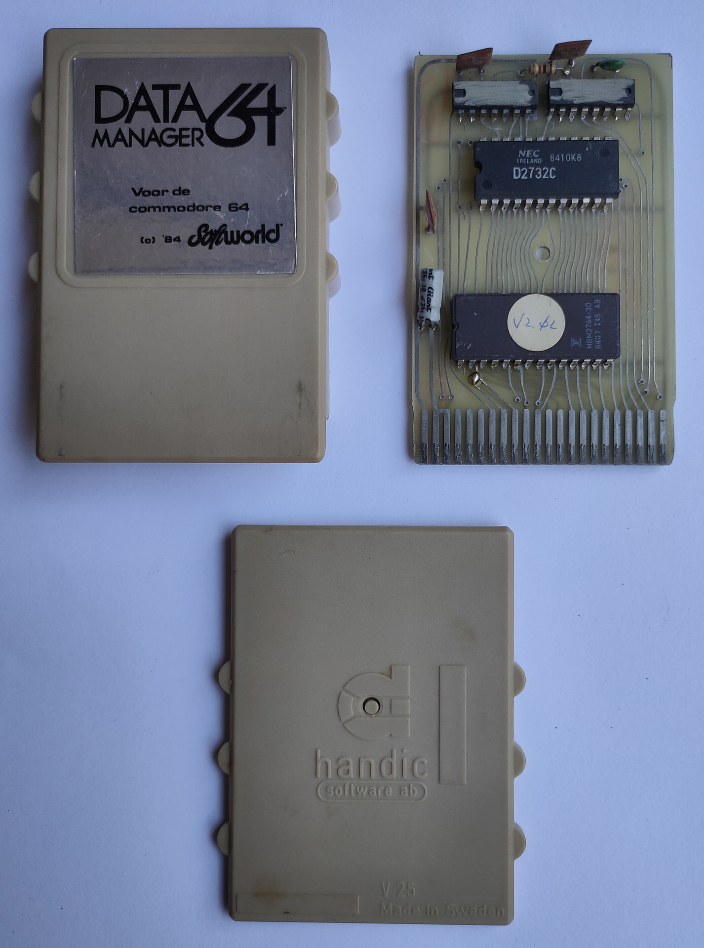
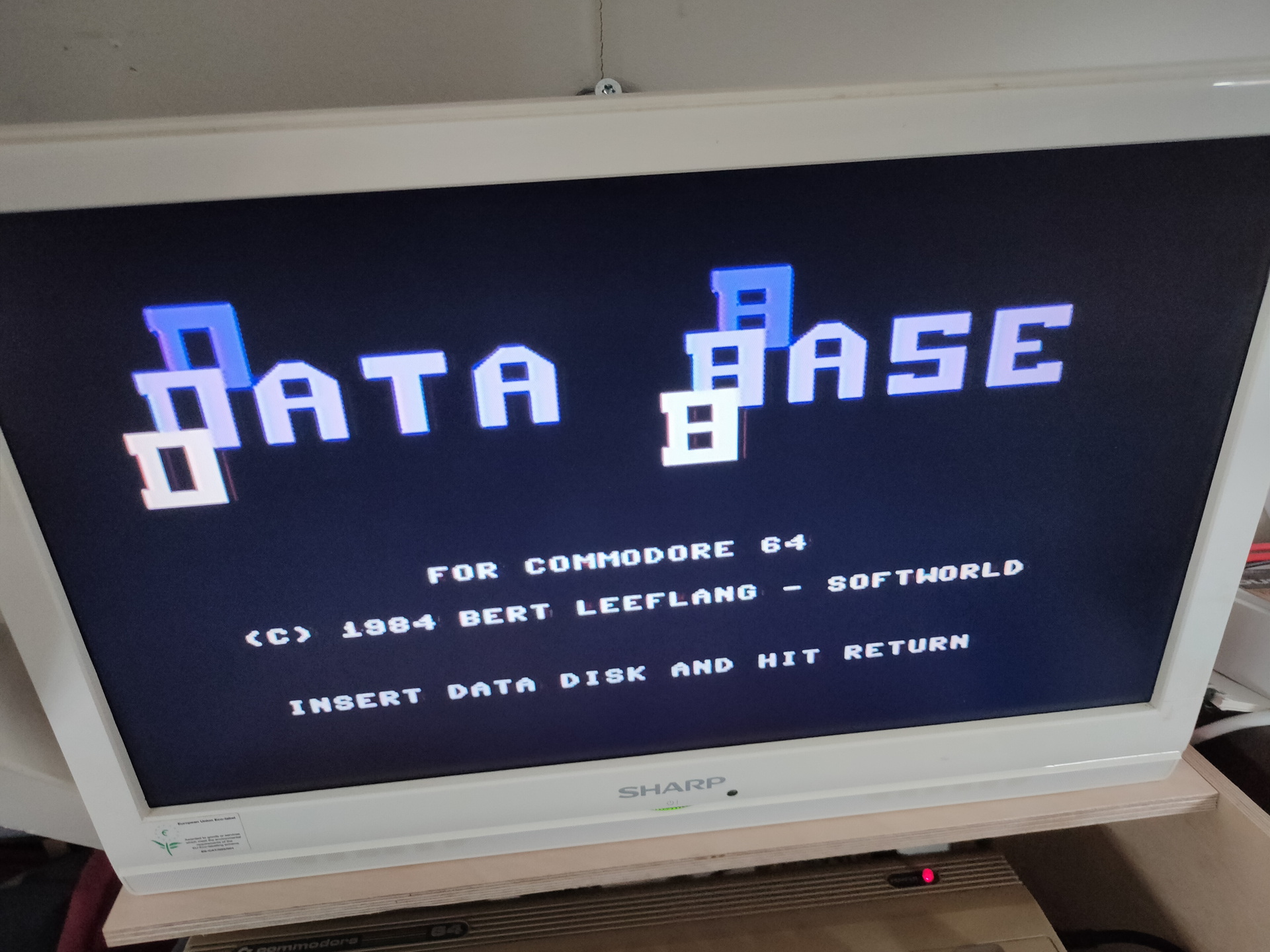
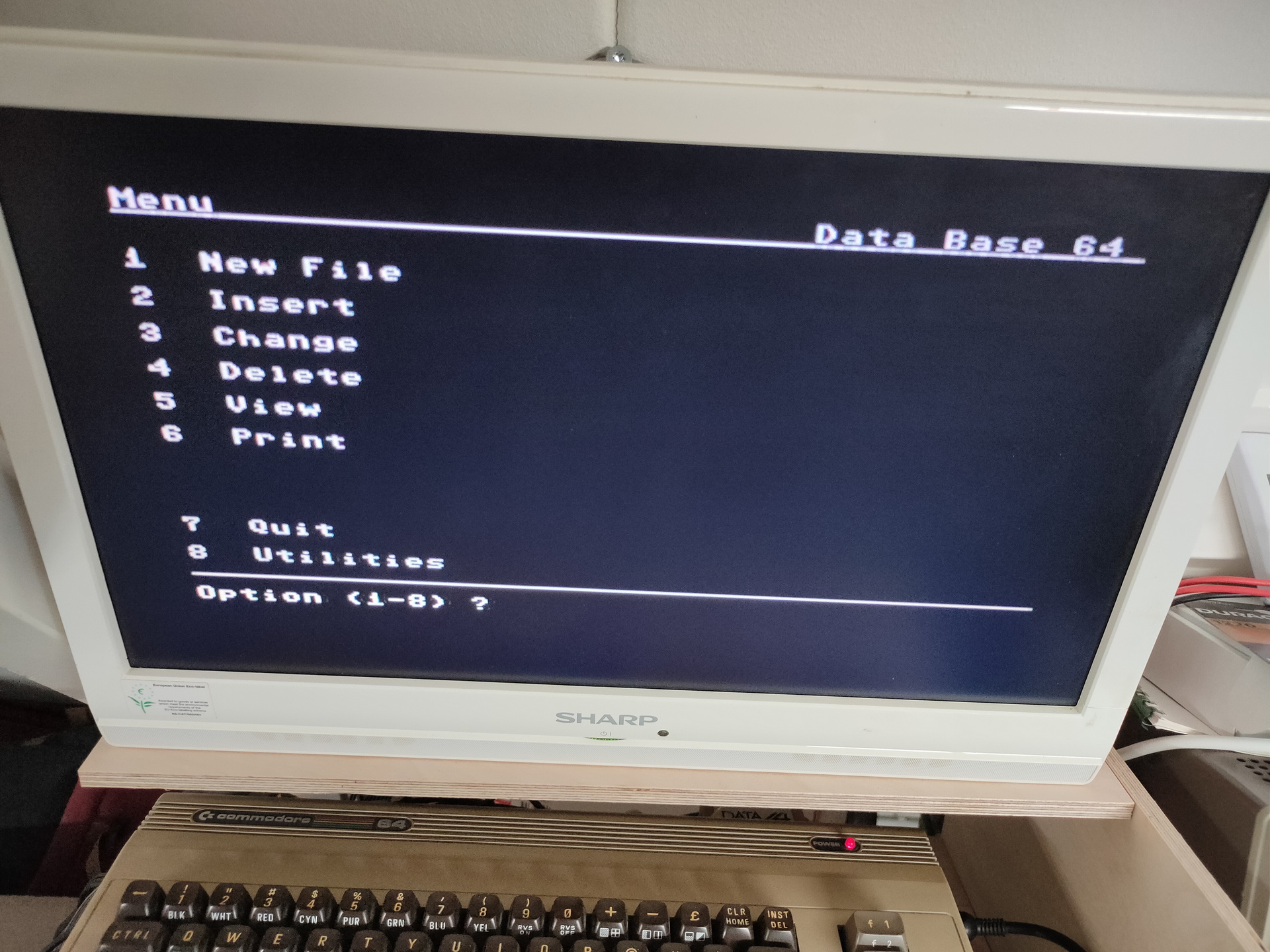
It says: Data Manager 64 (1984) , Softworld and Handic.
I can find many cartridges by Handic. I’ve checked all database/filers i could find. Non looked like this.
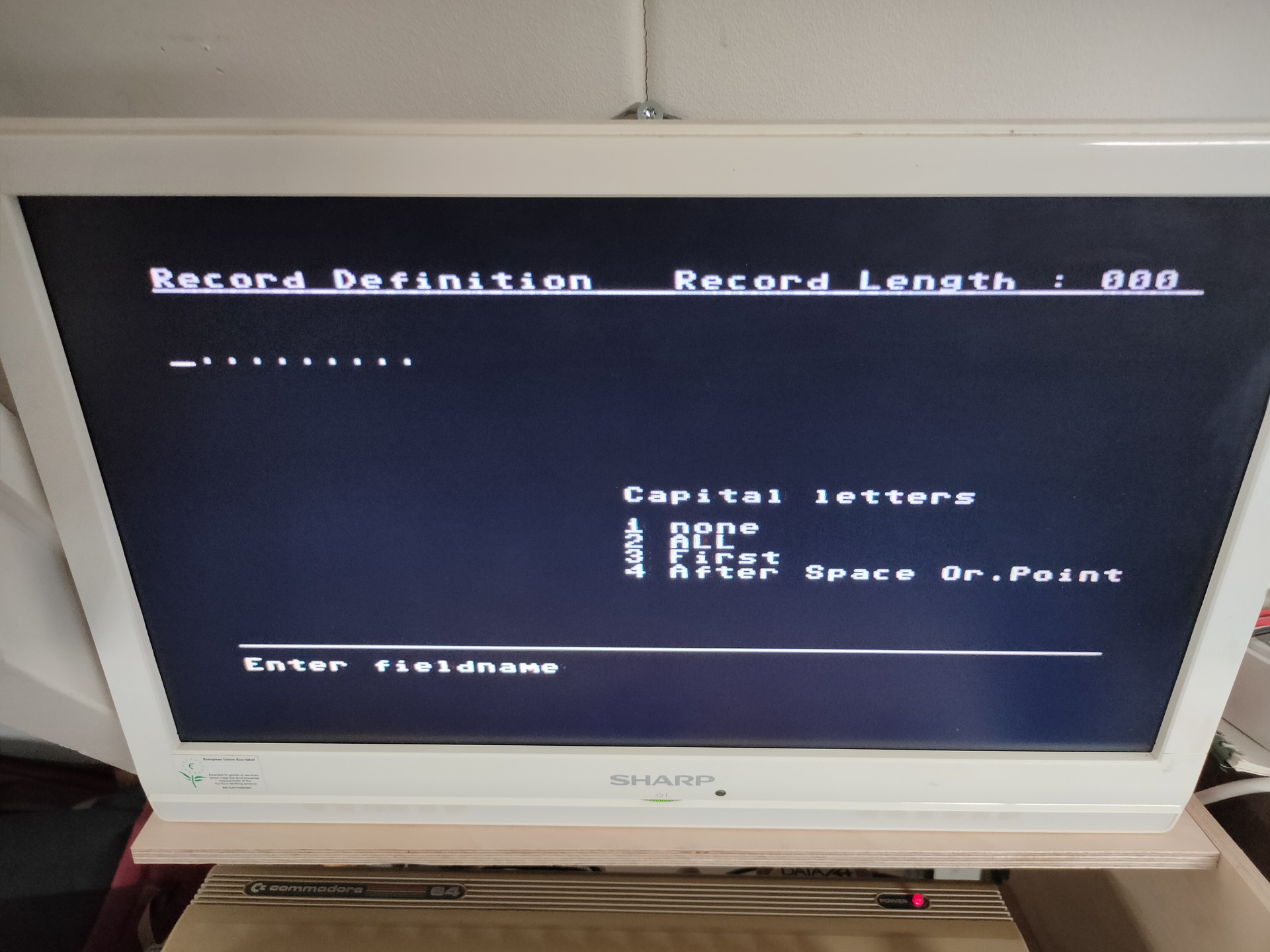
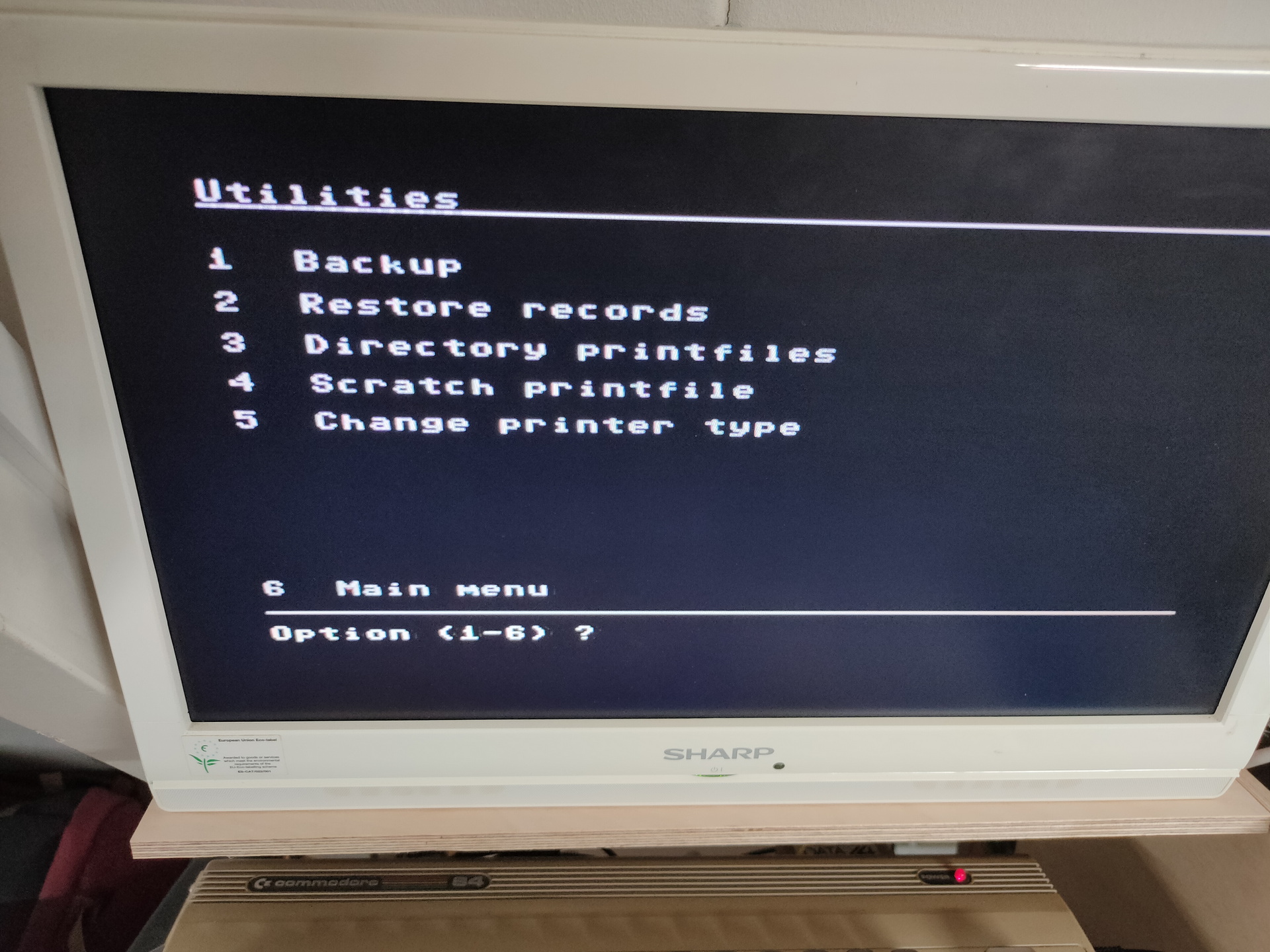
Some screenshots
Next to try .. Dumping the cartridge to file. Probably by changing the way the C64 starts a autostart cartridge. So i have to modify the cartridge port, and put a cross connection on the lines EXROM and GAME, this will change the memory addresses ($8000/$A000) where a cartridge is placed. Then the commodore will start normally, and i can dump the cartrige memory locations to a file.
So pins 8 and 9 have to be switched around. The C64 autostarts a cartridge when it find certain data on $8000
Meanwhile i try to contact some collectors of cartridges.
Next week i’ll be going to May Contain Hackers 2022, what to bring? My old friend Bigred will be there, many others couldn’t make it …
What to bring and do:
Laptops
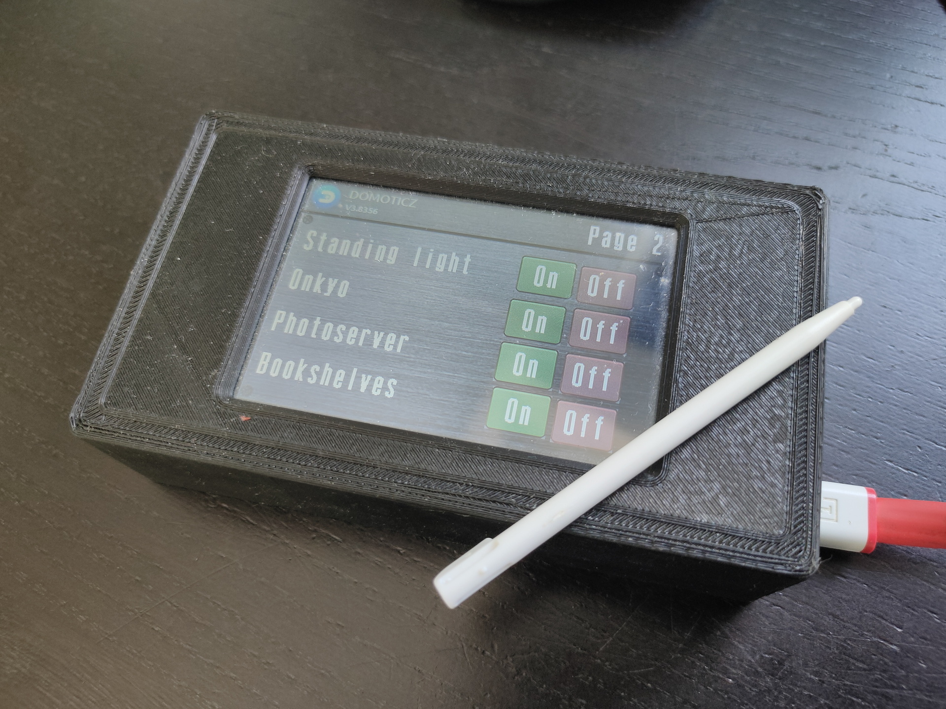
Arduino touch project?
My new 6502 breadboard computer?
The DVB-T / DAB / FM stick
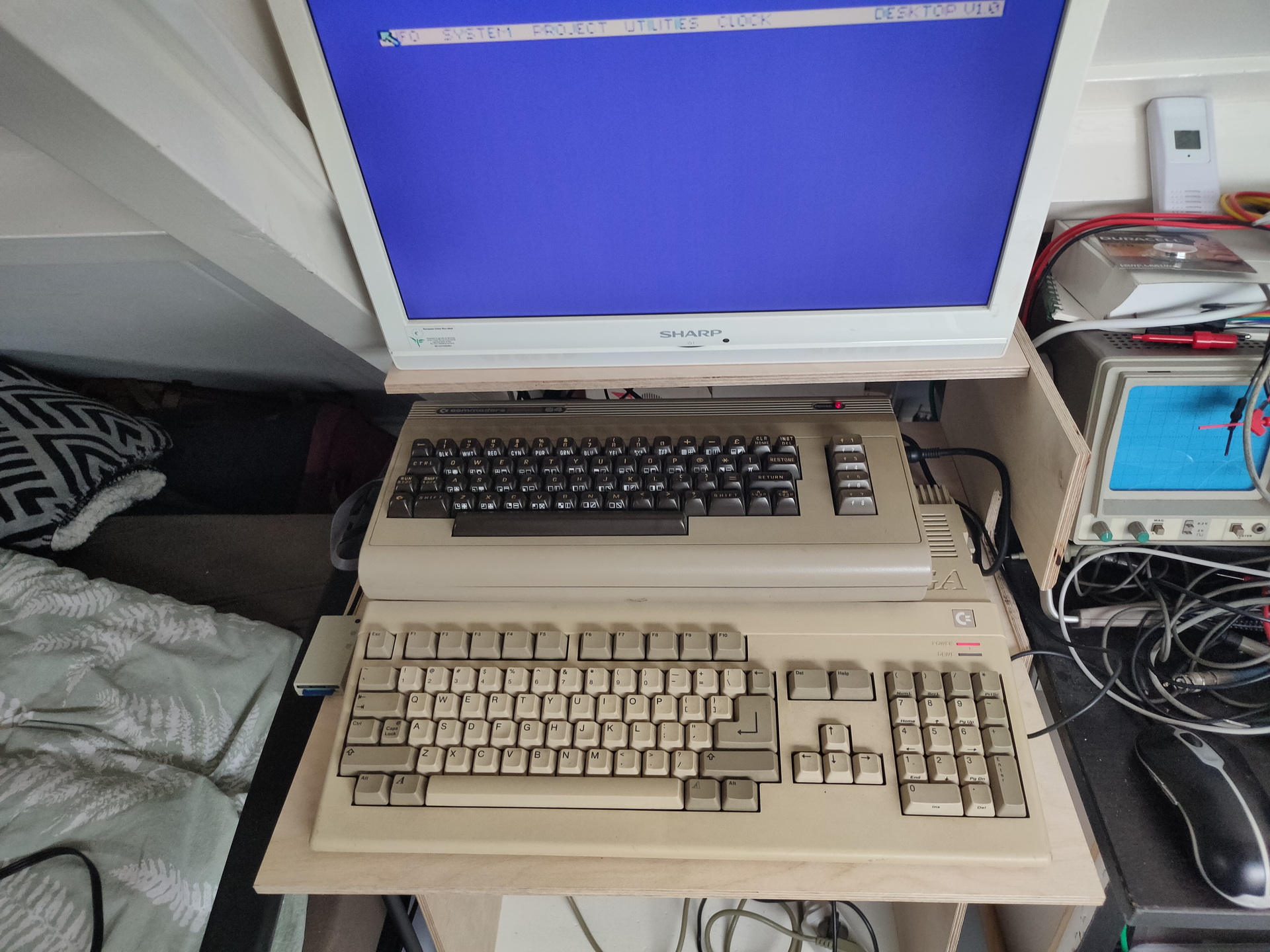
Besides the emulators on my laptop, maybe i’ll bring this little thing (Or a real C64?)
Booting in 4 seconds! Running Vice in 50 or 60 Hz Low latency video! Can emulate cartrides, floppy’s When you connect joysticks or a real C64 keyboard to the GPIO pins it will use that. SID sound using ReSid CRT emulation (look for BMC64 or combian)
I’ve used a basic program on C64 in the past and a Cartridge machinecode monitor in the past. I’ve really forgotten how, what i’ve used and what i’ve done with it. Not nearly as much as my friends at that time. I started with a Vic-20 and played around with machinecode on a 6502. I didn’t have a C64 for many years.
How much funit this!
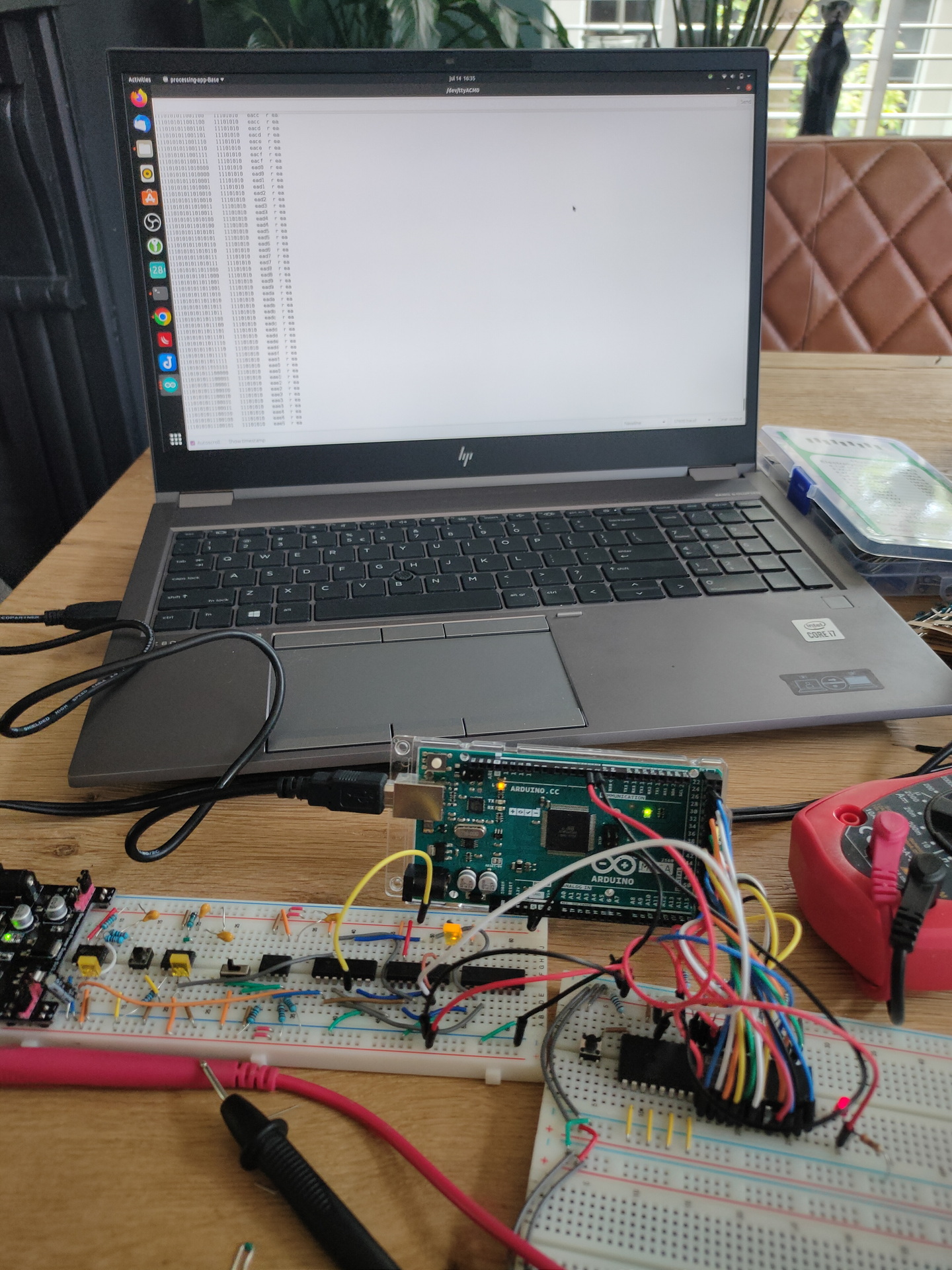
I’ve recently started to build a 6502 computer again, and programming on 65xx again (Generic 6502 and C64). (2022)
Below is my setup on linux, to write assembly code, compiling and running the code in a emulator.
I have installed the Acme compiler and Vice as a emulator. Both can compile/run machinecode for multiple computer emulations. So maybe i can run my old Vic-20 machine code or the few C64 programs i’ve written.
I’ve only made the bash script, the included asm files i copied from someone on the internet. ( Credit lookup )
makeprg bash file:
#!/bin/bash
set -x
f=""
if [ "$2" == "f" ] ; then f="-fullscreen" ; fi
if [ ! -f $1.asm ] ; then
cp template.asm $1.asm
fi
vi $1.asm
acme --cpu 6510 --format cbm --outfile $1.prg $1.asm
if [ ! $? -eq 0 ] ; then exit 1 ; fi
c1541 -format foo,id d64 $1.d64 -write $1.prg
if [ ! $? -eq 0 ] ; then exit 1 ; fi
x64 $f $1.prg
template.asm
!source "basic-boot.asm"

+start_at $0900

; Set background and border to black
ldx #$00
stx bgcol
stx bocol

; Flicker border and background
.loop
  inc bgcol
  inc bocol
  jmp .loop
basic-boot.asm
; A BASIC booter, encodes `10 SYS <address>`.
; Macroified from http://www.pouet.net/topic.php?which=6541

!source "constants.asm"

!macro start_at .address {
  * = basic
  !byte $0c,$08,$00,$00,$9e
  !if .address >= 10000 { !byte 48 + ((.address / 10000) % 10) }
  !if .address >=  1000 { !byte 48 + ((.address /  1000) % 10) }
  !if .address >=   100 { !byte 48 + ((.address /   100) % 10) }
  !if .address >=    10 { !byte 48 + ((.address /    10) % 10) }
  !byte $30 + (.address % 10), $00, $00, $00
  * = .address
}

; A cooler example is to write
;
;   10 SYS <address>: REM <backspaces>Your comment
;
; When the user types LIST, he will just see
;
;   10 Your comment
;
; but still be able to run it.
; For this, see http://codebase64.org/doku.php?id=base:acme-macro-tu
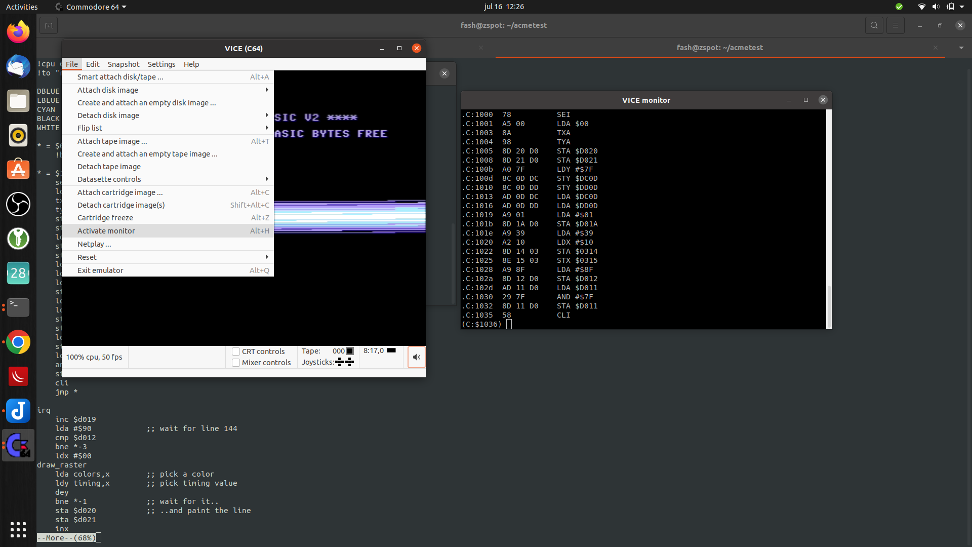
When running above bash script. it will open the file if it exists, else it will take a template file. After opening it with vi, and editing it, it starts a the compiler and creates a C64 d64 disk. This is going to be autorun/started with the VIce emulator. Appending -f to the bash script will start it in fullscreen mode. ./makeprg myawesomedemo.asm -f
Below it is running without the fullscreen option. but is shows how to start the interactive monitor in vice.
Update: 20220721 .. VIA chip installed Update: 20220801 .. changed layout, addressing and added rom, see below post.
Such a influencial little processor … Apple, Vic-20, C64 (with modifications), PET, BBC Micro, Oric, Atari and Nintendo.
Another (big brother) influencial CPU is the 68000. (Amiga/Atari ST/ Macintosh/Sinclair)
I’ve made a 680x computer in the past, and i want to make another one.
This one will be based on a 6502, because i used to program on this cpu when i got my Vic-20.
Goals of this project:
6502 Cpu
Memory and Rom
Rom must contain a good machinecode monitor
Adjustable clock
Now using Ben Eatons clock diagram, but i will move this to a programmable arduino, with a display which shows the clock rate
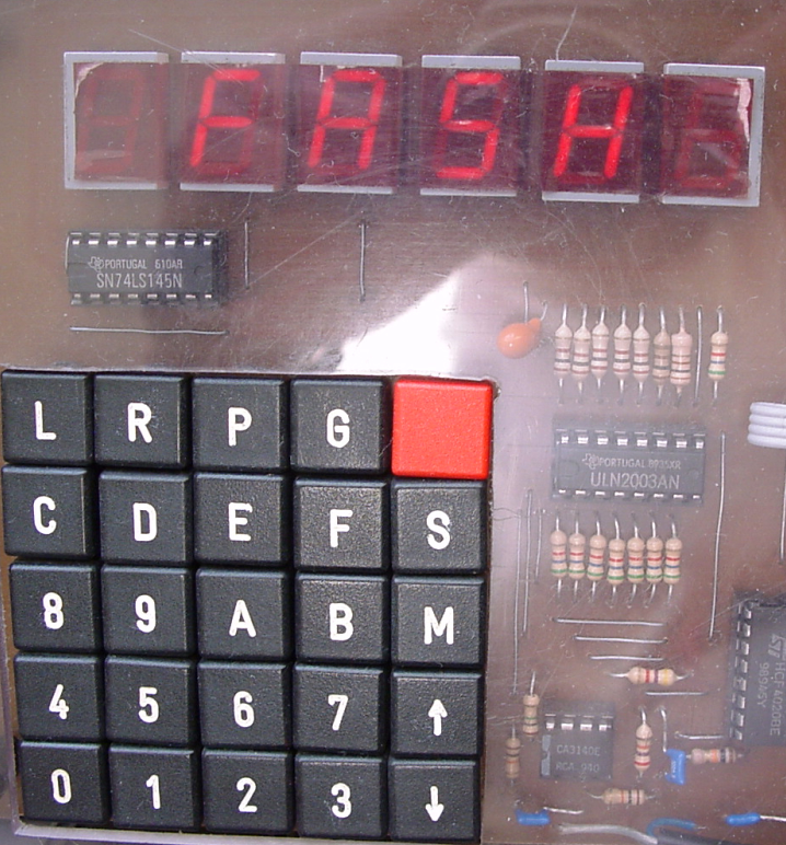
Hex keyboard ro program the machine, just like picture below
Display which was a resolution of at least 640×480
It will be a slow screen, character printing and a gfx mode?
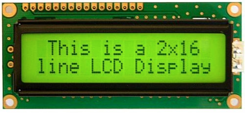
First probably a SPLC780 HD44780, so i can enter/edit machine code.
Hopefully using a SID chip
Hardware monitoring of the address and data lines like movie below
Programming via serial/usb, by halting the 6502 cpu and pushing data into memory or fake-eprom with a arduino
Save/restore by modifying memory
Small
Example of Hex keyboard
Update 20220721
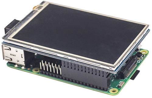
Via chip is on the board. For now i’m using a old display, like this one
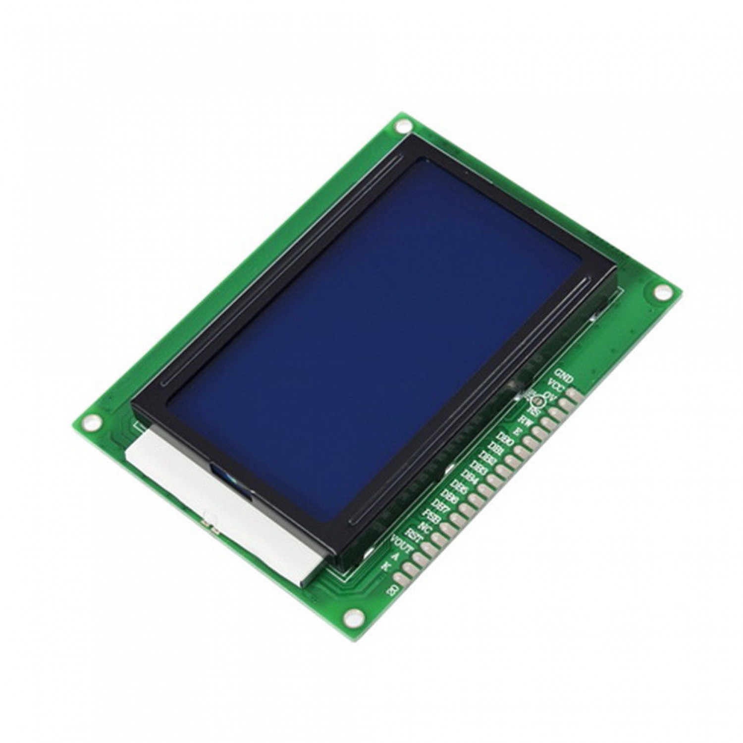
I was planning to use this one
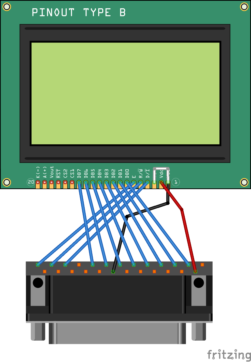
The graphic capable 12864 display (128 x 64 pixels)
I will reuse the schematics i’ve used for the 680x computer. (Posted above)
Update: 20220801
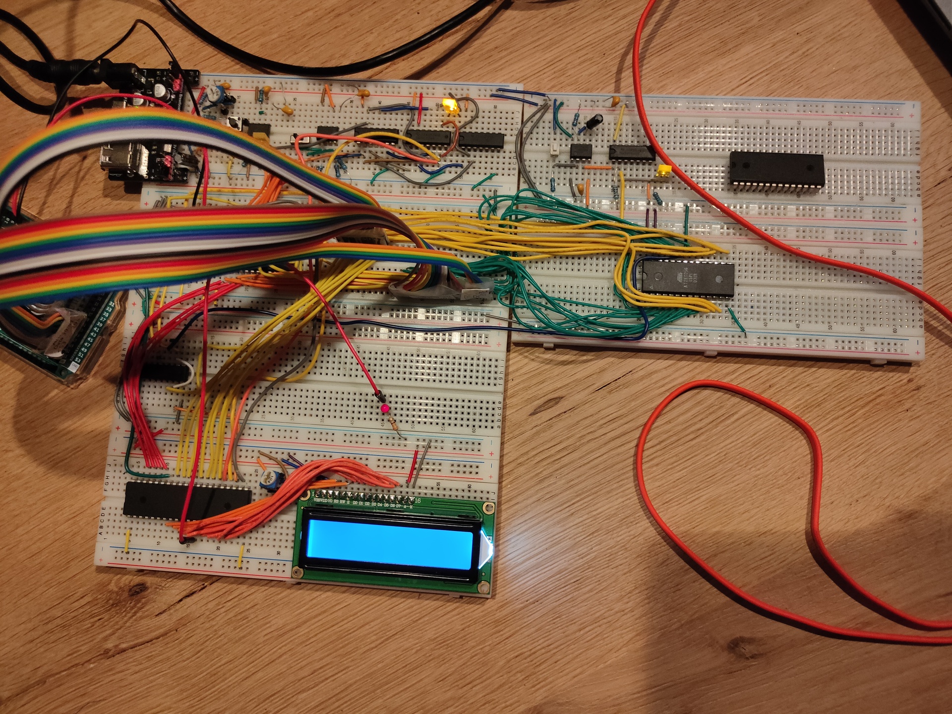
Added ROM, and changed layout. Every breadboard has a function now.
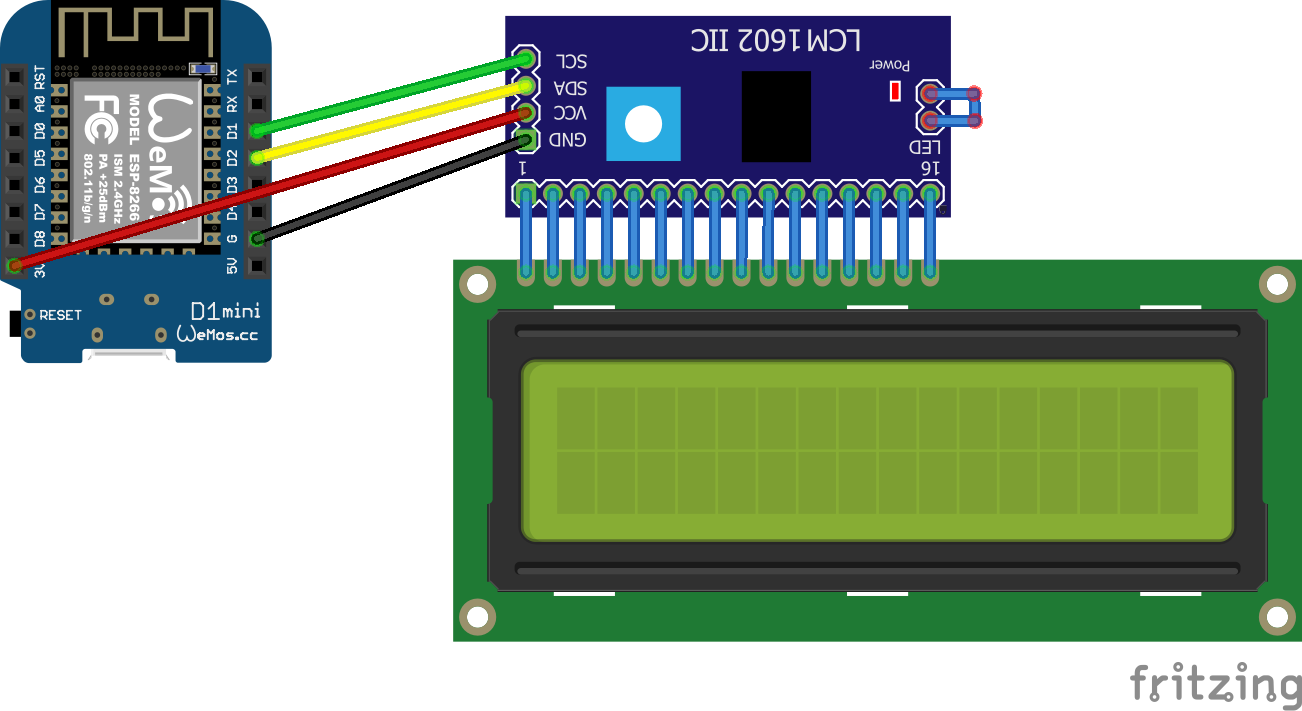
Upper left, Ben’s Clock module (this is going to be changed to a arduino with display which shows frequency) Upper right, power-on reset (Reused part of C64 schematic) Second row left, the 6502 On the right the ROM, RAM i also going to install here. 3rd Row, Address decoding, this is going to be a dynamic setup using dip switches and a eeprom for decoding (i know, this kind of decoding is slow, but i don’t need speed), on the right probably the hex keyboard with its own 6522. 4rd row left, a temporary display 16X2 connected via a 6522. Here i want to have a graphical display. 4rd row right (not started this part yet) a sound device. SID or a Yamaha sound chip i still have.
Below some examples and connection diagrams to control displays. More code and complete schematics will be added on this page or on a separate projects page.
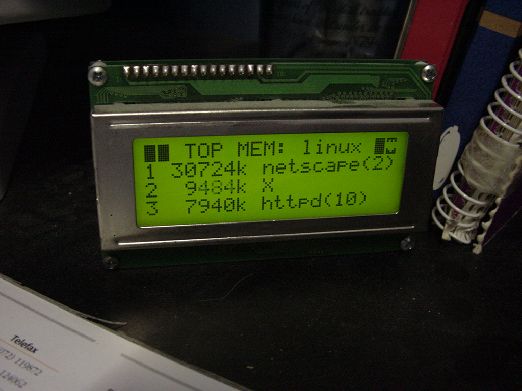
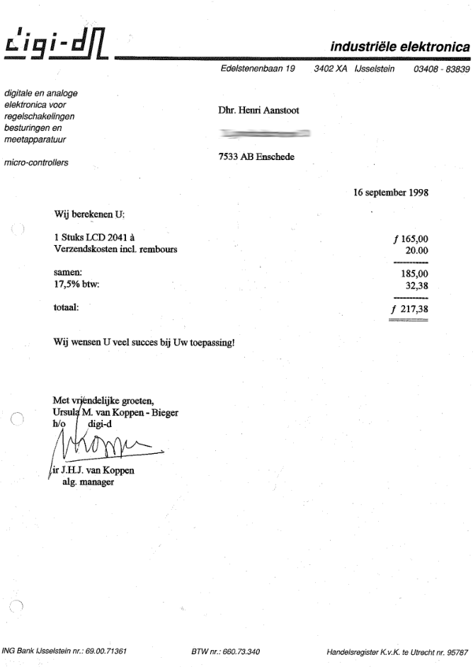
UPDATE 20230119 Cost of 20×4 display in 1998
LCD
I’ve used a LCD display like this (HITACHI HD44780) on my PC in the 90s, and also written code to use this as a monitoring device on my amiga.
On Linux i used LcdProc – This module also was equiped with a serial connector
Now (2023) it is 8 euros! When bought now fl to euro 98 Euro or 107 $
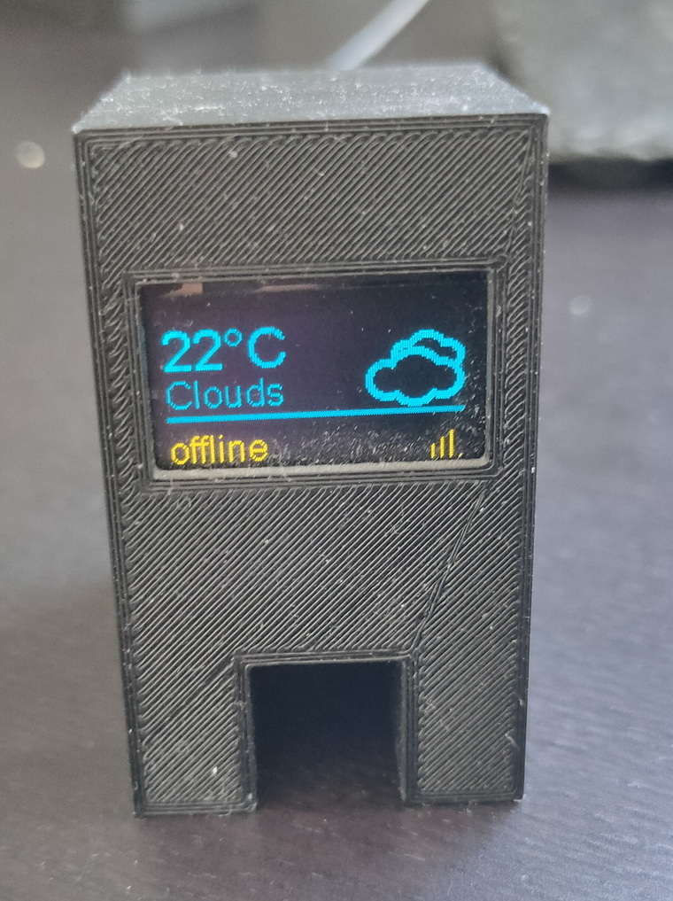
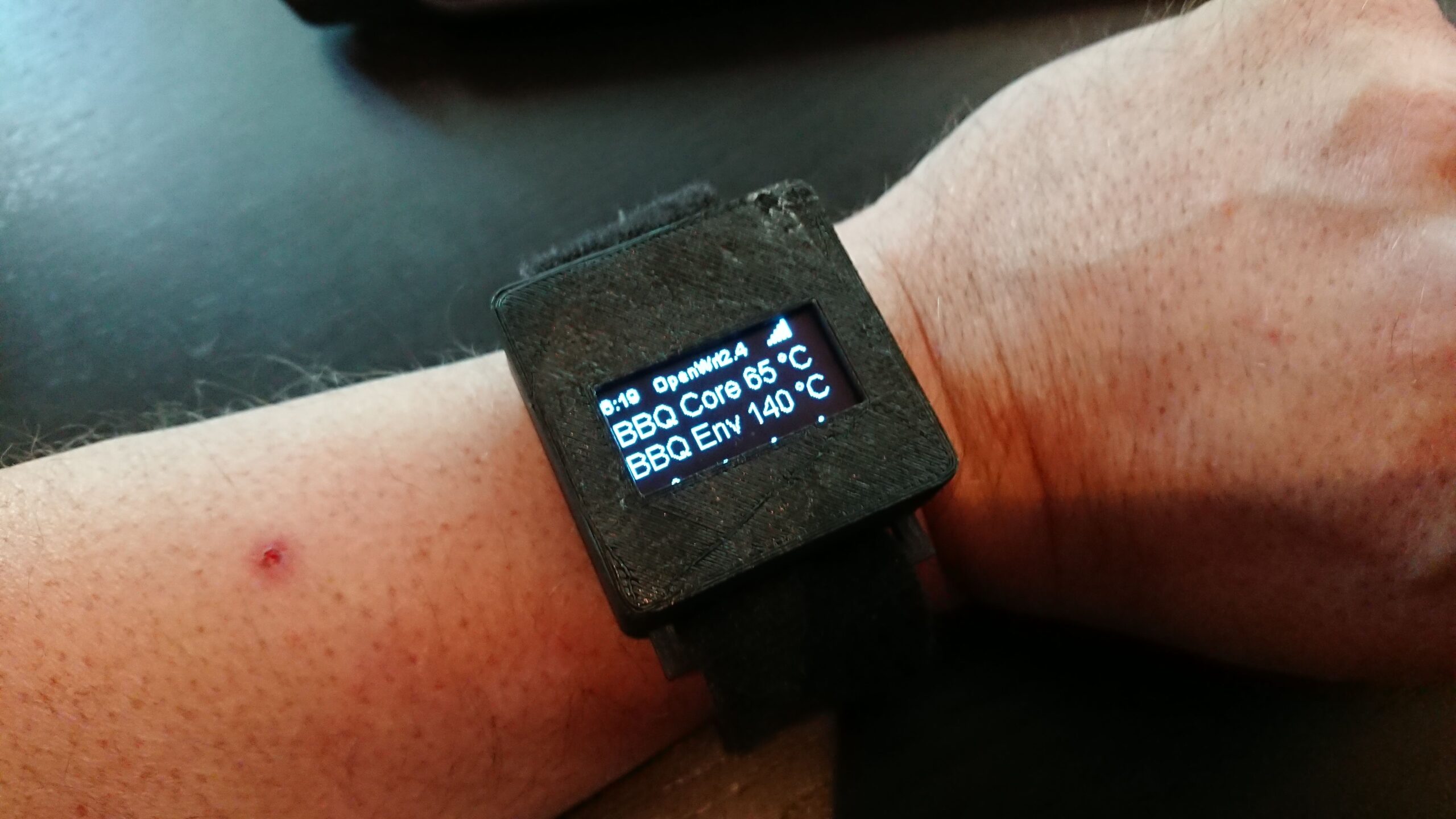
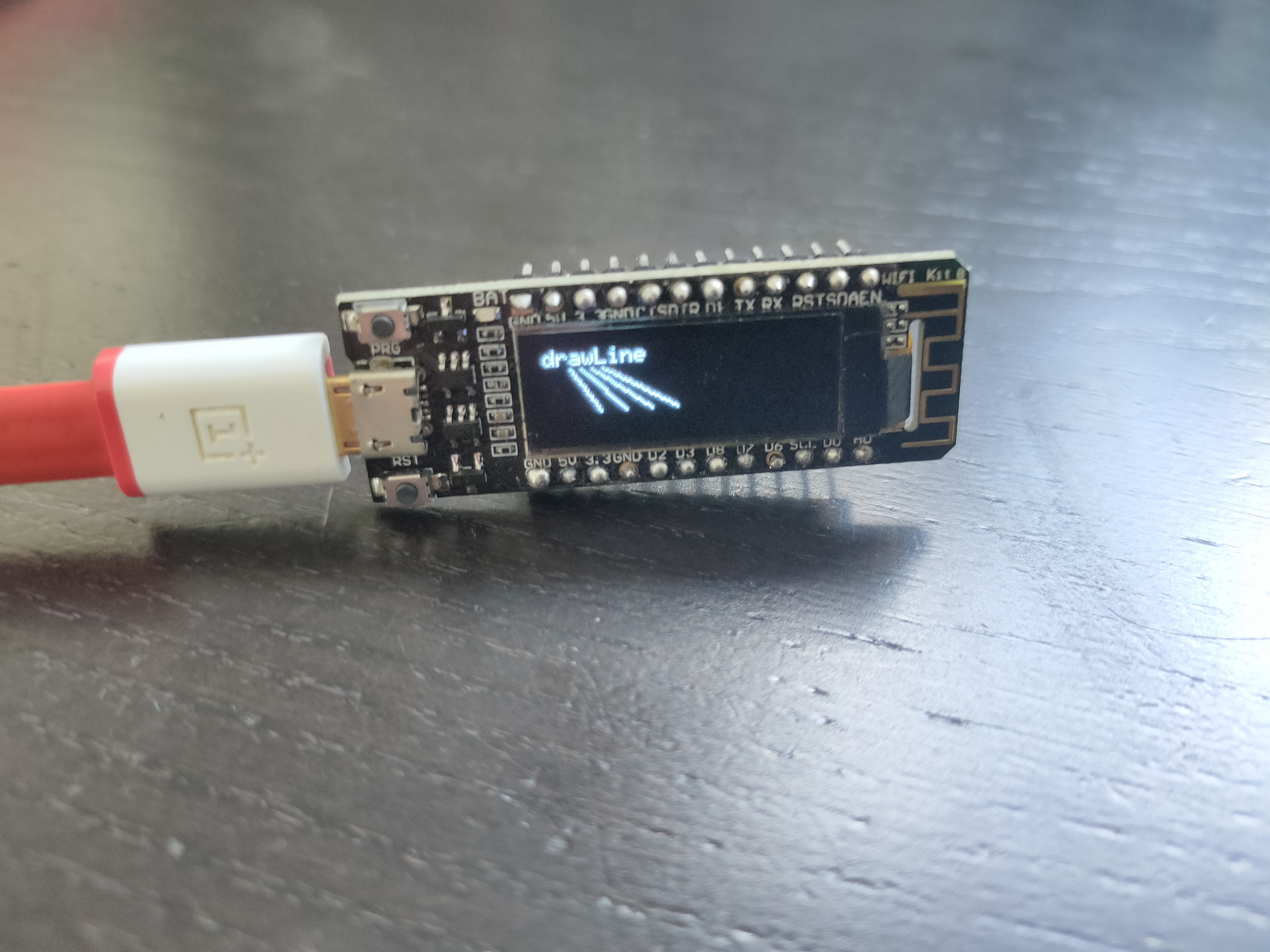
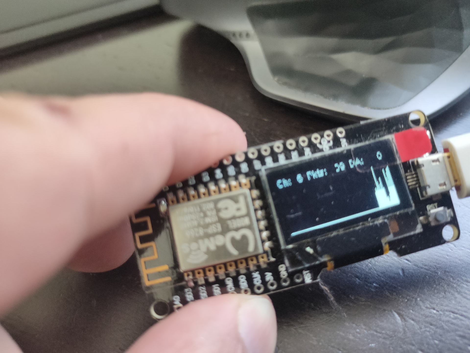
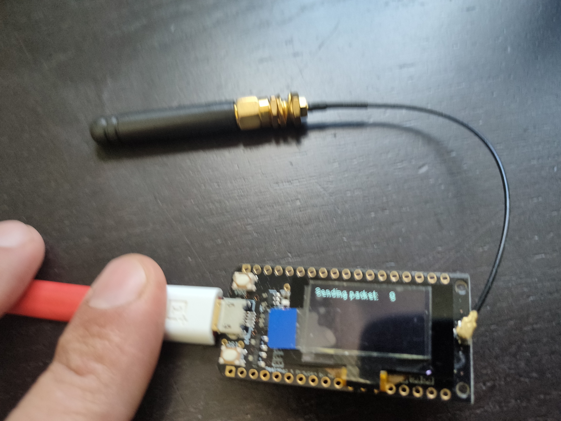
Some arduino’s have embedded displays like those i’ve used for a Lora project.
No usedWifi packet monitorLora test
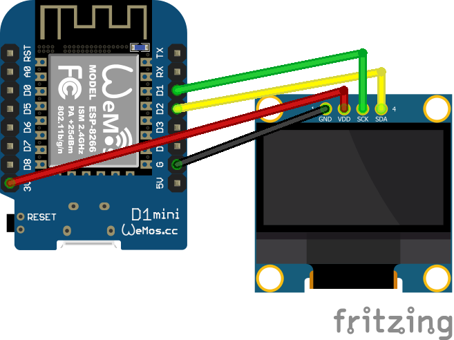
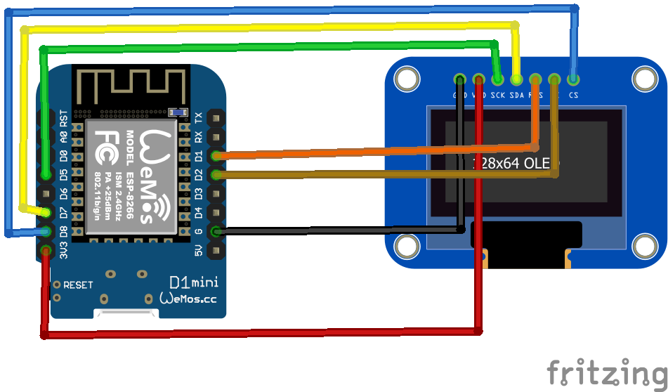
Other means of connecting : SPI
SPI connected display
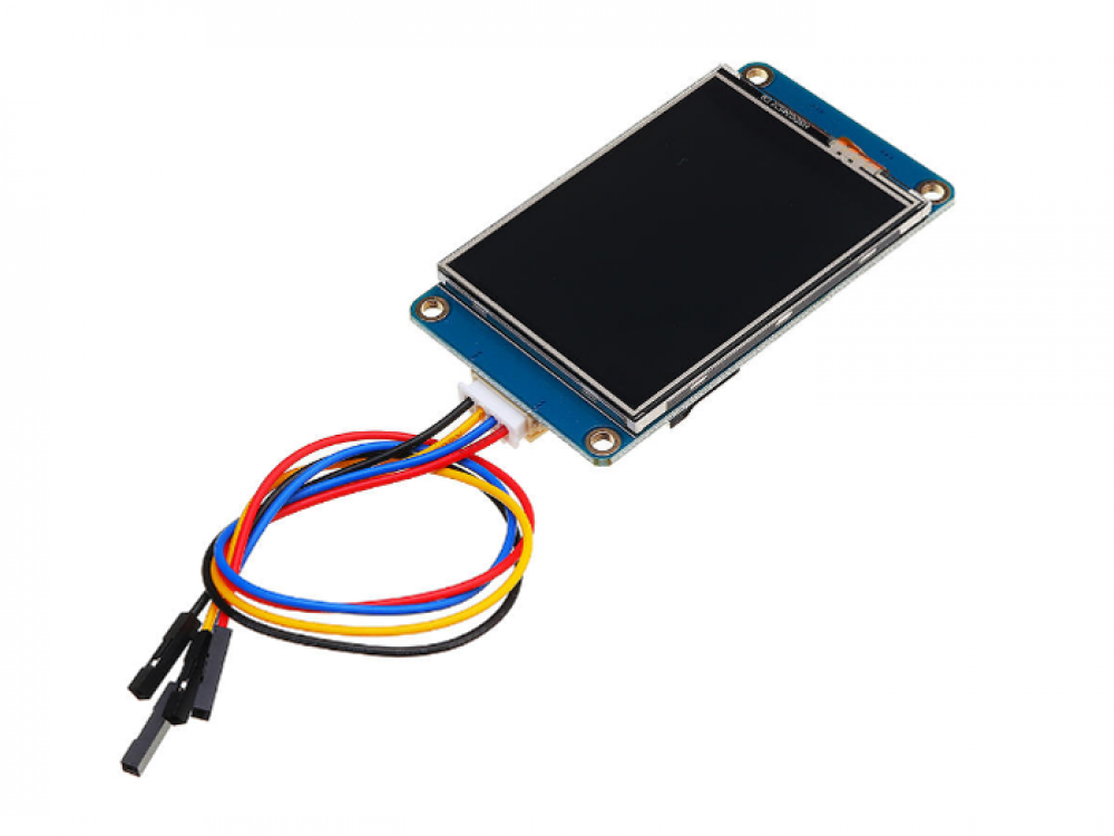
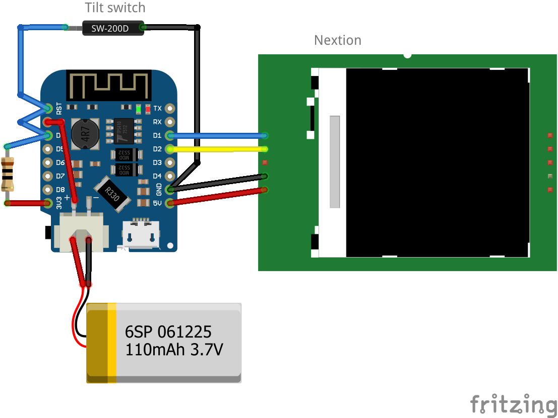
Nextion
Nextion is a Human Machine Interface (HMI) solution combining an onboard processor and memory touch display with Nextion Editor software for HMI GUI project development.
Using the Nextion Editor software, you can quickly develop the HMI GUI by drag-and-drop components (graphics, text, button, slider, etc.) and ASCII text-based instructions for coding how components interact on the display side.
Nextion HMI display connects to peripheral MCU via TTL Serial (5V, TX, RX, GND) to provide event notifications that peripheral MCU can act on, the peripheral MCU can easily update progress, and status back to Nextion display utilizing simple ASCII text-based instructions.
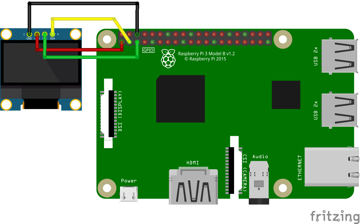
edit cmdline.txt
add "fbcon=map:10 fbcon=font:ProFont6x11 logo.nologo"
at the end
edit config.txt
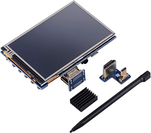
add between custom comments at the bottom
dtoverlay=piscreen,speed=24000000,rotate=90
# Or check http://www.lcdwiki.com/3.5inch_RPi_Display
Above display’s i’ve used for Picore Players and the Lidar POC
To try: Getting above display running with a arduino https://github.com/PaulStoffregen/XPT2046_Touchscreen
Raspberry HDMI display
Easiest of them all, just connect with HDMI, there is a adaptor for hdmi-hdmi (versions 1,2,3) and hdmi-mini-hdmi for RPi4 variants.
Epaper and 7-Segment displays
Other means of displaying information are for example
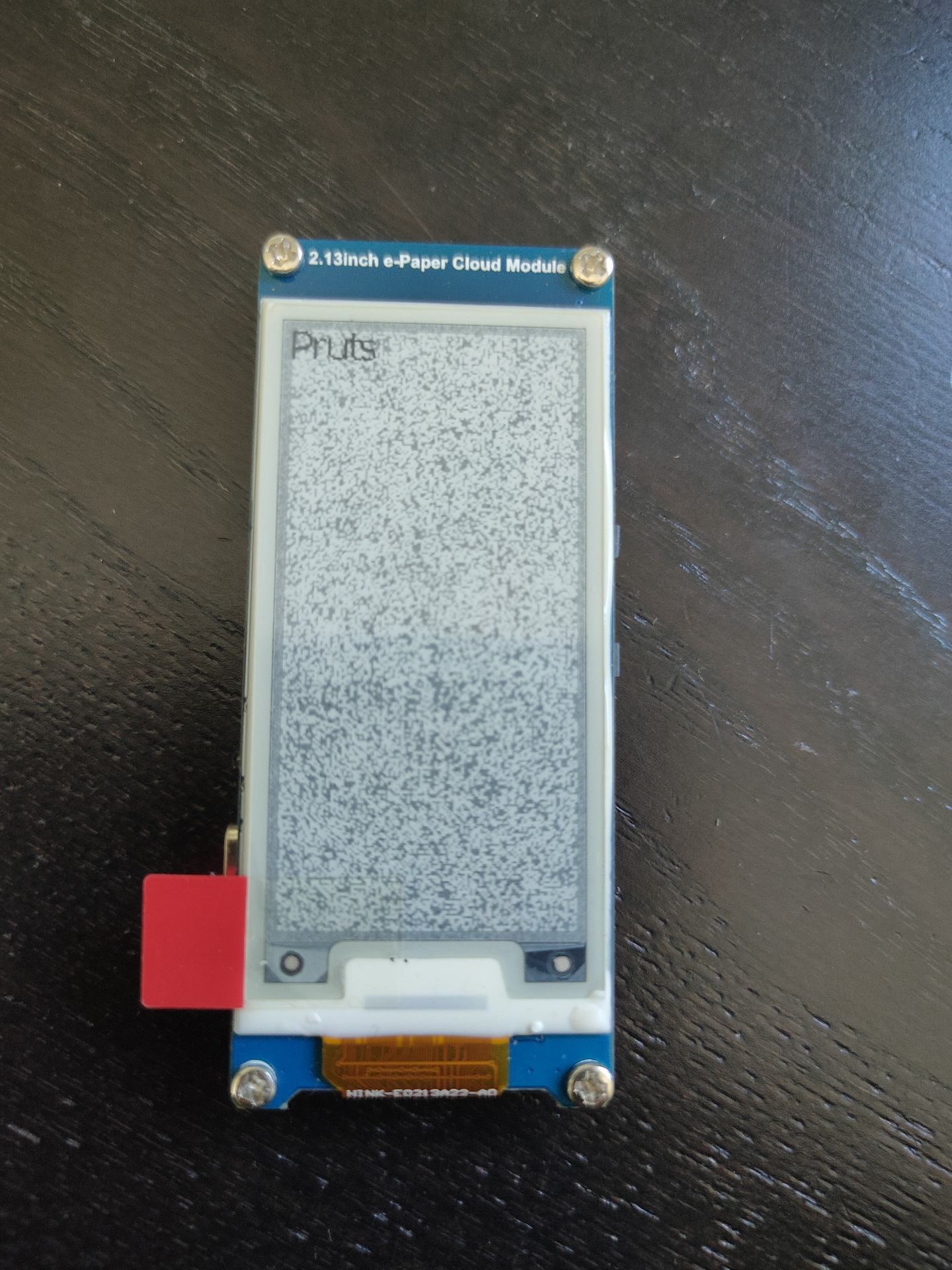
Epaper
ESP with epaper module, disconnected power for a while, artifacts appear.
7 Segment displays
I used a lot of 7-Segment display’s in the past. They look cool and are hardcore.
My homebrew computer uses this
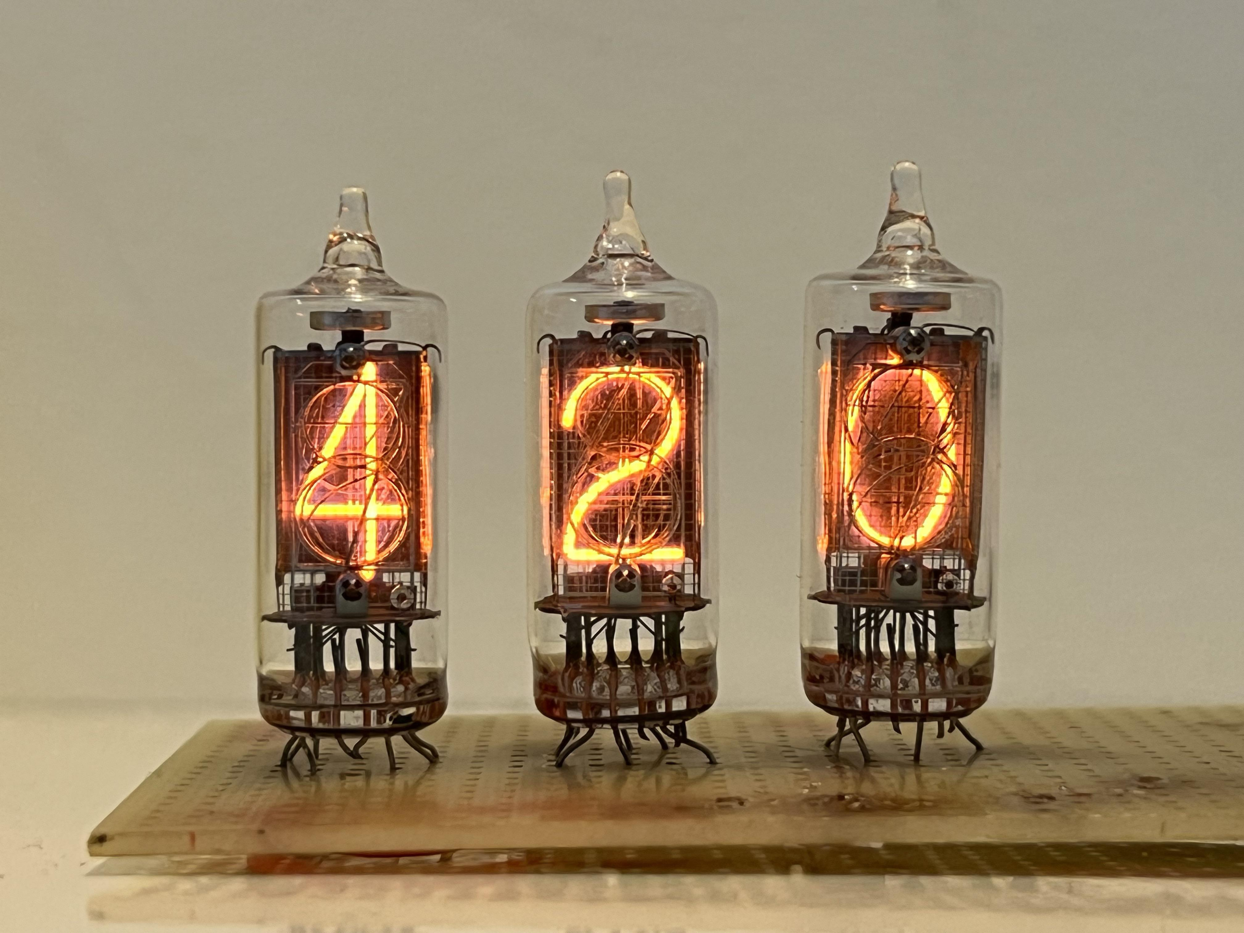
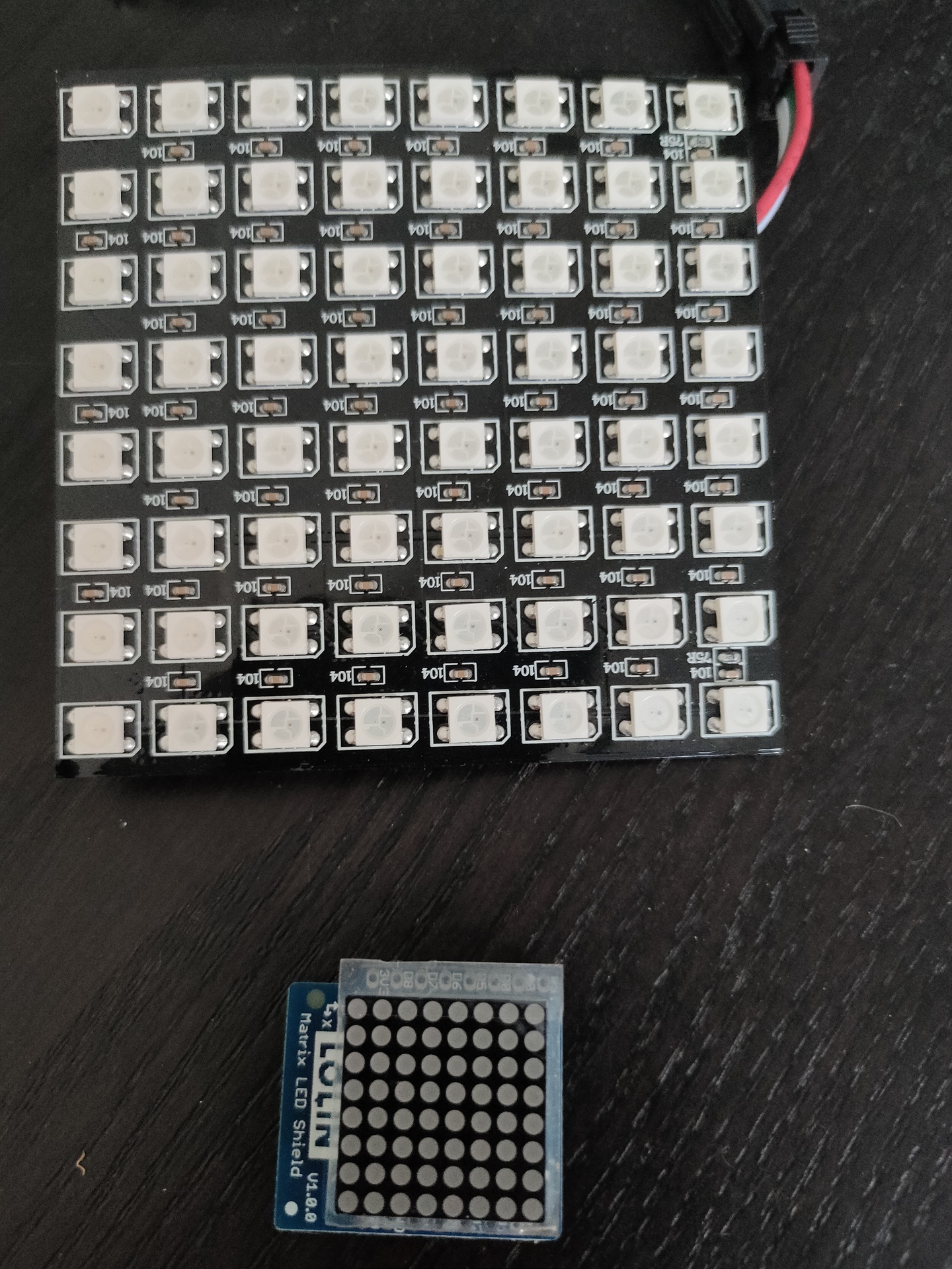
Nixie tubes!
And there are https://en.wikipedia.org/wiki/Nixie_tube .. I’ve never had those
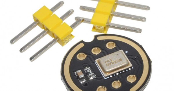
Above bigger 2D display i used with Wled and a digital microphone, so its sound reactive. The lower part i got in recently .
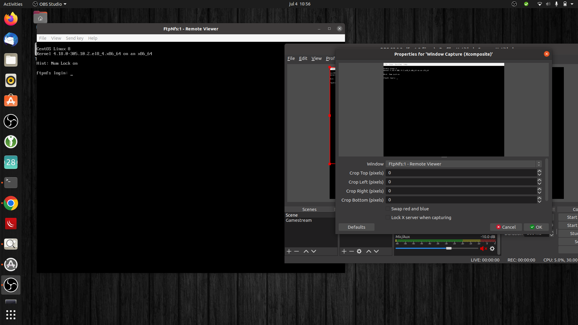
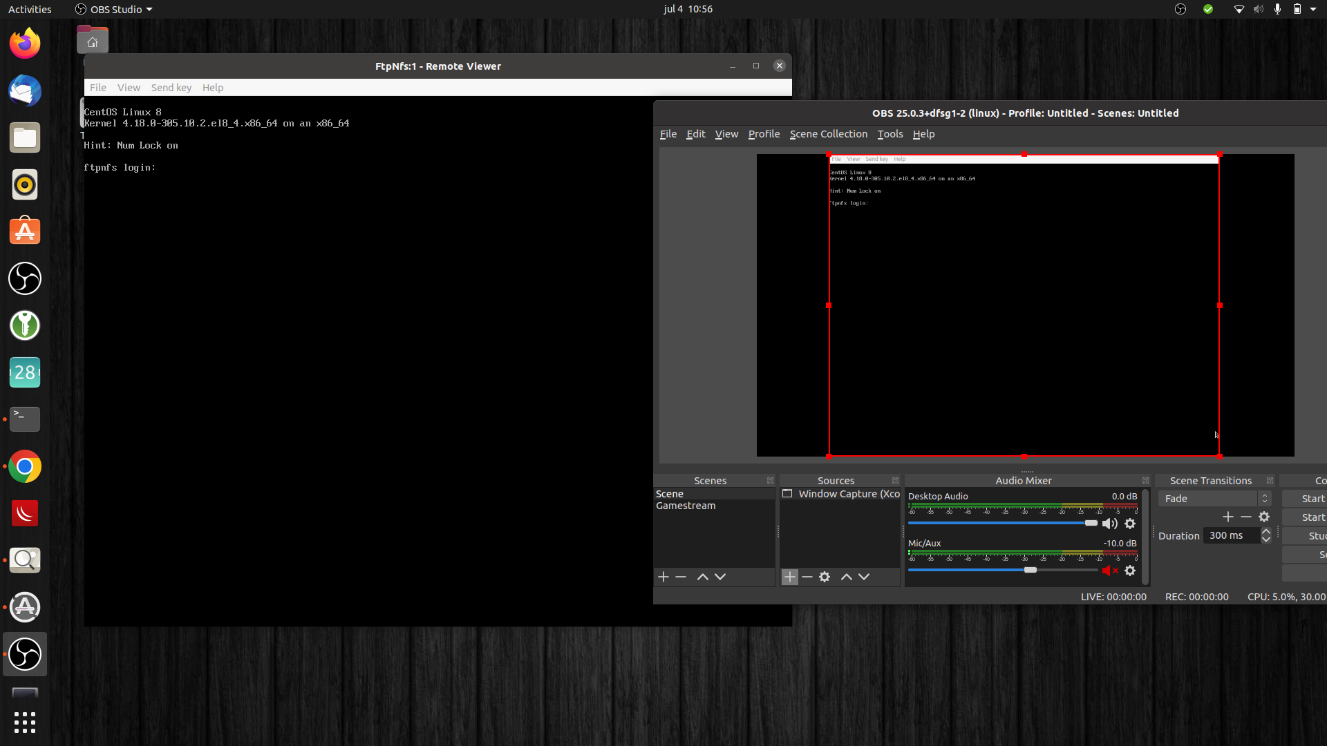
While you can use screencapture to record virtual machines, to real machines it is a different story.
Virtual machines running locally or remote can be accessed with spice/vnc or rdesktop. So you have a window displaying the remote screen, which you can capture using window capture.
There are also emulators which you can window-capture. But i want the real thing when available. Emulators give a too crisp screen output. And you want to have the real SID chip sound.
Hardware capturing:
Recording Virtual machines
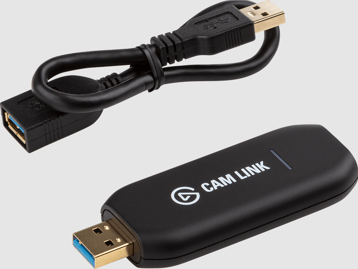
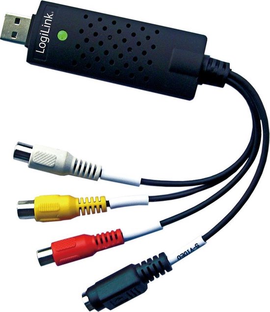
I’ve got two capturing usb sticks:
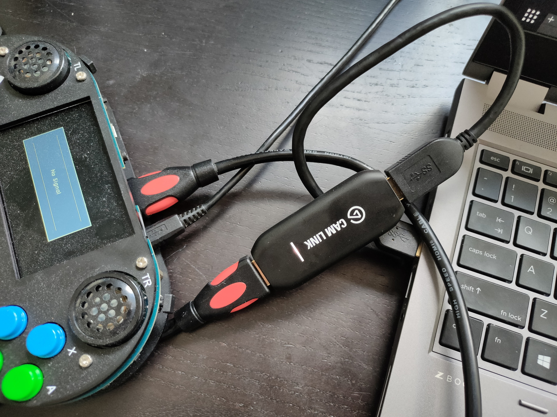
Camlink 4K for hdmi capturing (Which i use mainly for my nikon)
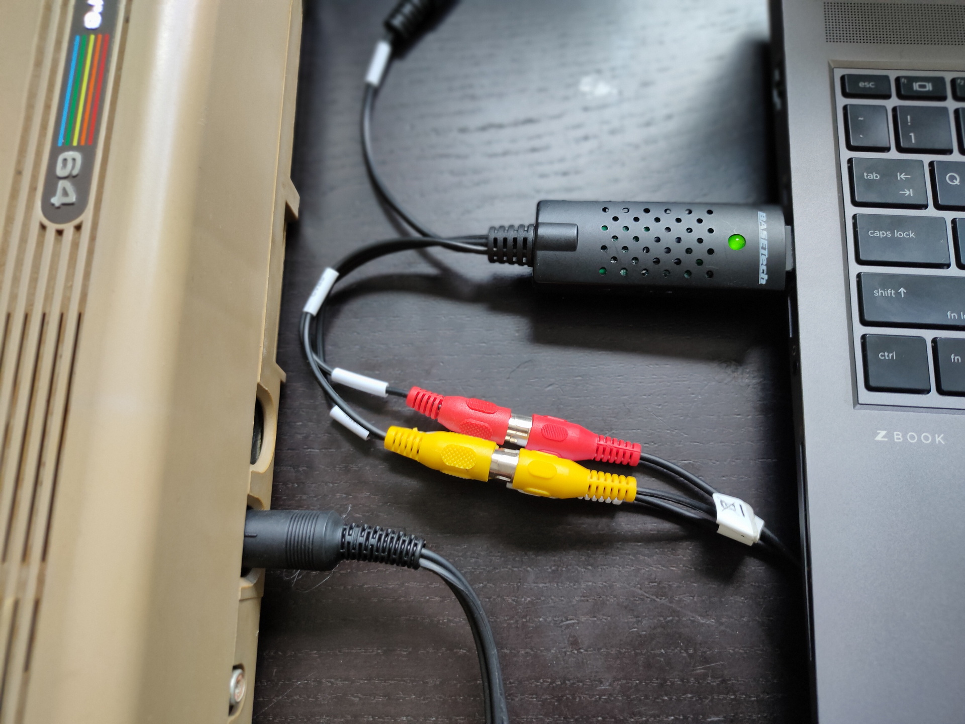
Basetech BR116 RCA and S-Video capture (NTSC 720 x 480 , 30 FPS/PAL 720 x 576 , 25 FPS)
Devices and recording:
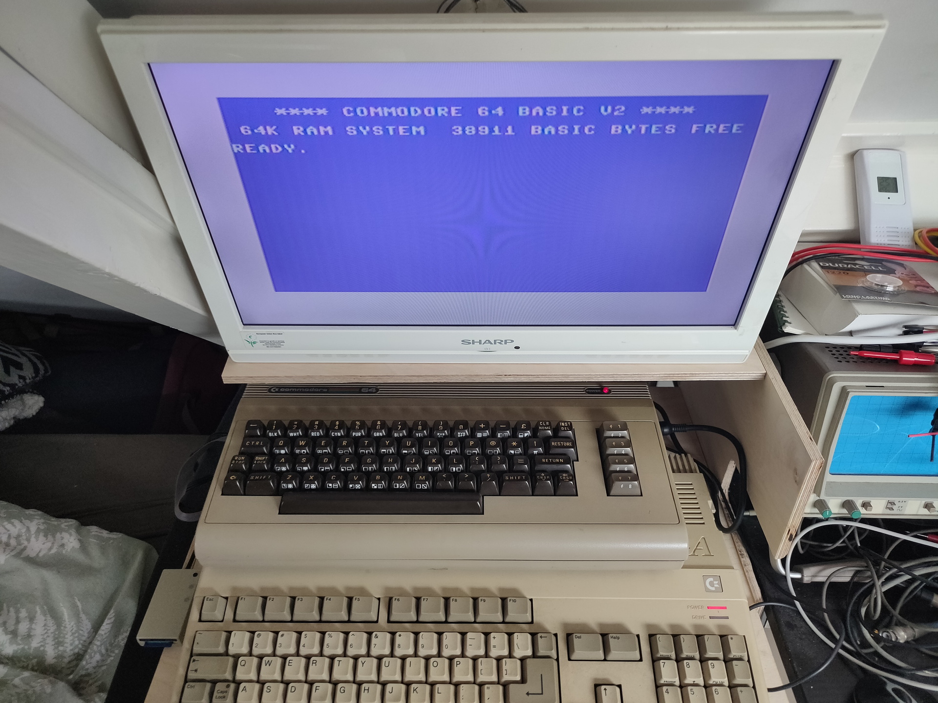
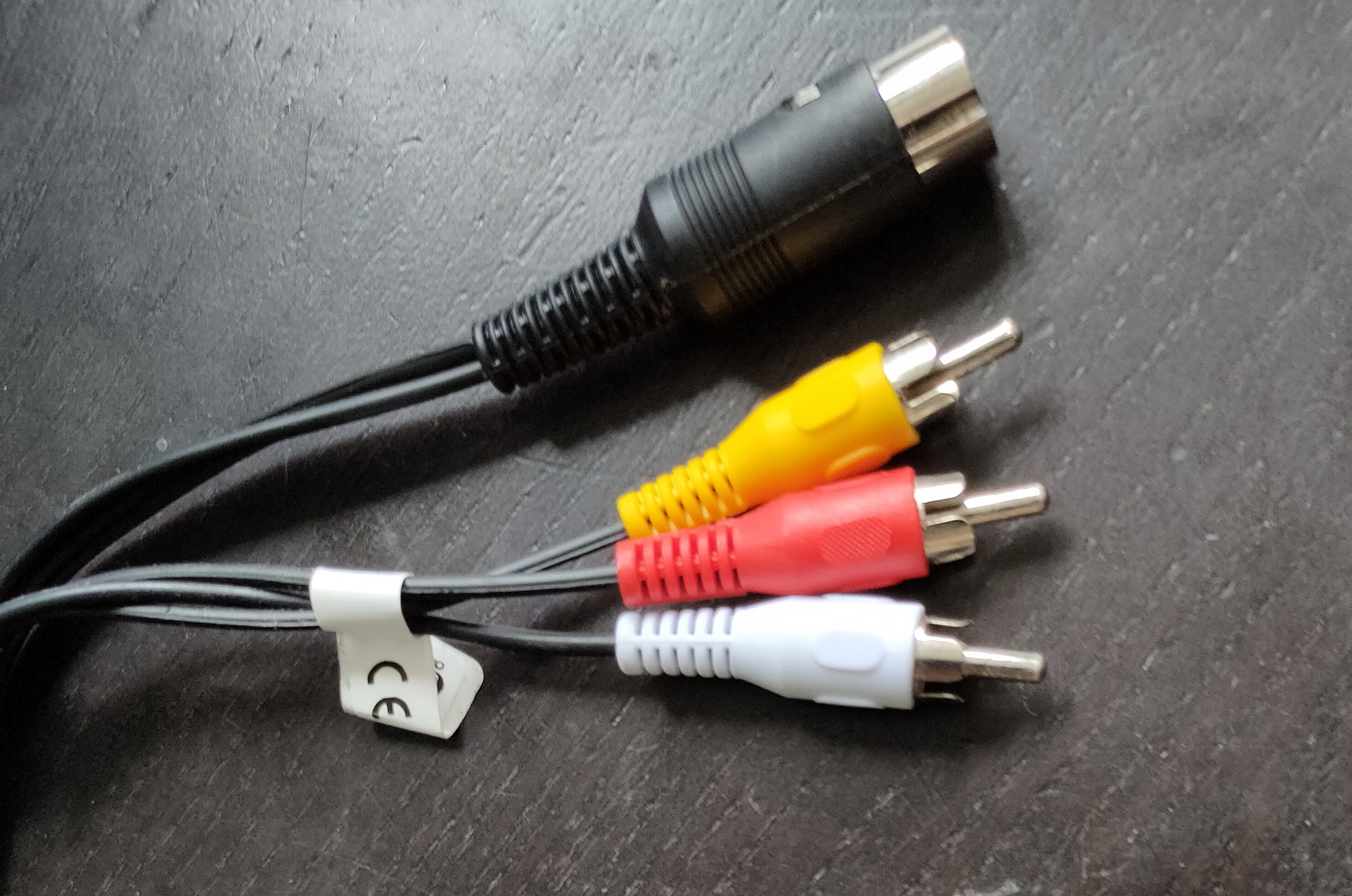
C64 – Use Basetech, and the DIN to RCA cable
Vic-20 – same as above
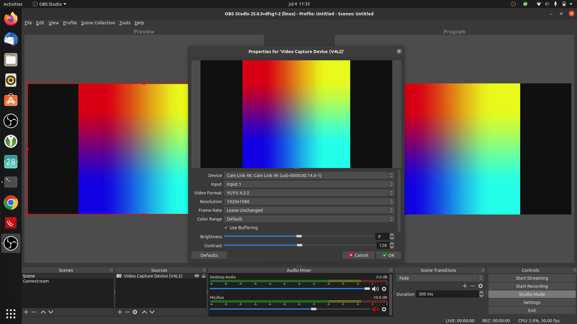
Raspberry – Use a HDMI and Camlink
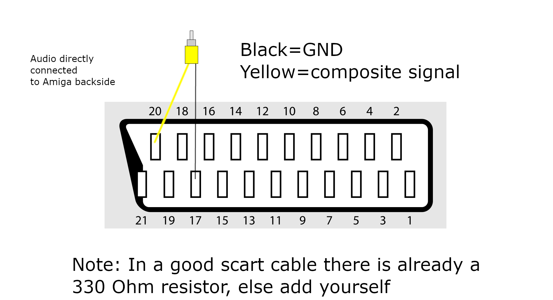
Amiga – I use the basetech and grab the composite signal from the Scart connector, another solution is to use a A520 Modulator, which has Composite out. (There are schematics on the internet to connect hdmi to your amiga)
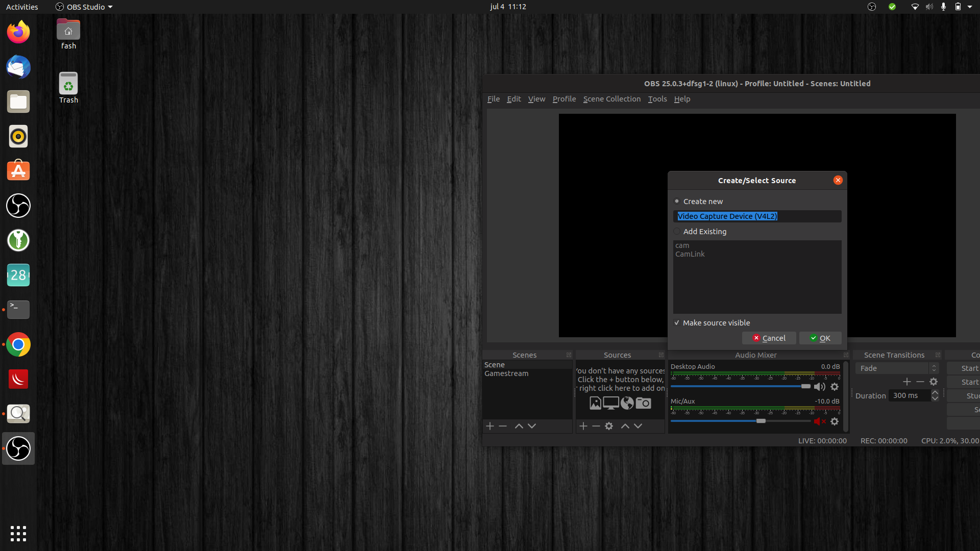
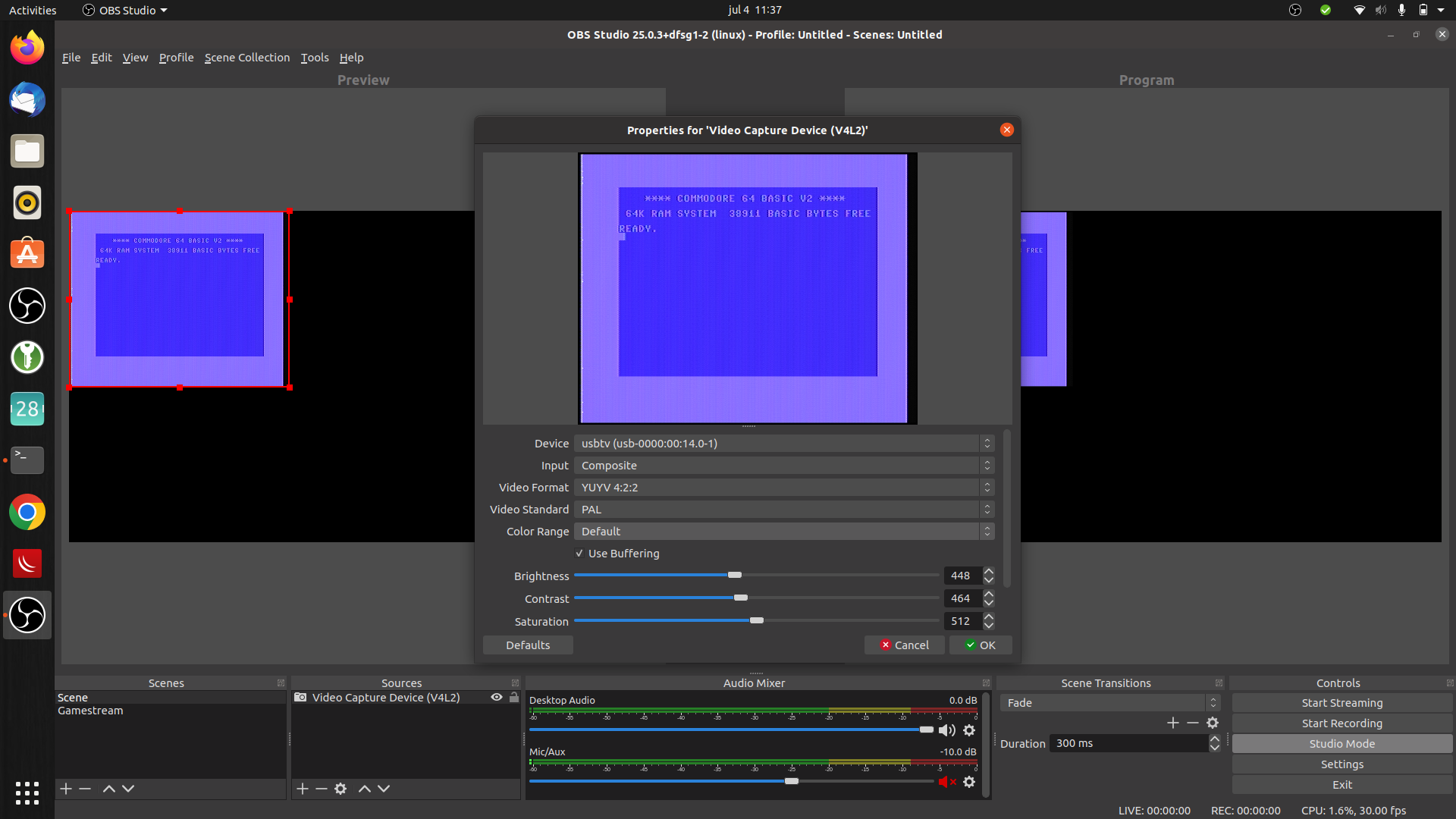
C64 DIN RCA cableC64 connectedAdd video capture deviceRaspberry HDMIRaspberry bootingC64 settings
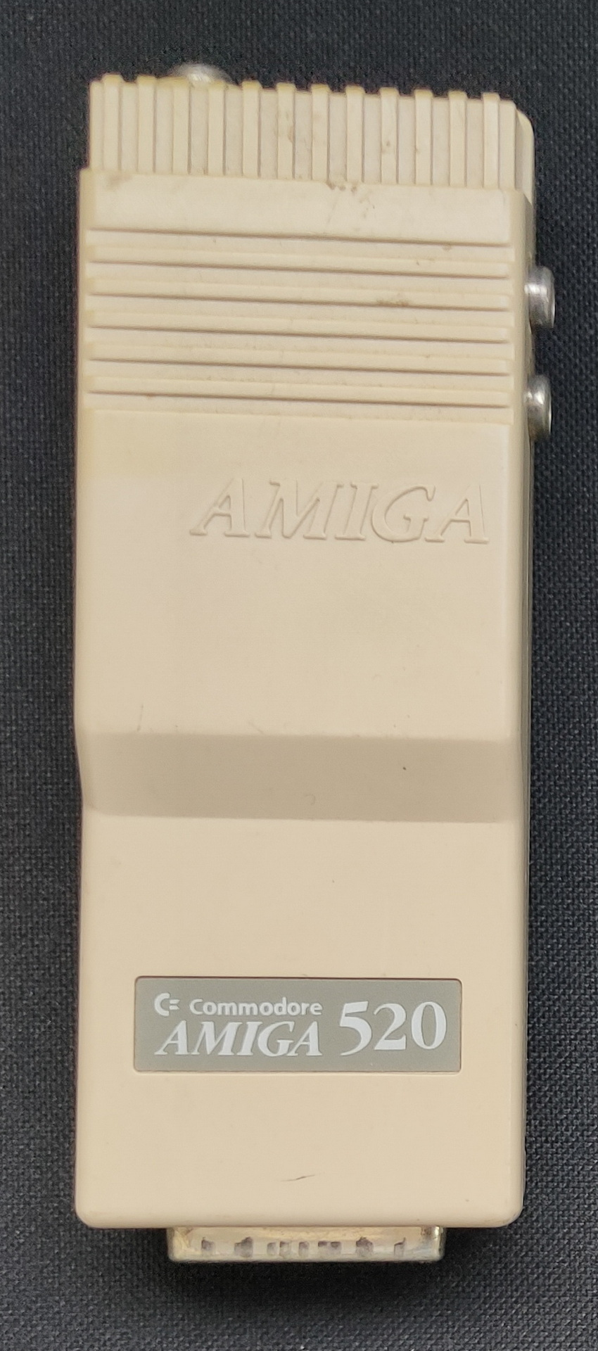
Amiga A520 Modulator
The 520 Modulator connects to the amiga using a DB23 connector, and a Y cable for the 2 rca audio jacks. It outputs a composite video signal, and RF modulated signal to connect to a old Tube/Crt monitor
How i connected my amigaSubD23 to Scart plus audio
When recording video from those screens, i configure my OBS file format to MP4. This makes it easier to embed into websites. Only downside on writing to MP4 instead of mkv is the fact that the file probably isn’t recoverable when something crashes.
Audio capturing :
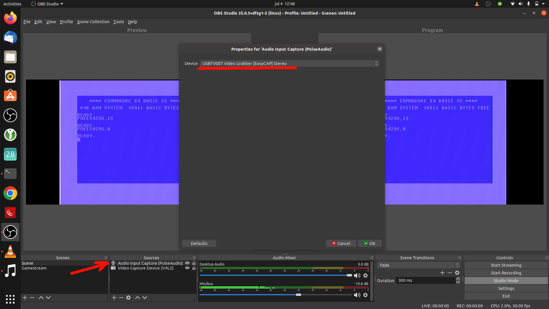
When capturing your movie don’t forget to add a audio source to your OBS sources. Use Audio input capture, or you can use Audio output capture when sound is playing by your system.
Demo a friend made using a demomaker (Music starts half way)
Flightsim on a Amiga (See more on flightsims)C64 Hellraiser (part 1) no de-comb/de-interlace filter
Note: check your output/cables https://www.youtube.com/watch?v=entQosOLjEI
"If something is worth doing, it's worth overdoing."