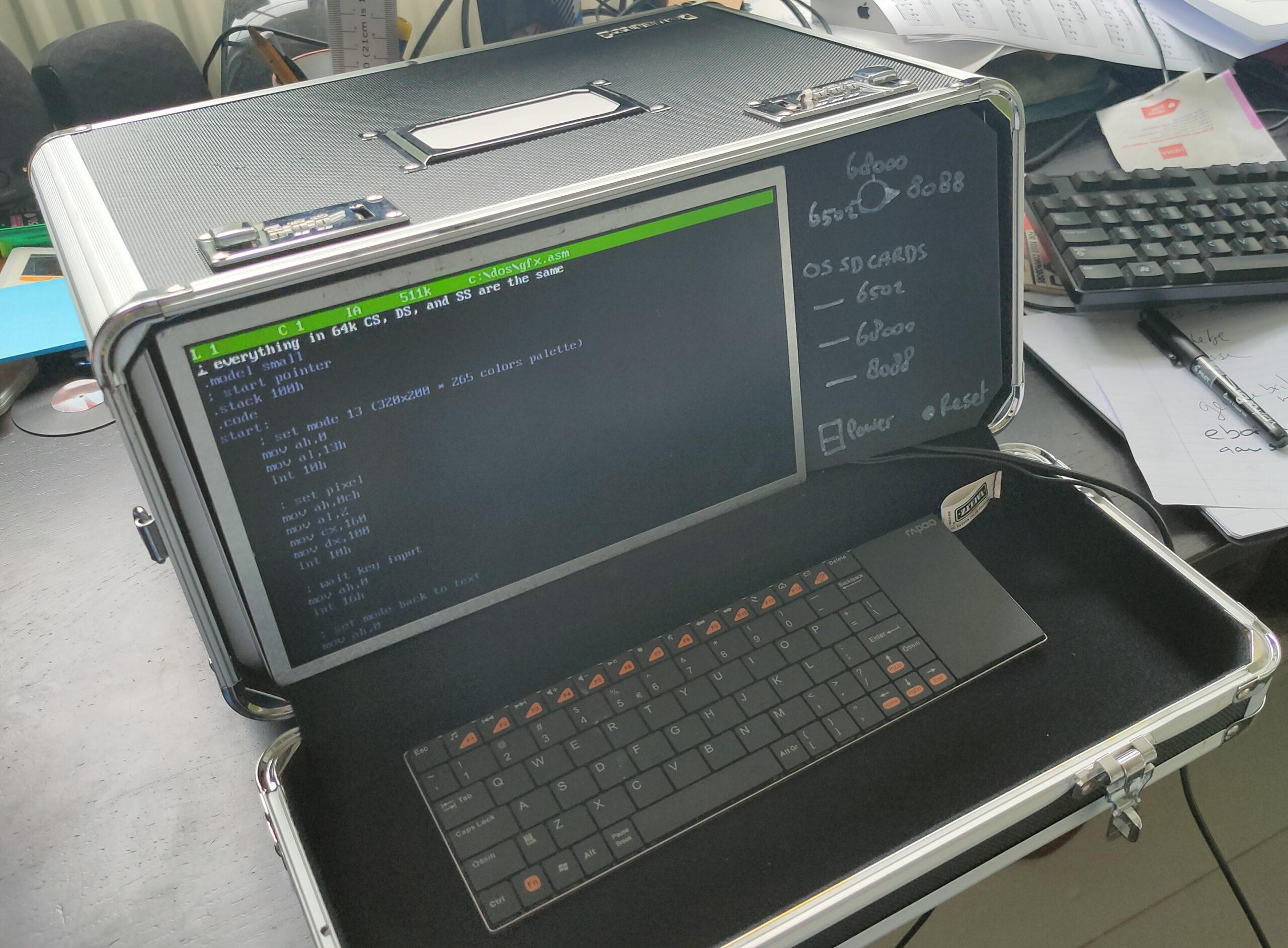
Test picture of a multiprocessor computer setup. Using buttons on the right, I want the possibility to change between systems and keyboard settings. Also, multiple software/OS slots for SDCards will be on the right.
Mockup using a laptop display (eeepc) a bought display controller and a pi2 with Faux86
The lid containing the keyboard has a handle!
After laser cutting a nice front, it could become a nice road warrior hacking station.
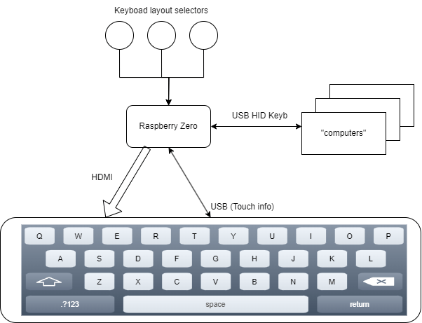
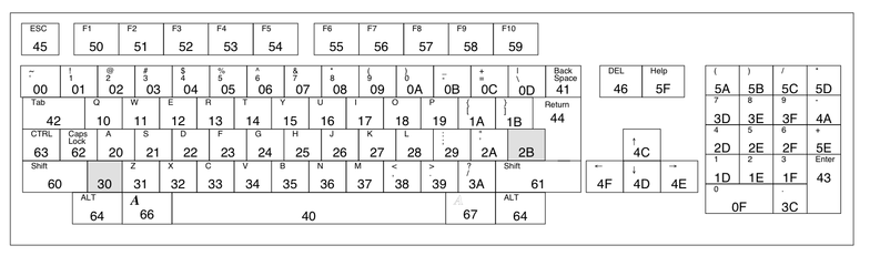
I’m going to replace the wireless keyboard, probably with a touch display and a programmable layout for keyboards. Something like below
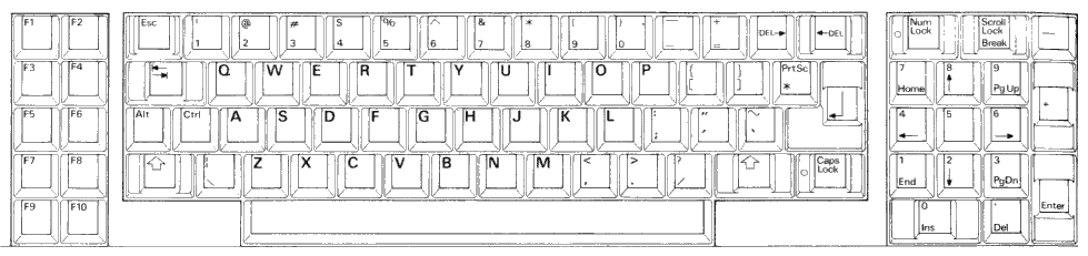
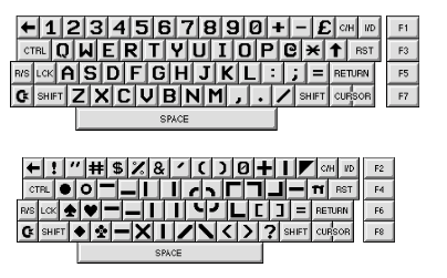
Some layouts:
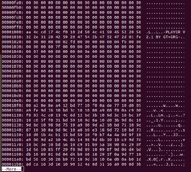
8088650268000
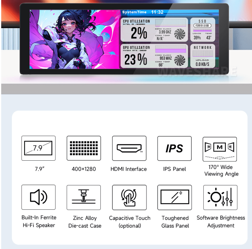
I’ll probably buy this one from waveshare
Info about Faux86
8086/8088, V20, 80186 and limited 286 instruction set.
Configurable CPU speeds from 5Mhz up to 100Mhz.
Custom Hardware BIOS’s supported.
Supports bootable disk images in .img and .raw file format.
CGA / EGA / VGA Colour Video emulation, with most modes supported.
PC Speaker, Adlib, Soundblaster and Disney SoundSource.
Re-learning the little I knew (I never had a c64 as a kid). Back to basics, welll machine code I mean.
Programming a little demo using acme. Split screen bitmap and text mode plus sid music
Running a little demo in retrodebugger (missing the sid music in the recording)
Some useful commands
; Dump prg with offset 0x800 per byte and skip 00 00 lines xxd -o 0x800 -g1 icecrew.prg | uniq -f10
; Write symbol list acme -l icecrew.sym icecrew.asm
; png to kla (koala picture) retropixels icecrew.png -o icecrew.kla
; relocate a sid address sidreloc -r org.sid new.sid
Below code has some flaws:
Many empty gaps, creating a large file. Exomizer could fix this, but better memory management should be the better solution. The Koala file has many 0 bytes, the logo is small but the file is created for a full screen image.
Part of the program see $1000 of start of SID music
!cpu 6502
!to "icecrew1.prg",cbm

; Standard basic sys runner
basic_address   = $0801

; sid addresses
; address moved using
; sidreloc -r Lameness_Since_1991.sid lame.sid
; addresses found using
;sidplay2 -v lame.sid
;+------------------------------------------------------+
;|   SIDPLAY - Music Player and C64 SID Chip Emulator   |
;|          Sidplay V2.0.9, Libsidplay V2.1.1           |
;+------------------------------------------------------+
;| Title        : Lameness Since 1991                   |
;| Author       : Peter Siekmann (Devilock)             |
;| Released     : 2017 Oxyron                           |
;+------------------------------------------------------+
;| File format  : PlaySID one-file format (PSID)        |
;| Filename(s)  : lame.sid                              |
;| Condition    : No errors                             |
;| Playlist     : 1/1 (tune 1/1[1])                     |
;| Song Speed   : 50 Hz VBI (PAL)                       |
;| Song Length  : UNKNOWN                               |
;+------------------------------------------------------+
;| Addresses    : DRIVER = $1C00-$1CFF, INIT = $0FFF    |
;|              : LOAD   = $0FFF-$1B25, PLAY = $1003    |
;| SID Details  : Filter = Yes, Model = 8580            |
;| Environment  : Real C64                              |
;+------------------------------------------------------+
;
sid_address     = $0fff
sid_play        = $1003
sid_init        = $0fff
; Character
char_address    = $3800
screen_mem      = $4400
; Koala address
bitmap_address  = $6000
bitmap_data     = $7f40
bitmap_color    = $8328
bitmap_bgcolor  = $8710
program_address = $c000
color_mem       = $d800

reg_d011	= $D011
; VIC register
;Bit 7 (weight 128) is the most significant bit of the VIC's nine-bit raster register (see address 53266).
;Bit 6 controls extended color mode
;Bit 5 selects either the text screen ("0") or high resolution graphics ("1").
;Bit 4 controls whether the screen area is visible or not.
;Bit 3 selects 25 (when set to "1") or 24 (when set to "0") visible character lines on the text screen.
;Bit 0–2 is used for vertical pixel-by-pixel scrolling of the text or high resolution graphics.

; Rom routine to clear screen ( slow ! )
; Better to do this yourself
clear_screen     = $e544

* = sid_address
    !bin "lame.sid",,$7c+2

; standard charset
* = char_address
    !bin "charset.chr"

; drawn with gimp converted using retropixel
; retropixels icecrew.png -o icecrew.kla
* = bitmap_address
    !bin "icecrew.kla",,$02

; sys 49152
* = basic_address
    !byte $0d,$08,$dc,$07,$9e,$20,$34,$39,$31,$35,$32,$00,$00,$00

* = program_address
    sei
    ; init
    lda #$00
    tax
    tay
    jsr sid_init
    jsr clear_screen
    jsr load_bitmap
    jsr init_text
    ldy #$7f
    sty $dc0d
    sty $dd0d
    lda $dc0d
    lda $dd0d
    lda #$01
    sta $d01a
    lda reg_d011
    and #$7f
    sta reg_d011
; move interrupt vector to bitmap
    lda #<interruptbitmap
    ldx #>interruptbitmap
    sta $314    ; Low Address part IRQ vector
    stx $315    ; High Address part IQR vector
    ldy #$1b
    sty reg_d011
    lda #$7f
    sta $dc0d
    lda #$01
    sta $d01a
; trigger interrupt at rasterline 0
    lda #$00
    sta $d012
    cli
    jmp *

interruptbitmap
    inc $d019
; trigger interrupt at rasterline 128
    lda #$80
    sta $d012
    lda #<interrupttxt
    ldx #>interrupttxt
    sta $314
    stx $315
    jsr bitmap_mode
    jmp $ea81

interrupttxt
; ack IRQ
    inc $d019
; IRQ at line 0
    lda #$00
    sta $d012
    lda #<interruptbitmap
    ldx #>interruptbitmap
    sta $314
    stx $315
    jsr text_mode
    jsr sid_play
    jmp $ea81

bitmap_mode
; bitmap graphics multicolor
    lda #$3b
    sta reg_d011
    lda #$18
    sta $d016
; switch to video bank 2 ($4000-$7FFF)
    lda $dd00
    and #$fc
    ora #$02
    sta $dd00
    lda #$18
    sta $d018
    rts

text_mode
; set text mode hires
    lda #$1b
    sta reg_d011
    lda #$08
    sta $d016
; switch to video bank 1 ($0000-$3FFF)
    lda $dd00
    and #$fc
    ora #$03
    sta $dd00
; set charset location
; 7 * 2048 = $3800, set in bits 1-3 of $d018
    lda $d018
    ora #$0e
    sta $d018
    rts

load_bitmap
    lda bitmap_bgcolor
    sta $d020
    sta $d021
    ldx #$00
copy_bmp
; screen memory
    lda bitmap_data,x
    sta screen_mem,x
    lda bitmap_data+256,x
    sta screen_mem+256,x
    lda bitmap_data+512,x
    sta screen_mem+512,x
    lda bitmap_data+768,x
    sta screen_mem+768,x
; color memory
    lda bitmap_color,x
    sta color_mem,x
    lda bitmap_color+256,x
    sta color_mem+256,x
    lda bitmap_color+512,x
    sta color_mem+512,x
    lda bitmap_color+768,x
    sta color_mem+768,x
    inx
    bne copy_bmp
    rts

init_text
    ldx #$00
copy_txt
    lda text1,x
    sta $0400+520,x
    lda text2,x
    sta $0400+640,x
    lda text3,x
    sta $0400+640+120,x
    lda #$06
    sta color_mem+520,x
    lda #$0e
    sta color_mem+640,x
    lda #$0e
    sta color_mem+640+120,x
    inx
    cpx #$28
    bne copy_txt
    rts


text1
    !scr  "     back to oldskool demos in 2024     "
text2
    !scr  "   greetings to bigred & tyrone & edk   "
text3
    !scr  "     a lot to relearn - keep coding!    "
I wanted this to be a multipart loader, instead of a trackloader. A trackloader can load sector parts which I would like more. But the C64Pico can’t do disk images. (Mcume)
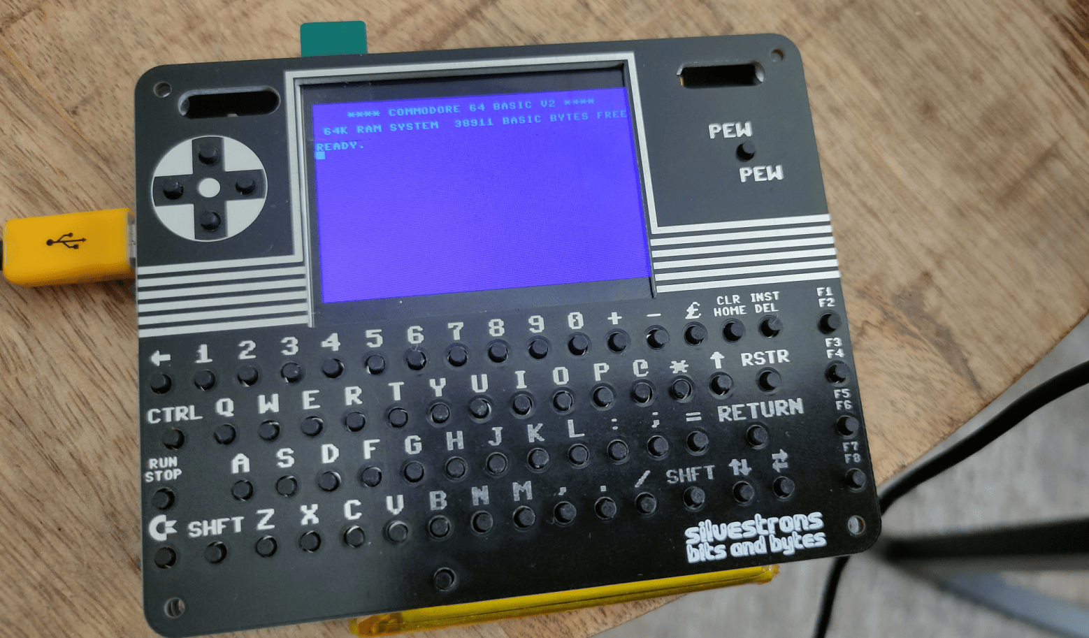
C64Pico based on MCUME see building of this in other posts.
2nd reason: While I’ve written a track loader for 8086, I never did it for C64. As a kid I didn’t have a C64, so all knowledge I have is from later years. I’ve written only a few C64 machinecode programs.
Showing first part assembly (without text Hello 2nd part)
Showing second part (no sysheader) needs to be loaded at $2000
Compile using Acme
make disk image
and run using autostart x64 (Vice emulator)
You see the first text from the 1st assemby code, then it will load the second at $2000 and does a jmp to this address. Second text will but displayed.
While i’ve been using KickAss in the past and some other 6502 compilers, I manly use acme.
Makefile I created to compile, create a C64 diskimage and run the program is as below. (No exomizer tools in this Makefile)
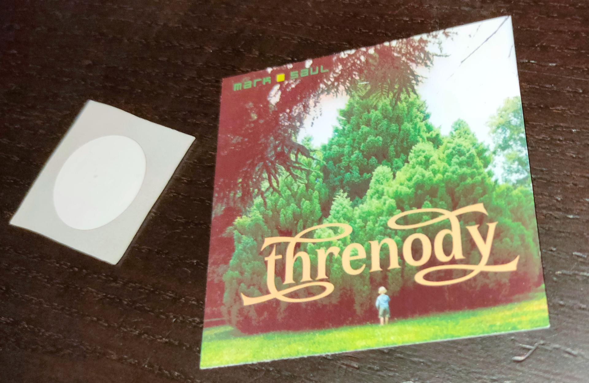
The next iteration of my Rfid controller will have a write function for the RFID tags.
Stick a tag on a cover art piece of cardboard. (see below)
Read path from data sector.
Send path to player automation
Send path to program using MQTT or website if needed.
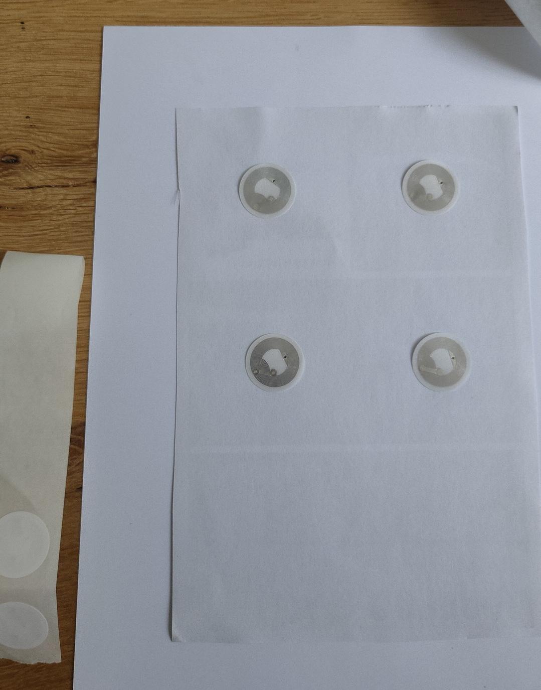
Back of printed sticker, to stick on 250gr paper below
Not sure yet, also want to implement a wifi manager on the wemos.
Changes on above idea:
Paths are too long, I could not work out how to create a working program using this.
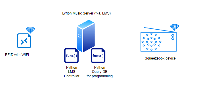
I stopped using paths, instead I’m using the Logitech media server album IDs.
Using two python scripts, I can use one for programming the card, and another script to control LMS.
How does it work
RFid device is connected to the network.
Start query.py on your LMS server. Search for an album name, it will present an ID and Album name in a list. Enter the ID you want to program, or 0 to exit. (This will also reset the programming mode)
Place an empty or previously programmed tag on the device. It will write the album ID on the tag.
Then it will start the album. Changing the tags will also just change the album playing.
(NOTE: My genre spotify player still works using this method, using the same device)
A second python script will read the Mqtt topic and control the Squeezebox player.
Python Code DB Query
import sqlite3
#paho-mqtt
import paho.mqtt.publish as publish

host = "IPMQTTBROKER"
port = 1883
topic = "spotify/rfid/in/write"
auth = {'username': 'xxxx','password': 'xxxxx'}
client_id = "spotithing"

def readSqliteTable(albumname):
    try:
        sqliteConnection = sqlite3.connect('/var/lib/squeezeboxserver/cache/library.db')
        cursor = sqliteConnection.cursor()
        albumname = "%" + albumname + "%"
        cursor.execute("select * from albums where title Like ?",
               (albumname,))
        records = cursor.fetchall()
        for row in records:
            print("Id: ", row[0],row[1])
        cursor.close()

    except sqlite3.Error as error:
        print("Failed to read data from sqlite table", error)
    finally:
        if sqliteConnection:
            sqliteConnection.close()

album = input("Album name ? ")
readSqliteTable(album)

number = input("Enter ID or 0 to quit : ")
publish.single(topic, "00000" , qos=1, hostname=host, port=port,
        auth=auth, client_id=client_id)
if number == 0:
        exit()
publish.single(topic, number, qos=1, hostname=host, port=port,
        auth=auth, client_id=client_id)
print("Program your tag")
print("Reset/disable writing using exit with 0!")
Python Code Controller (this one needs to be running at all times)
import paho.mqtt.client as mqtt
import urllib.request

def on_connect(client, userdata, flags, rc):
        print("Connected with result code {0}".format(str(rc)))
        client.subscribe("spotify/rfid/idlms")

def on_message(client, userdata, msg):
        print("Message received-> " + msg.topic + " " + str(msg.payload))  # Print a received msg
        urllib.request.urlopen("http://IPADDRESLMS:9000/anyurl?p0=playlistcontrol&p1=album_id:" + msg.payload.decode() + "&p2=cmd:load&player=b8:27:eb:11:16:ab")
#NOTE also change b8:27:eb:11:16:ab into you players MACAddress!

client = mqtt.Client("digi_mqtt_test")
client.on_connect = on_connect
client.on_message = on_message
client.connect('IPMQTTBROKER', 1883)
client.loop_forever()
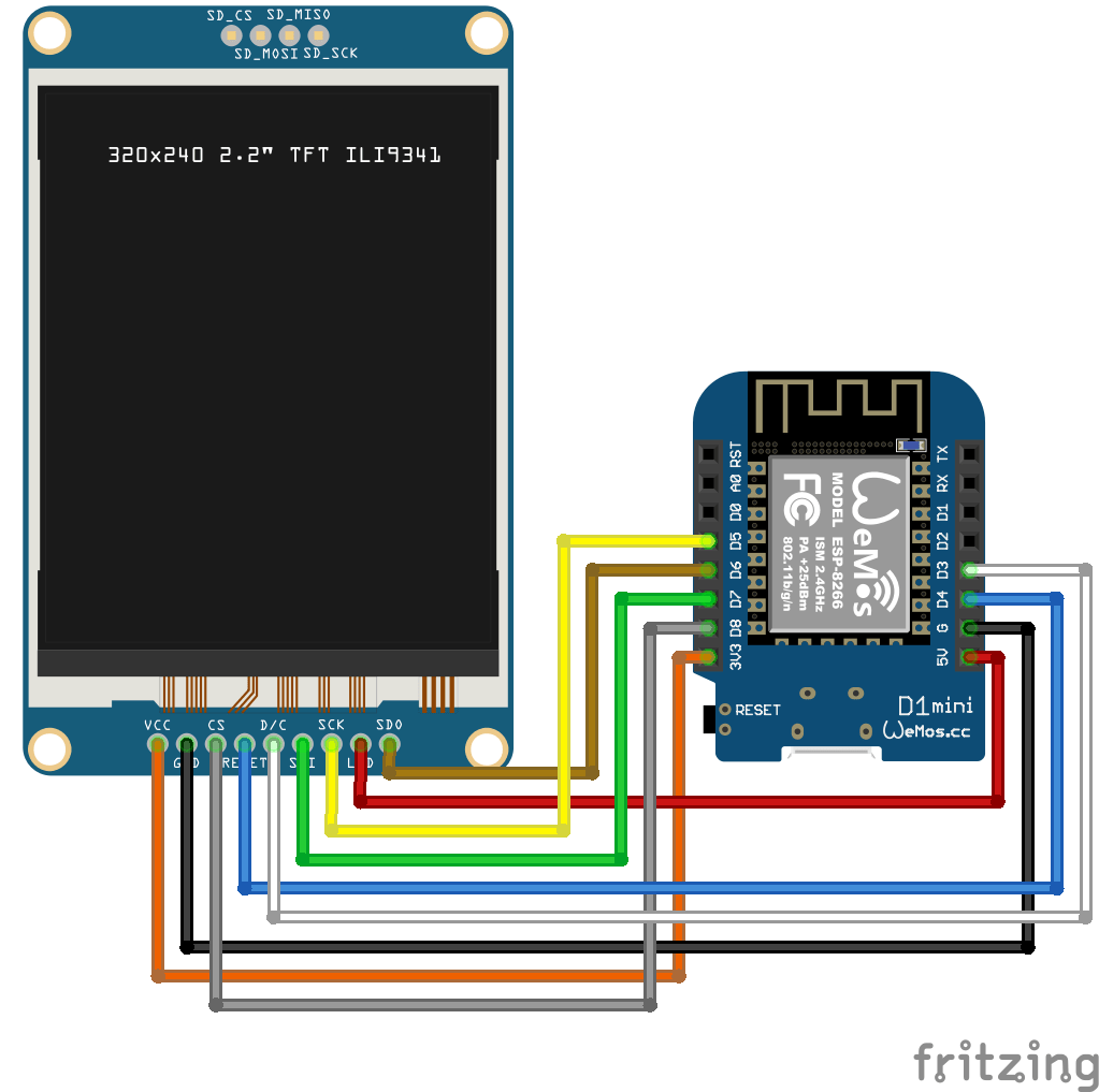
Arduino Code (see schematic in other post)
#include <Arduino.h>
#include <SPI.h>
#include <MFRC522.h>
#include <ESP8266WiFi.h>
#include <WiFiClient.h>
#include <PubSubClient.h>
#define SS_PIN 15
#define RST_PIN 0
MFRC522 mfrc522(SS_PIN, RST_PIN);
  MFRC522::StatusCode status; //variable to get card status
  byte buffer[18];  //data transfer buffer (16+2 bytes data+CRC)
  byte size = sizeof(buffer);
  uint8_t pageAddr = 0x06;  //In this example we will write/read 16 bytes (page 6,7,8 and 9).
                            //Ultraligth mem = 16 pages. 4 bytes per page.
                            //Pages 0 to 4 are for special functions.
unsigned long cardId = 0;
WiFiClient net;
PubSubClient client(net);
const char* mqtt_server = "IPMQTTBROKER";
const char* ssid = "MYSSID";
const char* password = "MYSSIDPASS";
String topicStr = "";
byte buffer2[8];

boolean Rflag=false;
int r_len;
char payload[5];
byte value[5];
void setup() {
  Serial.begin(9600);
  SPI.begin();
  mfrc522.PCD_Init();
  WiFi.mode(WIFI_AP_STA);
  WiFi.begin(ssid, password);
  client.setServer(mqtt_server, 1883);
     delay(100);
    client.setCallback(callback);
      delay(100);
    client.subscribe("spotify/rfid/in/#");
}
void reconnect() {
  while (WiFi.waitForConnectResult() != WL_CONNECTED) {
  }
  while (!client.connected()) {
    String clientId = "rfid-";
    clientId += String(random(0xffff), HEX);
    if (!client.connect(clientId.c_str(), "rfidclient", "...")) {
      Serial.print("failed, rc=");
      Serial.print(client.state());
      delay(5000);
    }
  }
  client.subscribe("spotify/rfid/in/#");
}
void callback(char* topic, byte* payload, unsigned int length) {

  Serial.print(F("Called"));
   Rflag=true; //will use in main loop
   r_len=length; //will use in main loop
   Serial.print("length message received in callback= ");
   Serial.println(length);
   int j=0;
     for (j;j<length;j++) {
       buffer2[j]=payload[j];
       }
if (r_len < 3) {
  Rflag=false;
  Serial.print(F("Set false"));
}
buffer2[j]='\0'; //terminate string
}

void loop() {
    if (!client.connected()) {
    reconnect();
  }
  client.loop();
  if (!mfrc522.PICC_IsNewCardPresent()) {
    return;
  }
  if (!mfrc522.PICC_ReadCardSerial()) {
    return;
  }
if (Rflag) {
        for (int i=0; i < 4; i++) {
    //data is writen in blocks of 4 bytes (4 bytes per page)
    status = (MFRC522::StatusCode) mfrc522.MIFARE_Ultralight_Write(pageAddr+i, &buffer2[i*4], 4);
    if (status != MFRC522::STATUS_OK) {
      Serial.print(F("MIFARE_Read() failed: (W) "));
      Serial.println(mfrc522.GetStatusCodeName(status));
      return;
    }
  }
  Serial.println(F("MIFARE_Ultralight_Write() OK "));
  Serial.println();
  Rflag=false;
}
  cardId = getCardId();
  char buffer3[10];
  sprintf(buffer3, "%lu", cardId);
  client.publish("spotify/rfid/id", buffer3);
  // Read data ***************************************************
  Serial.println(F("Reading data ... "));
  //data in 4 block is readed at once.
  status = (MFRC522::StatusCode) mfrc522.MIFARE_Read(pageAddr, buffer, &size);
  if (status != MFRC522::STATUS_OK) {
    Serial.println(F("MIFARE_Read() failed: (R)"));
    Serial.println(mfrc522.GetStatusCodeName(status));
    return;
  }

  Serial.println(F("Read data: "));
  //Dump a byte array to Serial
  for (byte i = 0; i < 5; i++) {
    Serial.write(buffer[i]);
       buffer2[i]=buffer[i];
    }
  client.publish("spotify/rfid/idlms", buffer,5);
  delay(1000);
  mfrc522.PICC_HaltA();
}

unsigned long getCardId() {
  byte readCard[4];
  for (int i = 0; i < 4; i++) {
    readCard[i] = mfrc522.uid.uidByte[i];
  }
  return (unsigned long)readCard[0] << 24
    | (unsigned long)readCard[1] << 16
    | (unsigned long)readCard[2] << 8
    | (unsigned long)readCard[3];
}
Today we worked on this project again. (Bigred and me)
There were some problems we needed to fix since last time:
It was quite hard to get the correct parts. Our display connector was only fitted with connection pins on the wrong side of the connector. (up/down) So I bought a connector with both positions populated. So we had to replace this hard to solder (40 pin) connector.
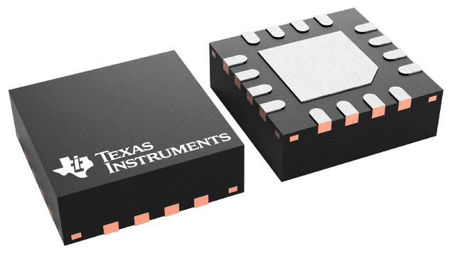
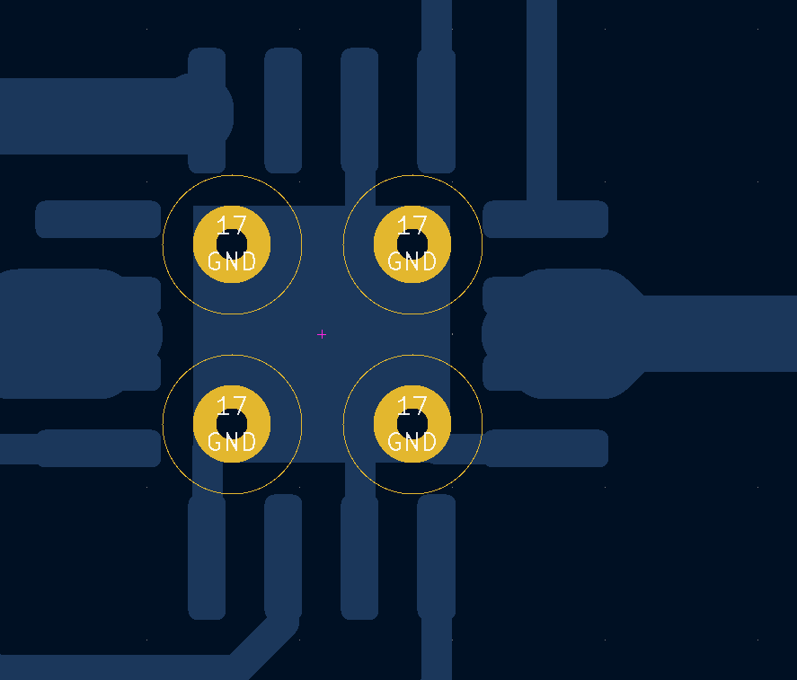
It was not clear what the orientation should be of the atmega328pb. We looked at the pinout, and followed the VCC/GND. But these are also available of the opposite side of the chip. (We missed that) Later, we saw a tiny line on the PCB, which showed the pin 1 placement. So we had to remove and replace the chip. When turning on the power, (with incorrect placement) probably fried R5 (10k resistor), on both our boards. Had to replace those also.
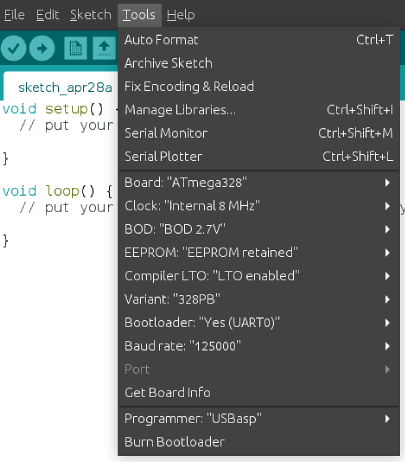
Programming the atmega328pb was not easy, see below fixes.
Compiling the pico firmware resulted in a black screen. Below the fixes I had to make to get the screen working.
Other things still to fix.
Bigreds screen.
atmega328p didn’t work for Bigred, so probably needs to replace with the pb version.
My battery controller is not charging. See bottom of page
Some of my buttons are working. The pewpew and some of the cursor keys (not as I expect, there are some up/down issues) And none of the other keys are working.
Some other things we noticed.
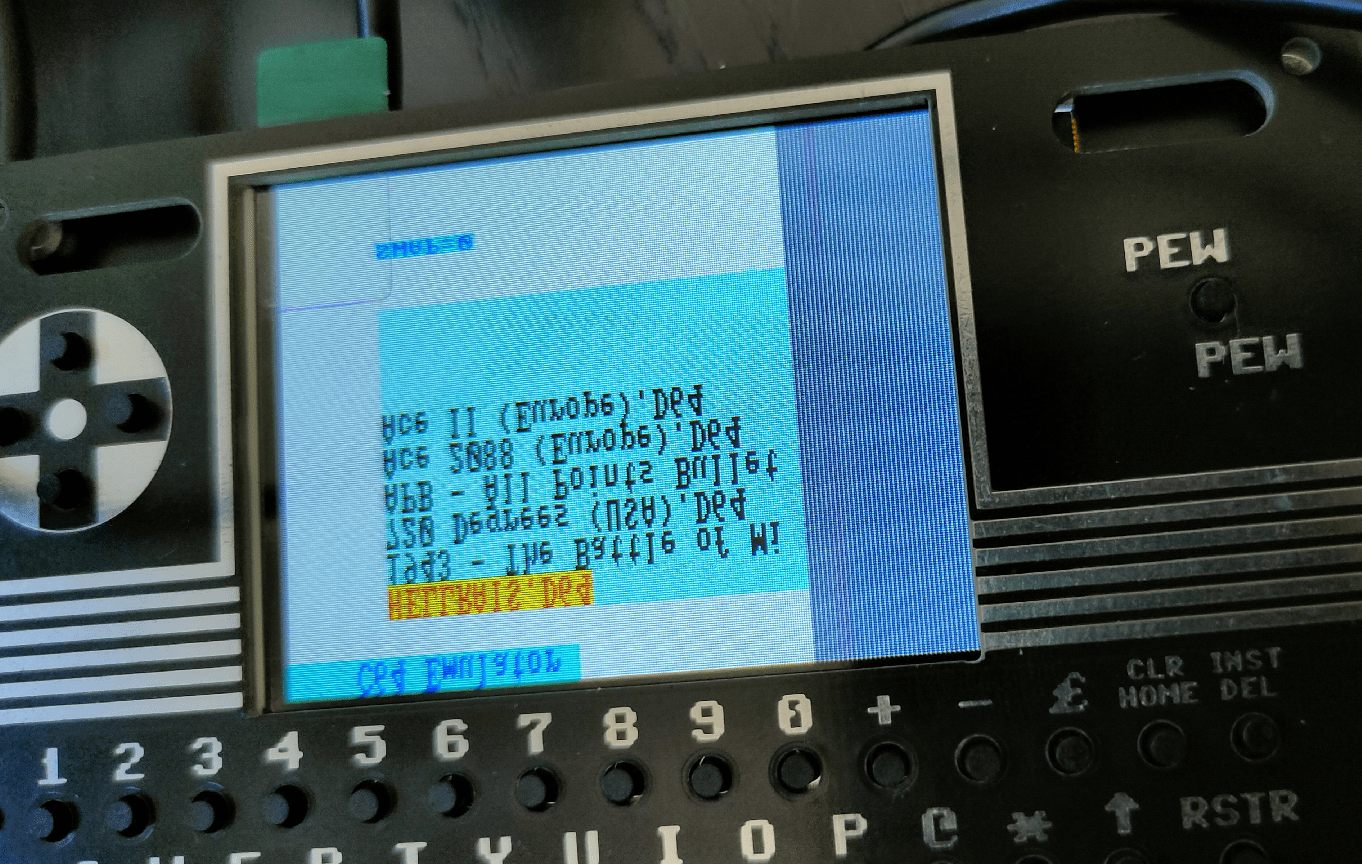
sdcard: remove partitions, format using mkfs.exfat Create a c64 directory on this filesystem where you can put the d64 files!
0402 SMD is far too small for me. There is enough room on the board to use 0805 for example. Even THT is possible, there are only a few components.
Some components are TOO close together, removing a component resulted in other small parts disconnecting also.
My friend Bigred said: If I can see it, I can solder it. But it is not easy. This probably keeps a lot of people from building it!
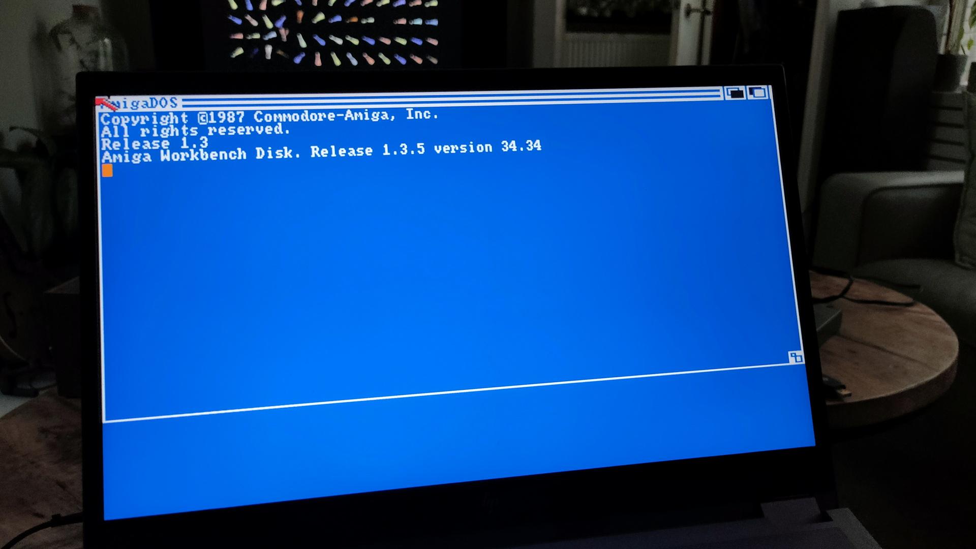
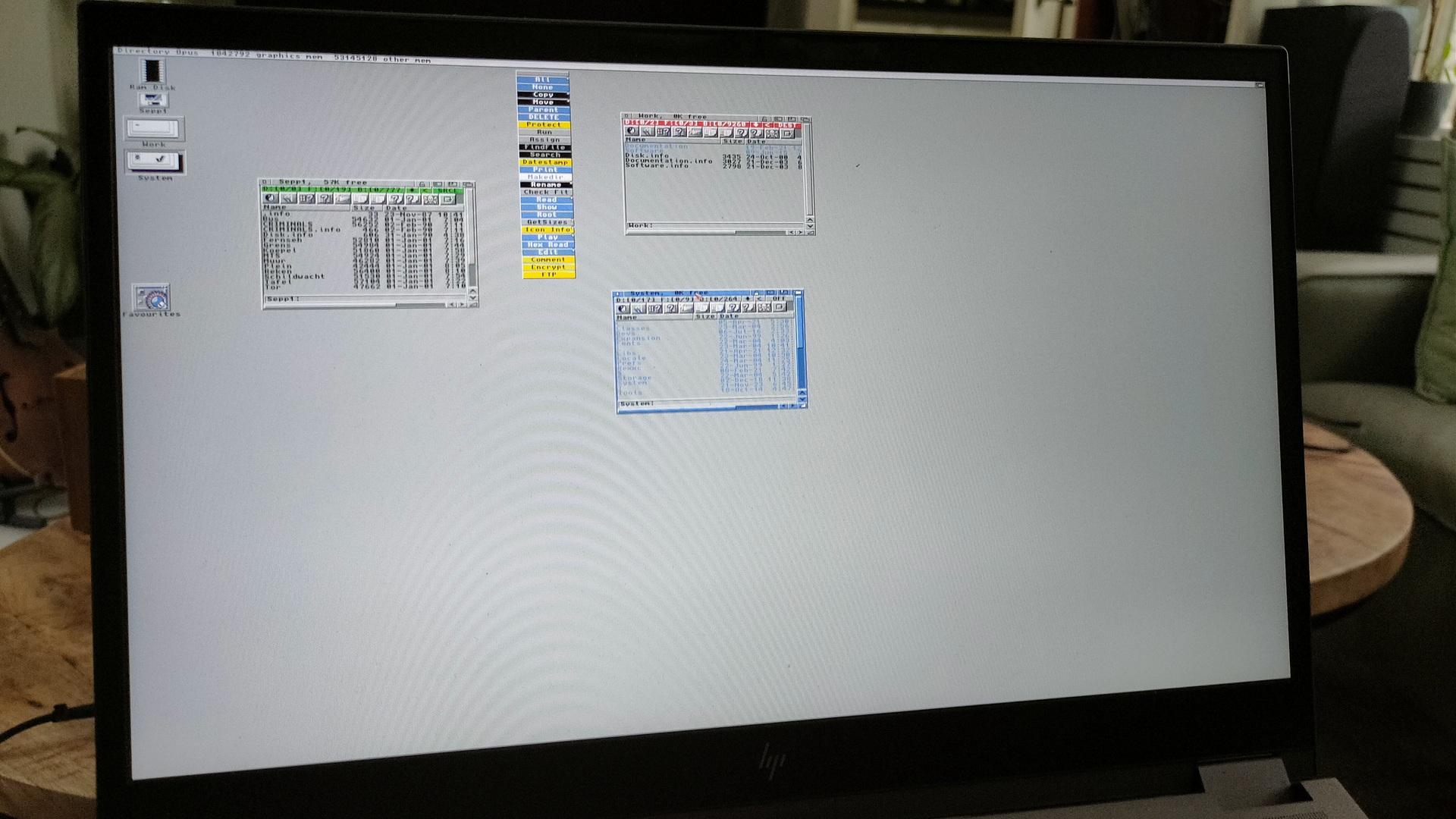
This week (while preparing for a mini retro party) I fixed some Amiga stuff.
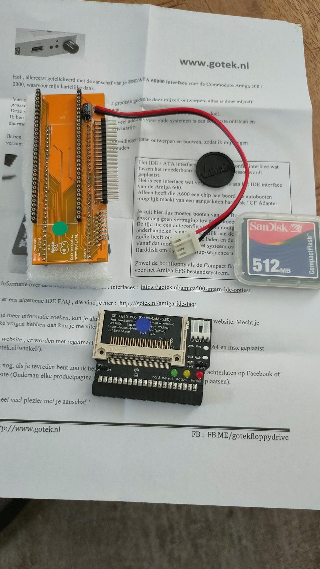
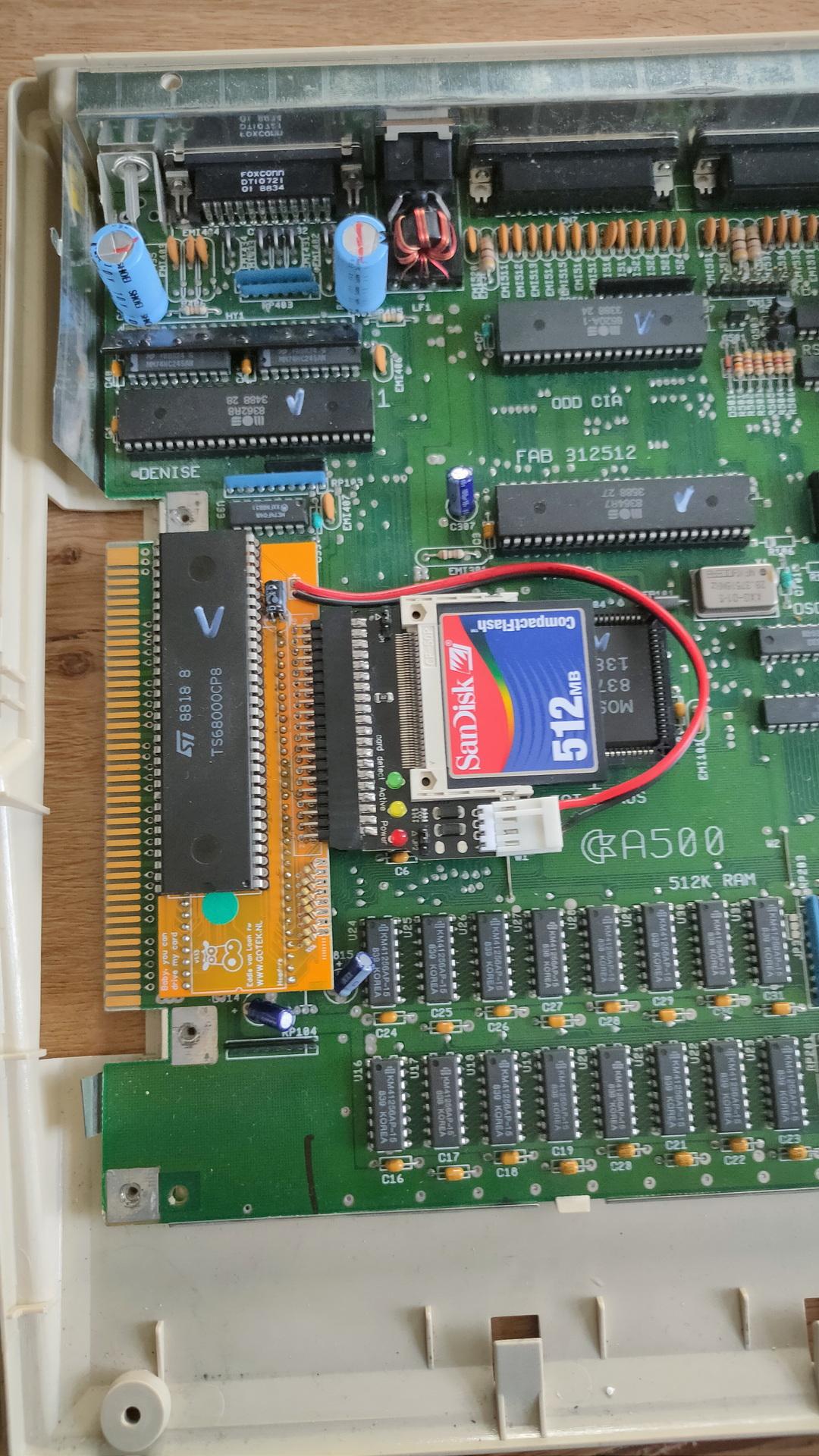
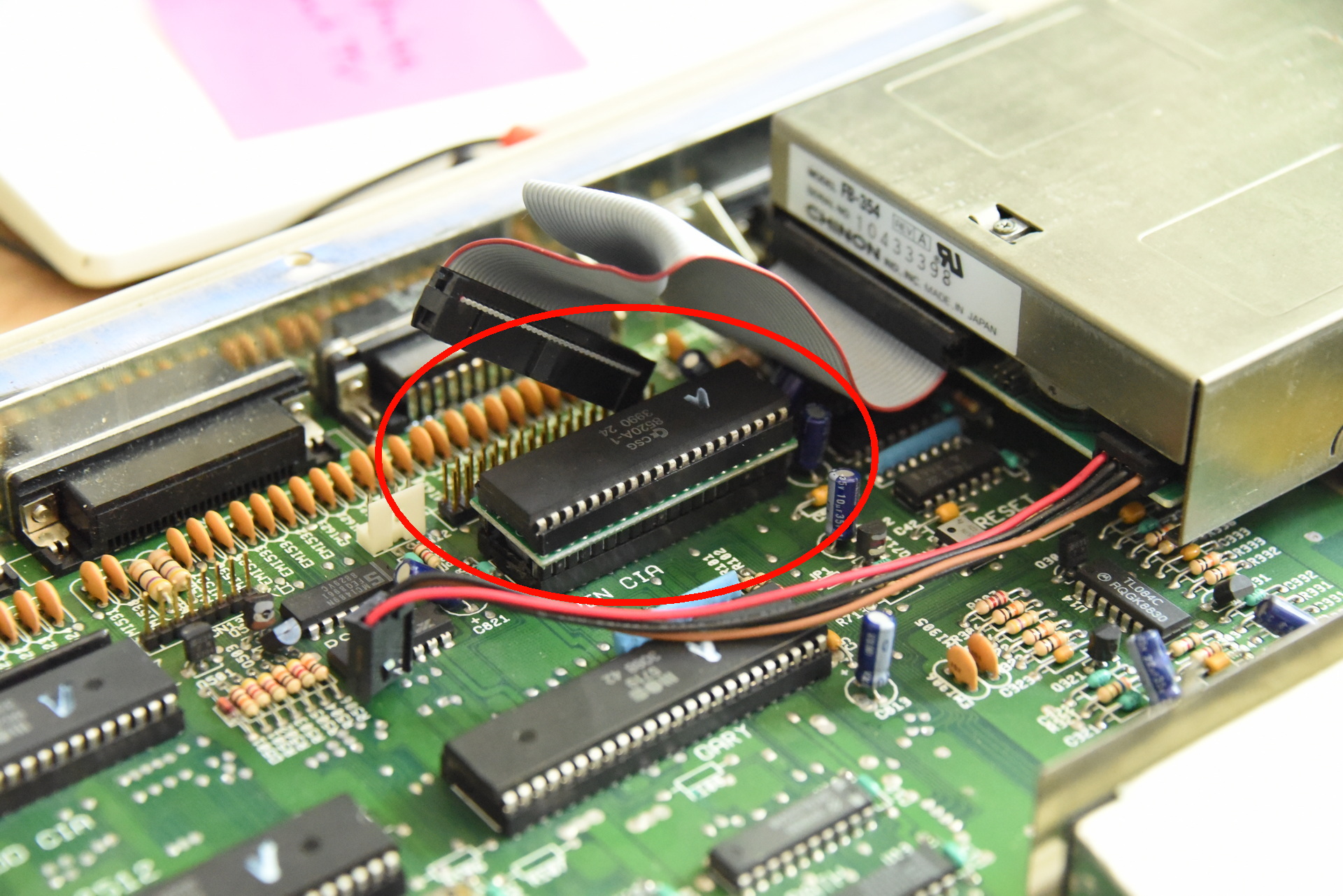
I’ve bought a new gadget.
You place this PCB between the CPU IC socket and the CPU (68000) itself.
Now running a special floppy image, which loads a driver, I can use the 512MB sdcard as “harddisk”.
It at first ran into all kinds of hangups. Checking everything, I found CIAB (8520) the culprit. Timing errors I’ve never noticed before!
Switching this one with CIAA resolved the problem. (I don’t use a printer anyway, but I have to remember that anything using the parallel port can have problems now.)
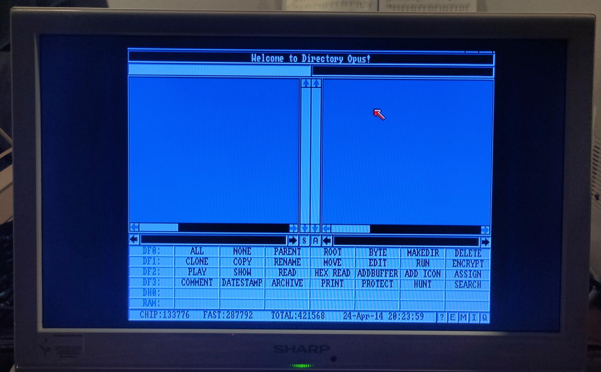
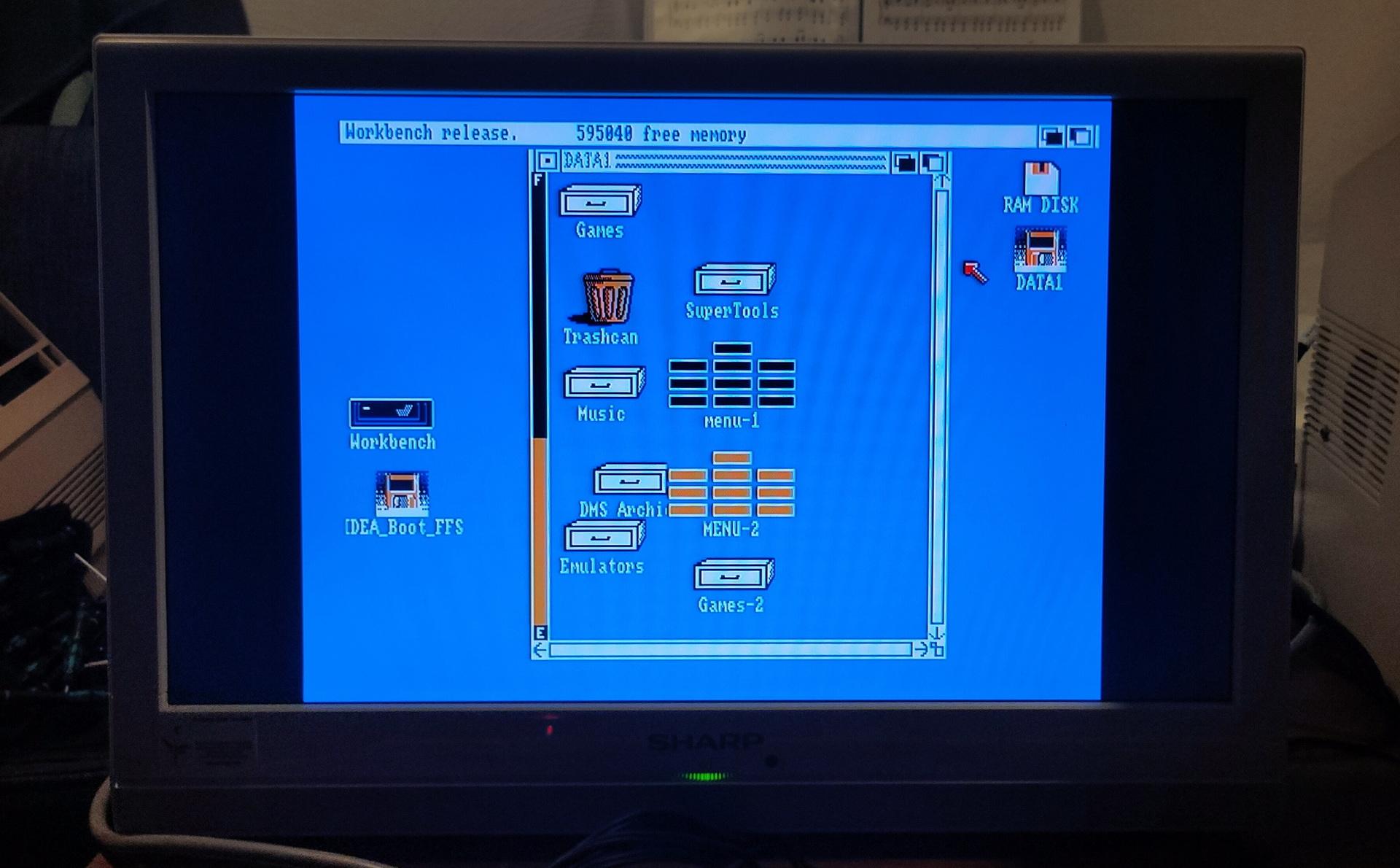
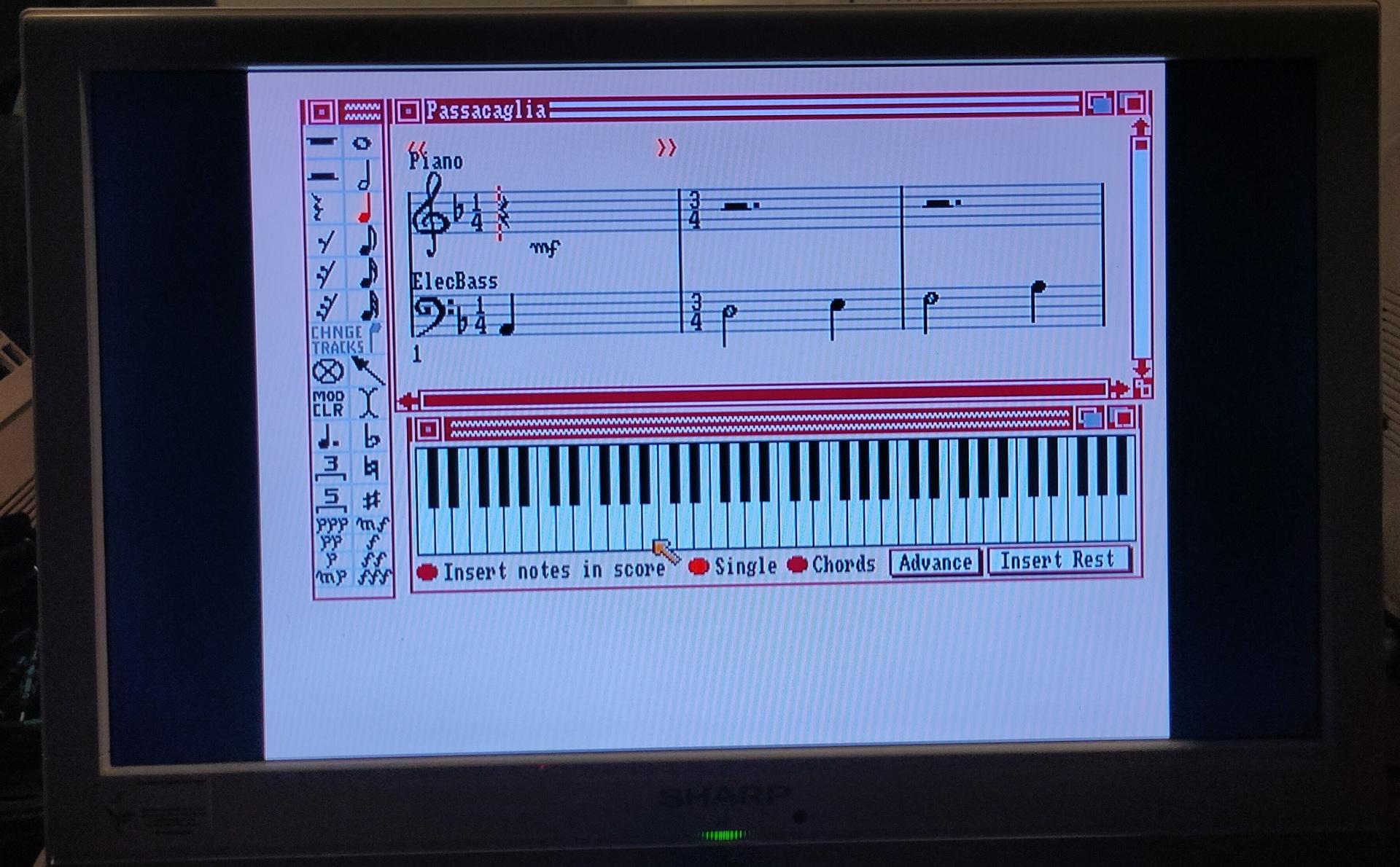
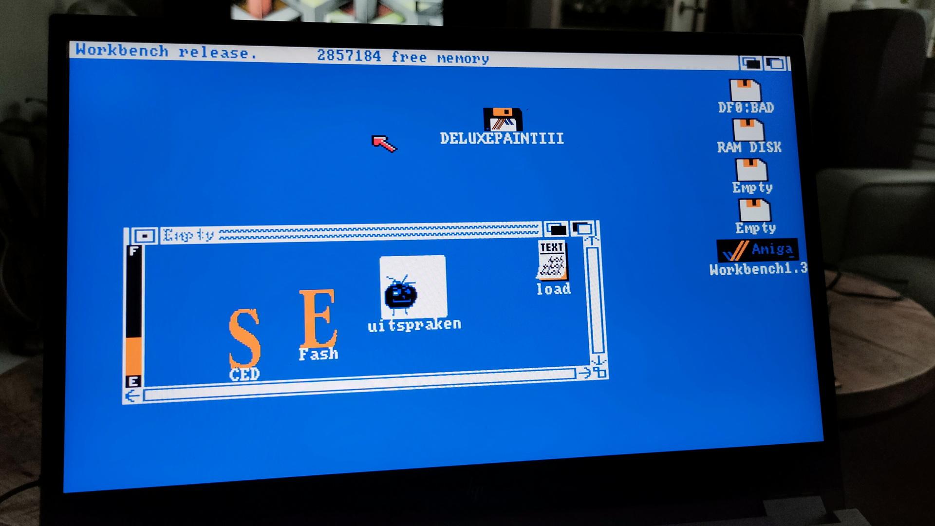
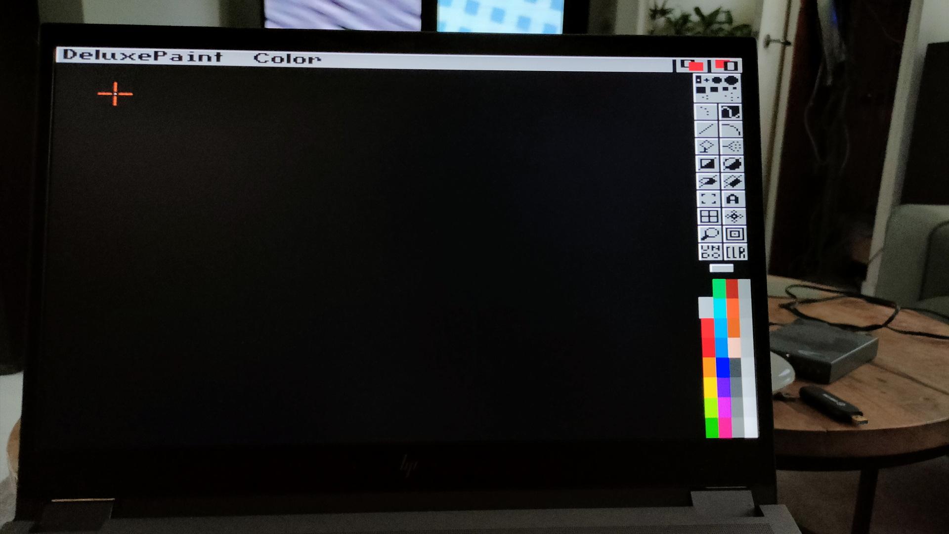
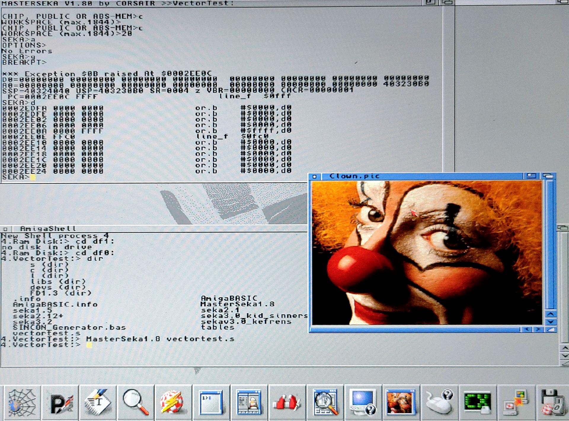
Running some programs
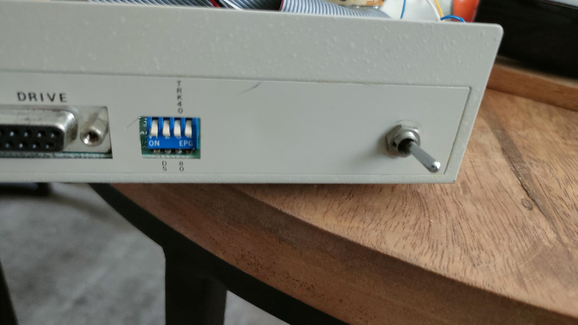
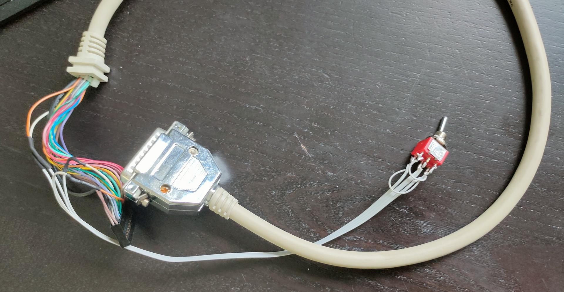
Meanwhile, I wanted to have a better control over the Amiga drives, so I’m planning to use a second switch to reassign drive numbers using a switch.
For switching Internal/External drive (df0/df1) I was using a Gotek boot switch. (Just press 3x ctrl-Amiga-Amiga)
But I have TWO external devices. The Gotek virtual disk device and a real 5.24″ drive.
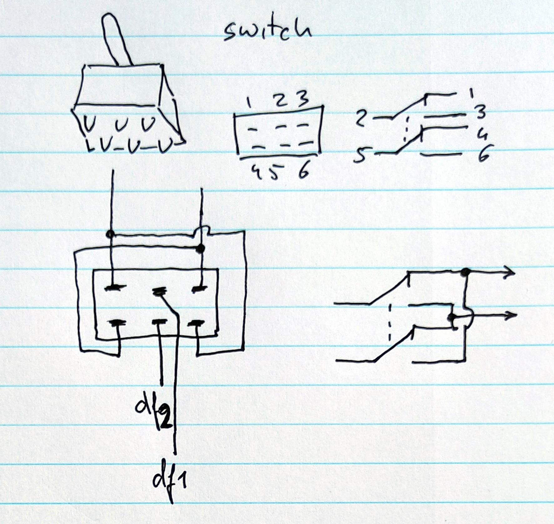
So I’m going to use a ON-ON double switch to toggle the external devices.
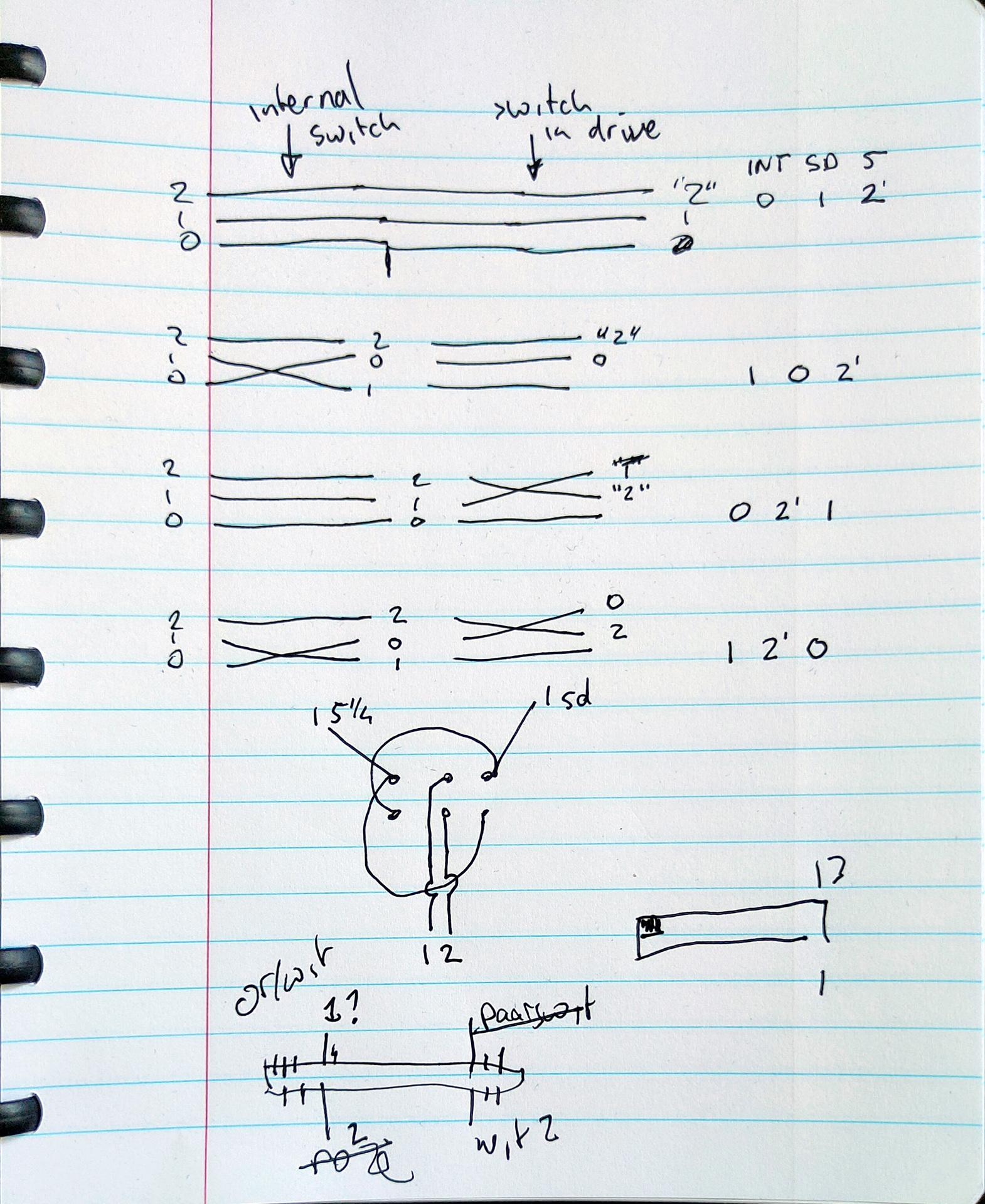
oppo_32
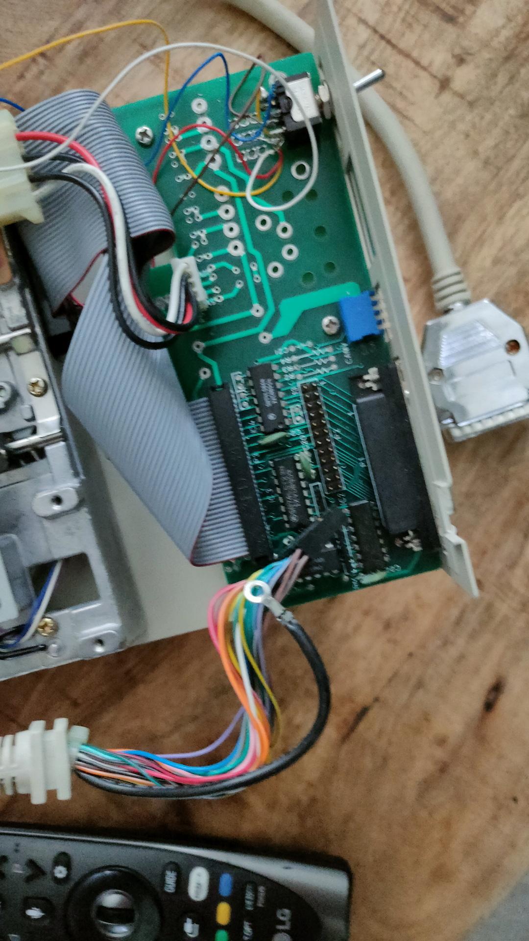
The internal switch toggles internal and external. The secondary I’m going to build into the 5.25″ drive toggles df2 and the “df1”. That way the internal drive can be 0 (boot) or 1. The external drives can be 0,1 or 2.
Bottom connector is incorrect!Better view of cross switch part
NOTE: Switch pin 21 and 9 using the cross switch!
SO: Amiga with internal drive -> External 5.24″ which has a passthrough to the Gotek.
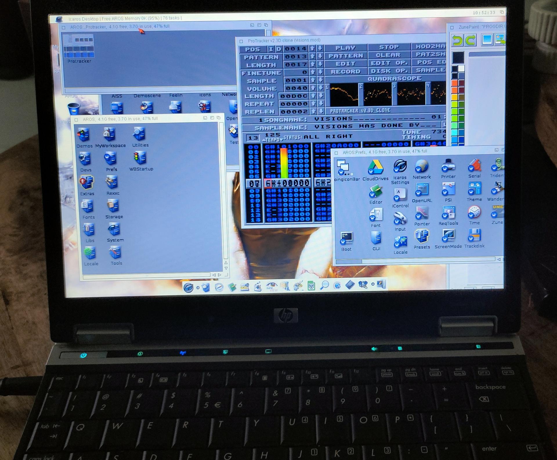
Another amiga thing fixed: I re-installed Aros (on an old Laptop this time)
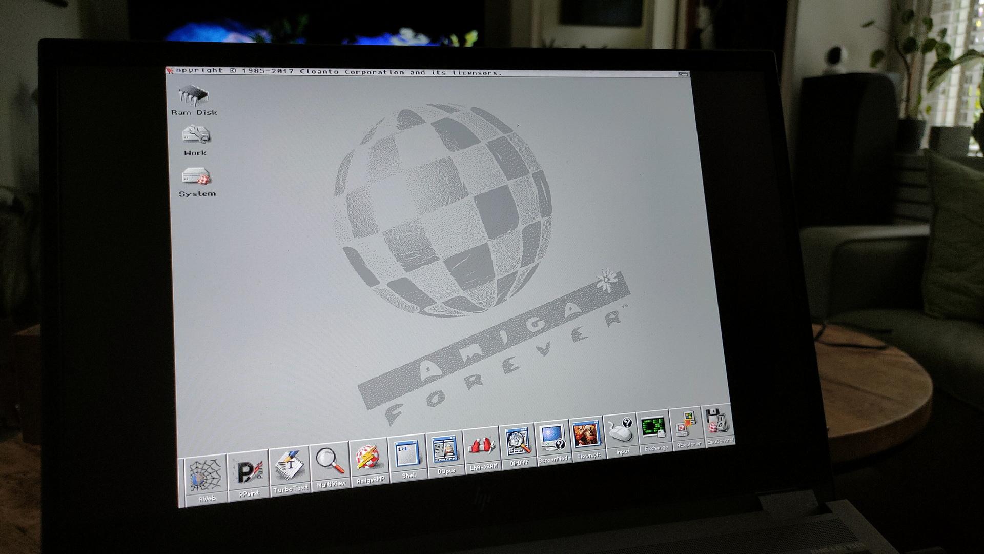
And third: I’ve bought the Amiga Forever cdrom.
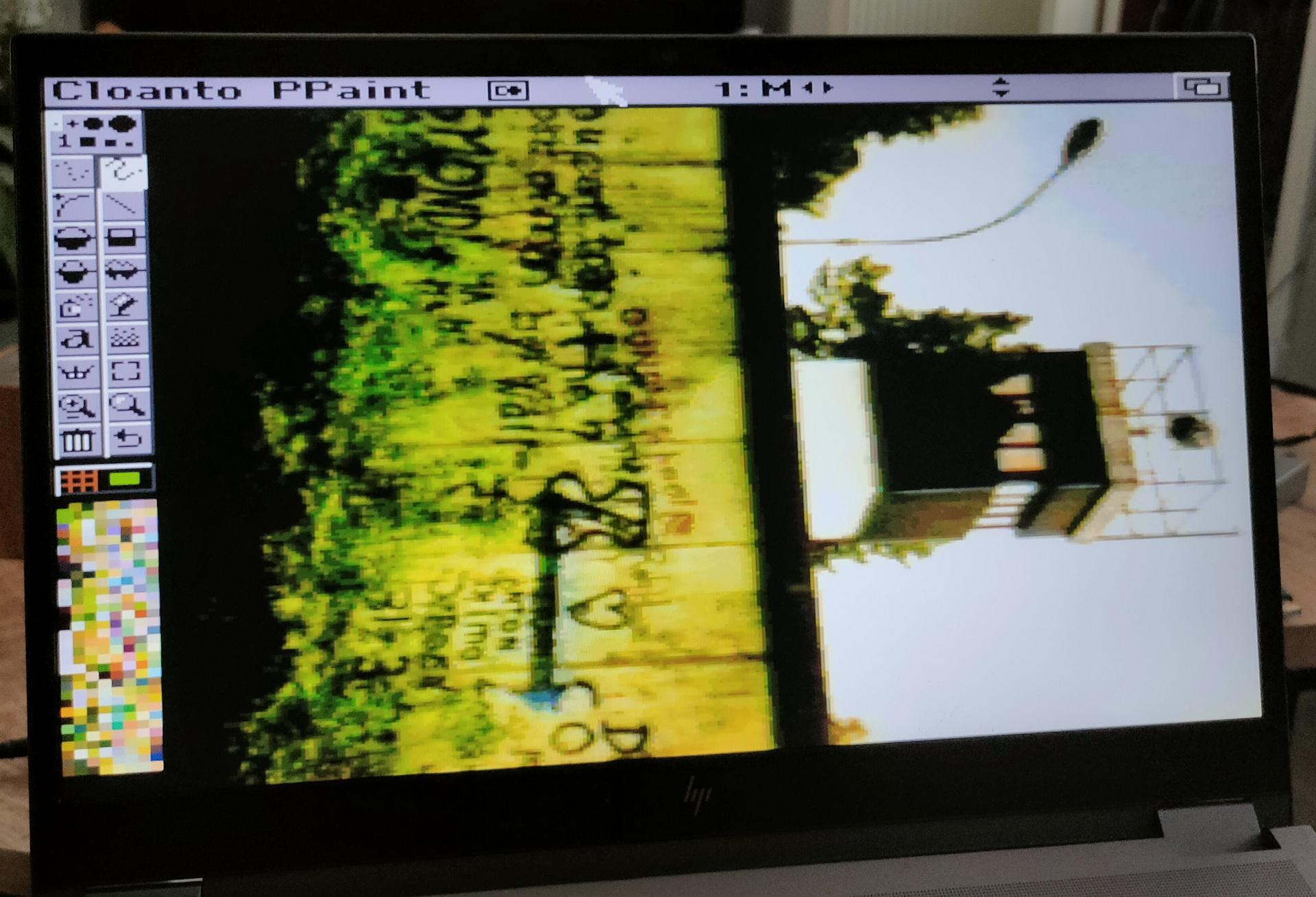
Booting kickstartDPaintWorkbench 3.xHQ PPaintEven in 1920×1080
When you get the ISO image from AmigaForever, and want to run it using Linux, do this to get it working
sudo apt install xkbfile1:i386
sudo apt install libxkbfile1:i386
mkdir -p /cdrom
sudo mount -t iso9660 ~/Downloads/AF.iso /cdrom
cd /cdrom/Private/Linux/e-uae/
./kxlight-start.sh

If you install Wine, you can use the windows gui in linux also.
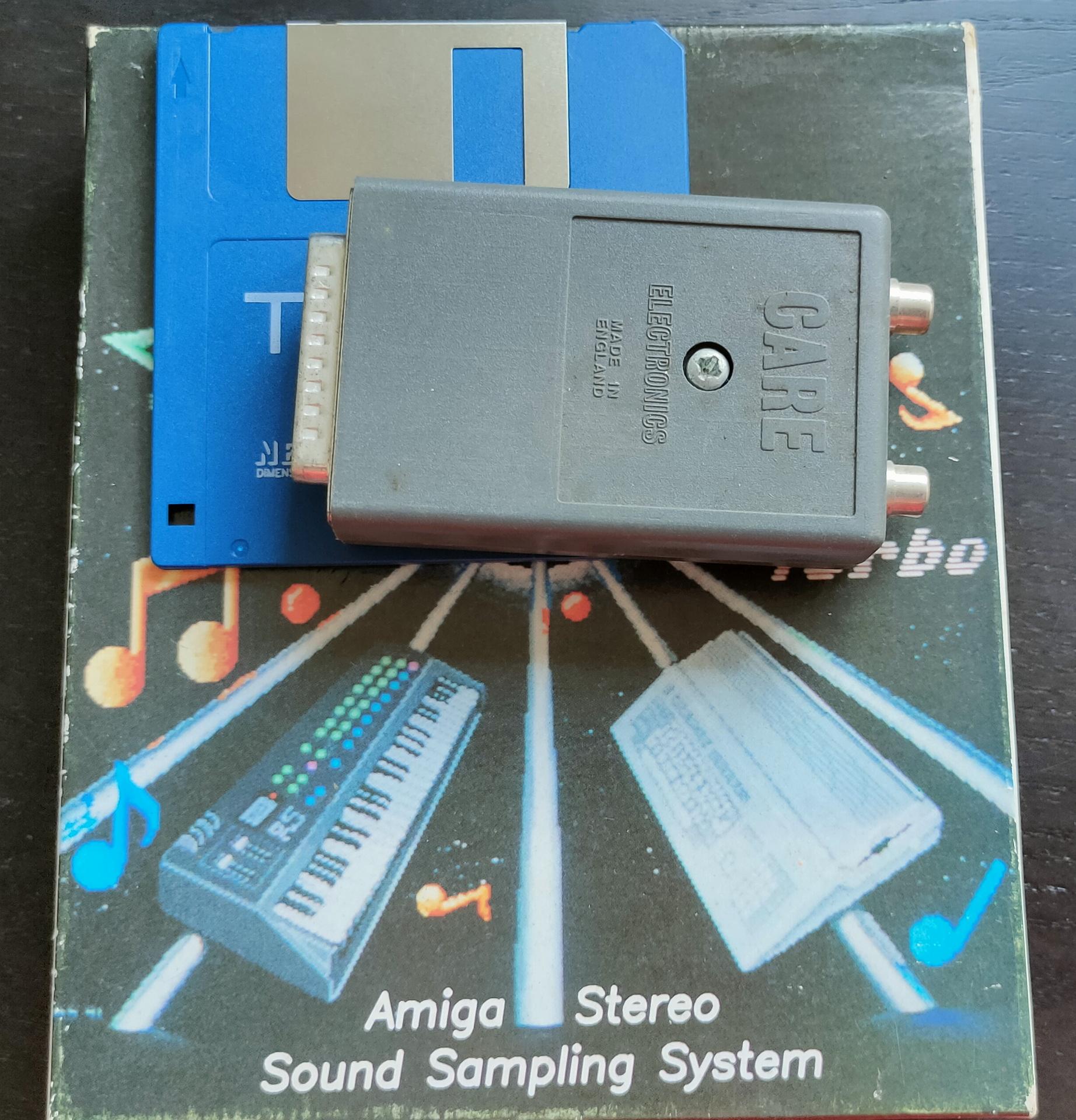
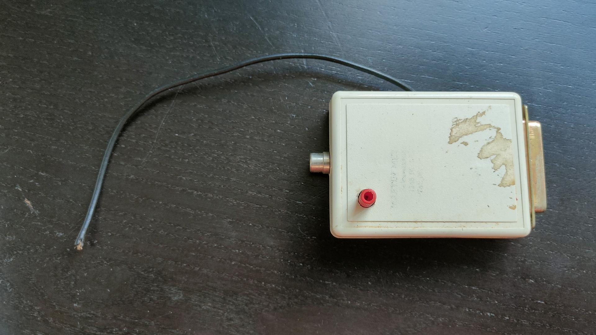
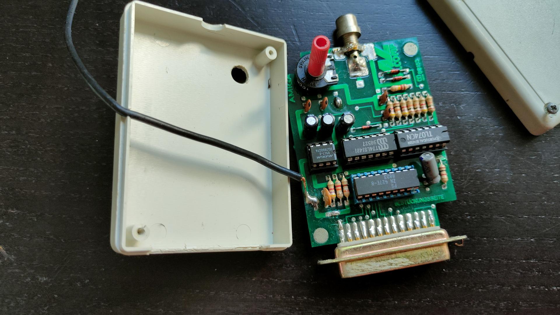
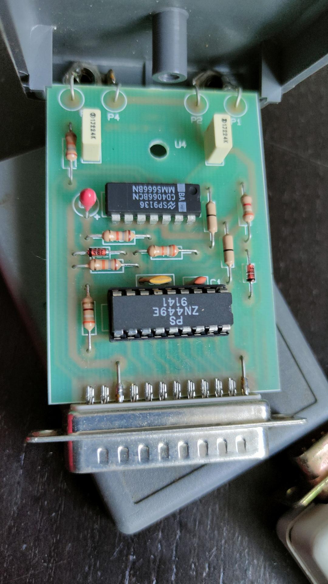
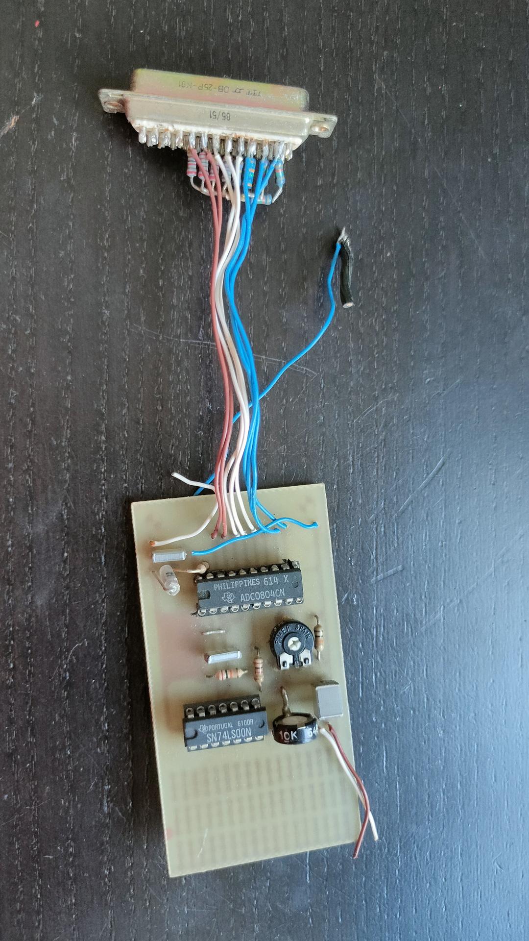
Amiga samplers
Missing a DB-9, I have to look into this.I’m not sure about this one. I made it myself. But it could be a PC version?
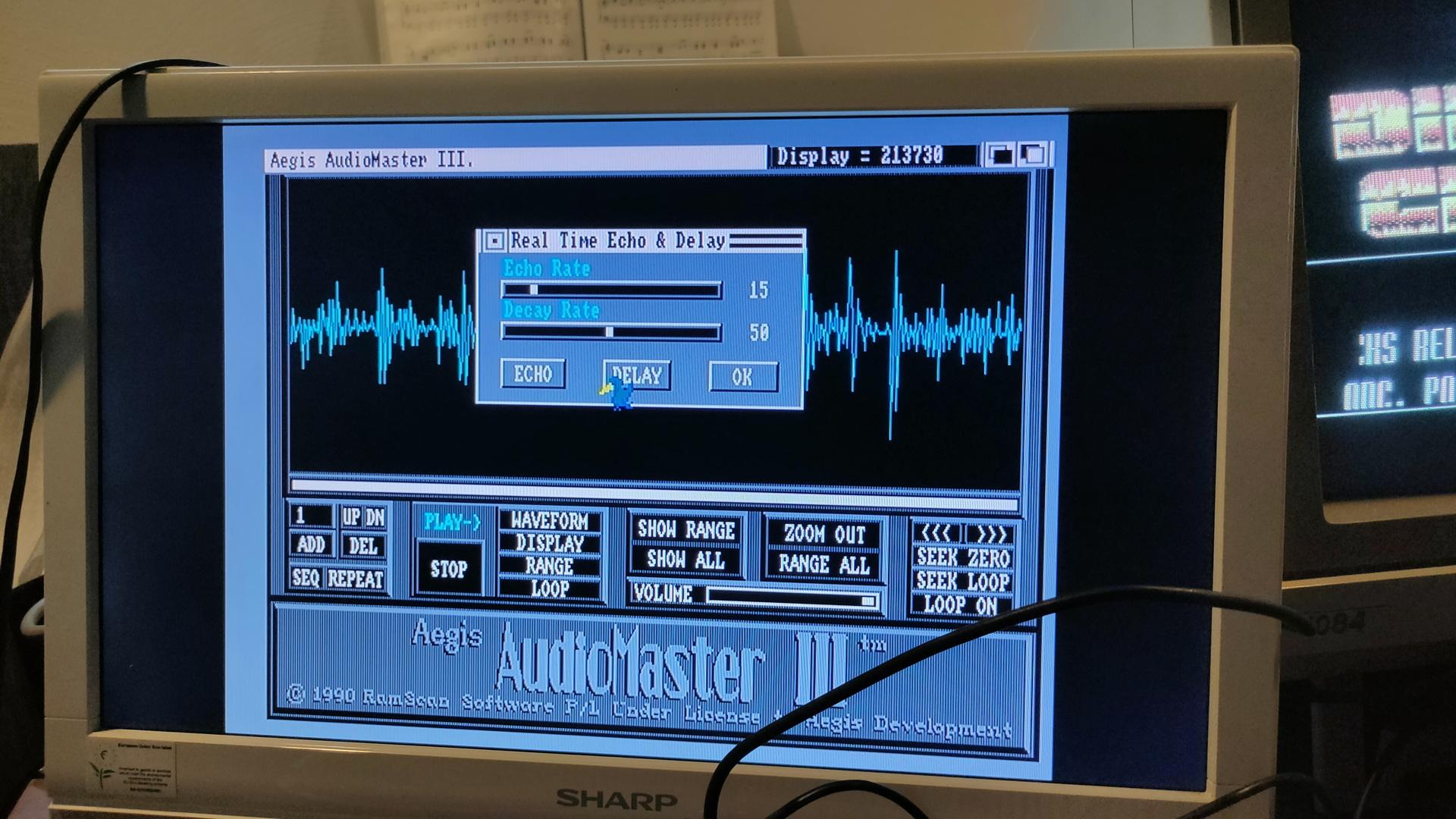
Testing the sampler (demo for Tyrone)
Sampling the sound of a C64 on an Amiga. Started (booted) the sampling program from second external drive using switch setup as above.
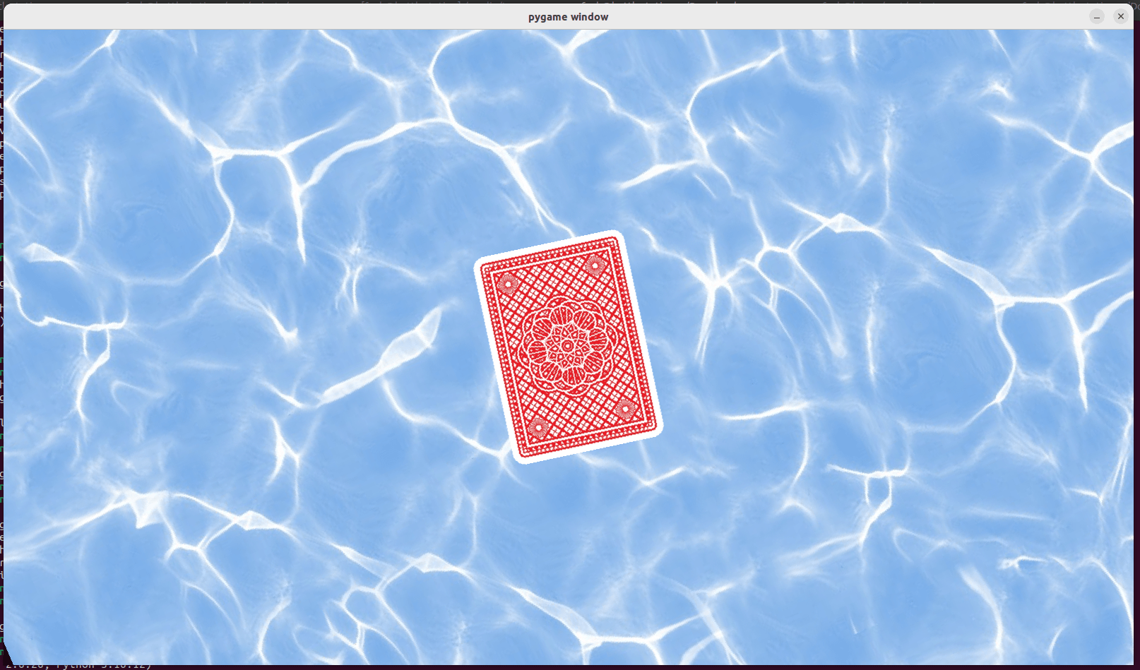
My friend Tyrone posted something he recorded from TV. It was an illusion, using rotated images.
The effect is that it seems that the card is rotating at different speeds, when pressing the s (show/unshow) key, you see the card rotating at the same speed as before.
So I wanted to try to recreate this using python. The effect is there, but a little less. What can I improve?
Mine:
Around the 30 seconds mark I disable the background, you’ll see the card rotating as before.
Original:
Better version, larger and using s key to toggle water off, to see the card rotating
<?php
// squeezebox.php
// leave playerid as is, for the default.
// change to MAC address of player to get coverart specific player
$img = file_get_contents('http://IP-LOGITECH_MEDIA_SERVER:9000/music/current/cover.jpg?player=<playerid>');
$im = imagecreatefromstring($img);
$width = imagesx($im);
$height = imagesy($im);
$newwidth = '240';
$newheight = '240';
$thumb = imagecreatetruecolor($newwidth, $newheight);
imagecopyresized($thumb, $im, 0, 0, 0, 0, $newwidth, $newheight, $width, $height);
//imagejpeg($thumb,'small.jpg'); //save image as jpg
header('Content-Type: image/jpeg');
imagejpeg($thumb);
imagedestroy($thumb);
imagedestroy($im);
?>
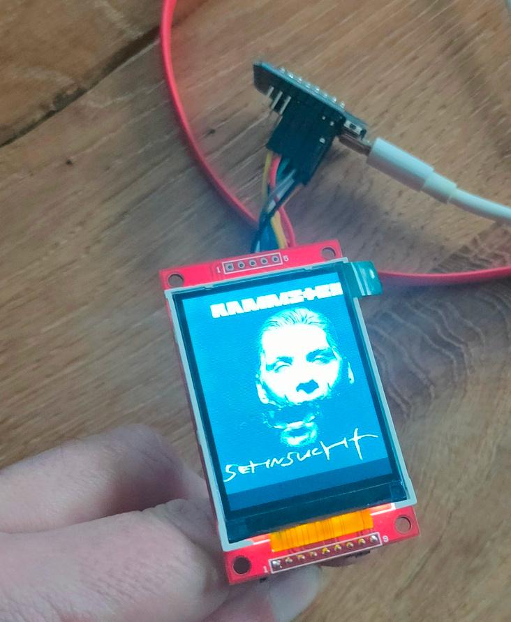
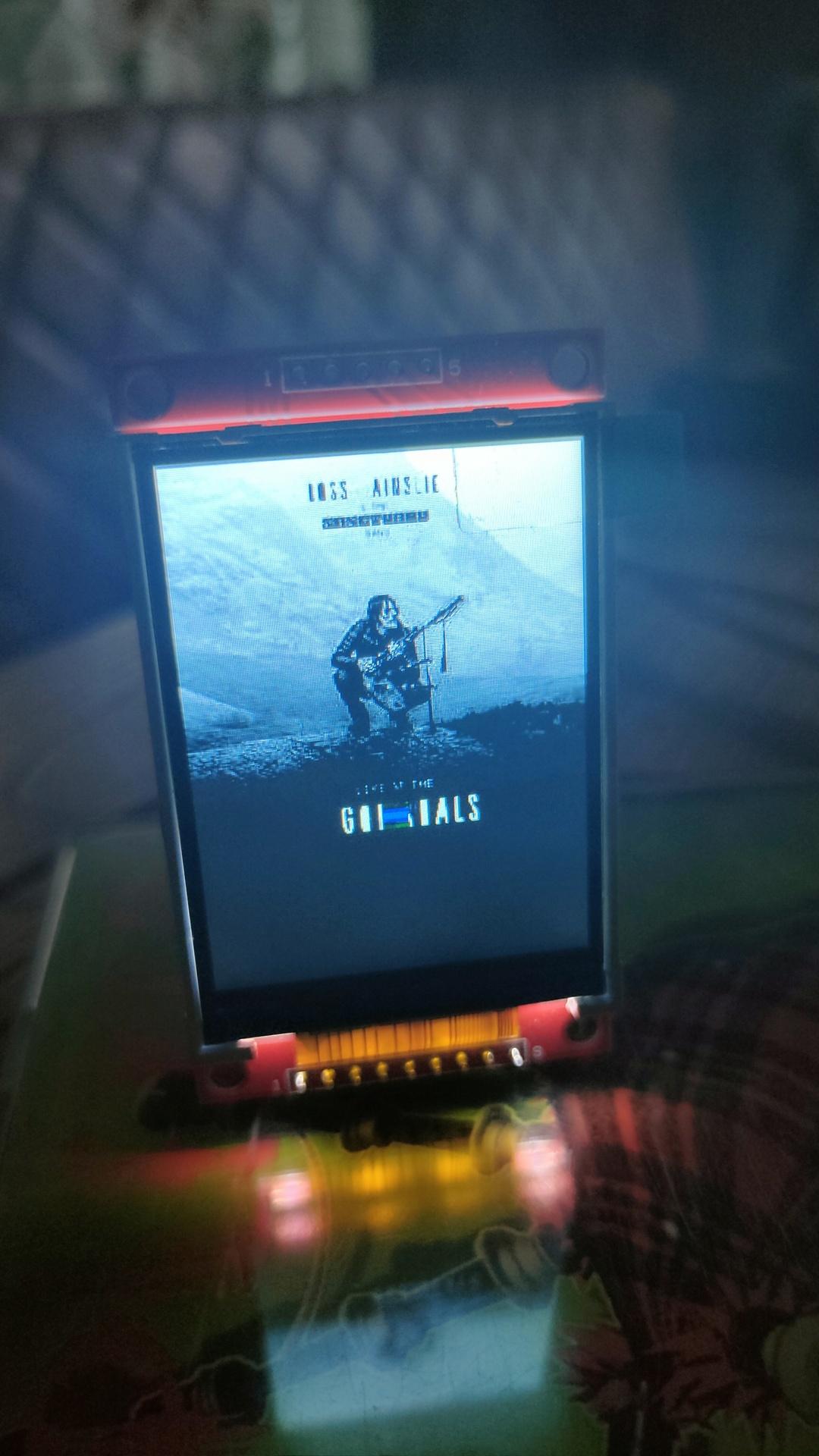
Arduino install:
Start IDE
Install TJpg_Decoder library
Open examples>Tjpeg_decoder>SPIFFS>SPIFFS_web_spiffs
change wifi credentials
and the url to your php script.
  bool loaded_ok = getFile("https://myserver/onkyo.php", "/M81.jpg"); // Note name preceded with "/"

replace bottom part with

 // while(1) yield();
 delay(5000);
     SPIFFS.remove("/M81.jpg");
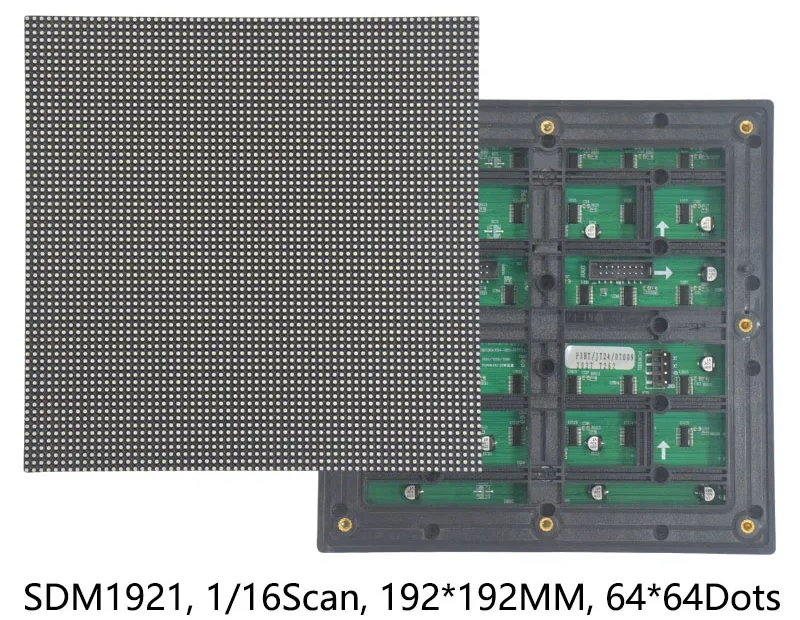
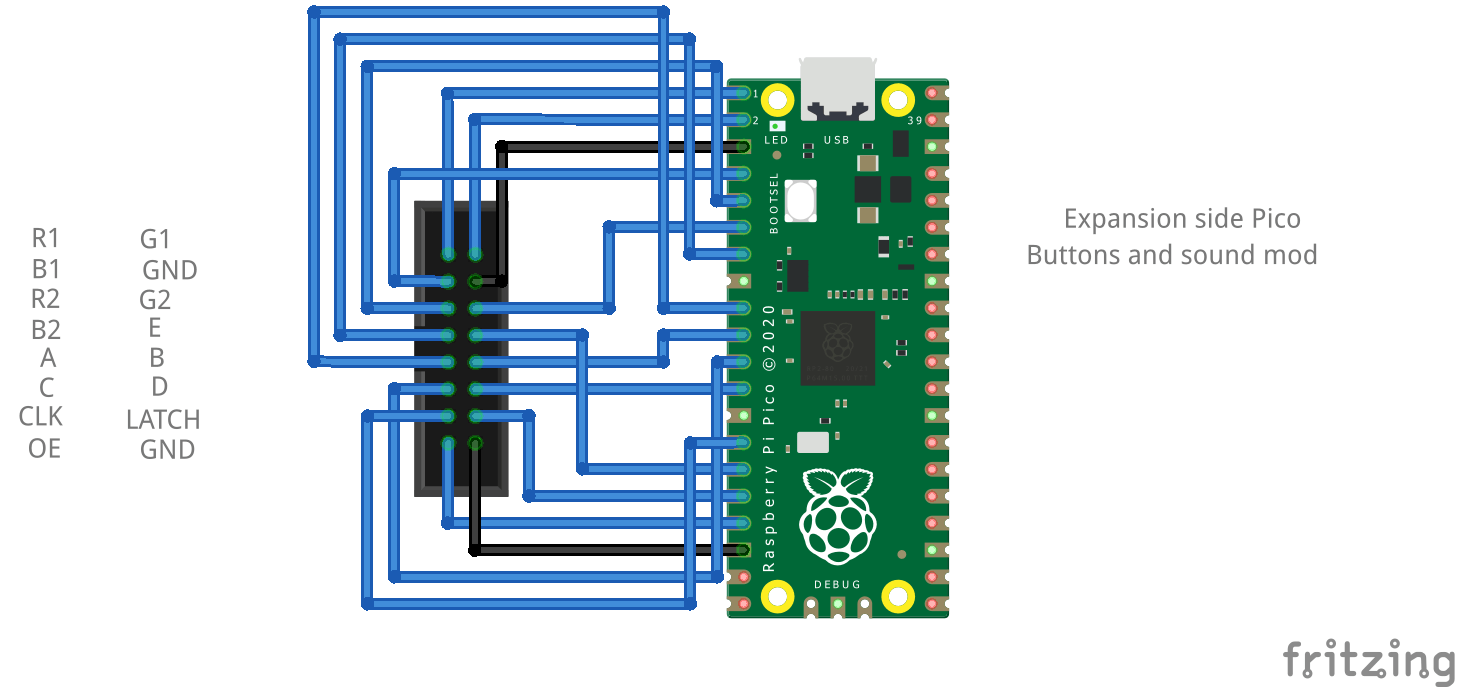
Yesterday I got this nice led matrix I mentioned before.
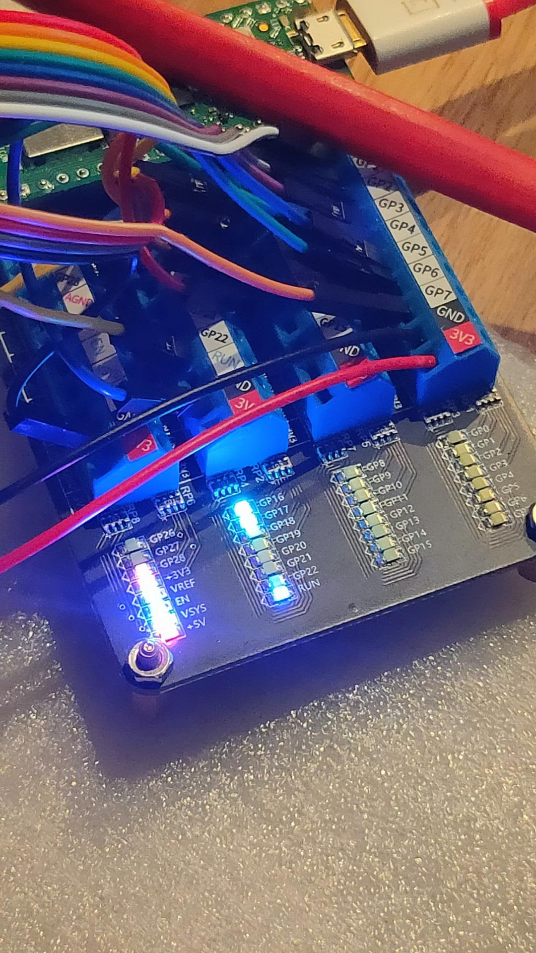
I wanted to control this display using Circuit Python and a Raspberry Pico.
Pico  Matrix
GP0   R1
GP1   G1
GP2   B1
GP3   R2
GP4   G2
GP5   B2
GP6   A
GP7   B
GP8   C
GP9   D
GP10  Clock
GP11  E
GP12  Latch
GP13  Output Enable

GND   GND ( I did both )
I installed Circuit Python and the following libraries.
adafruit_imageload, adafruit_display_text.label (the rest was already in the uf2 firmware.) (Check this link : https://circuitpython.org/board/raspberry_pi_pico/ ) I could not install the Wifi uf2 file, then I got a out of storage space when installing the adafruit libraries.
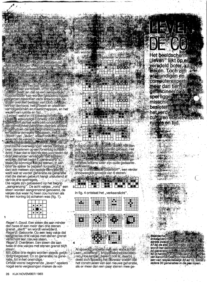
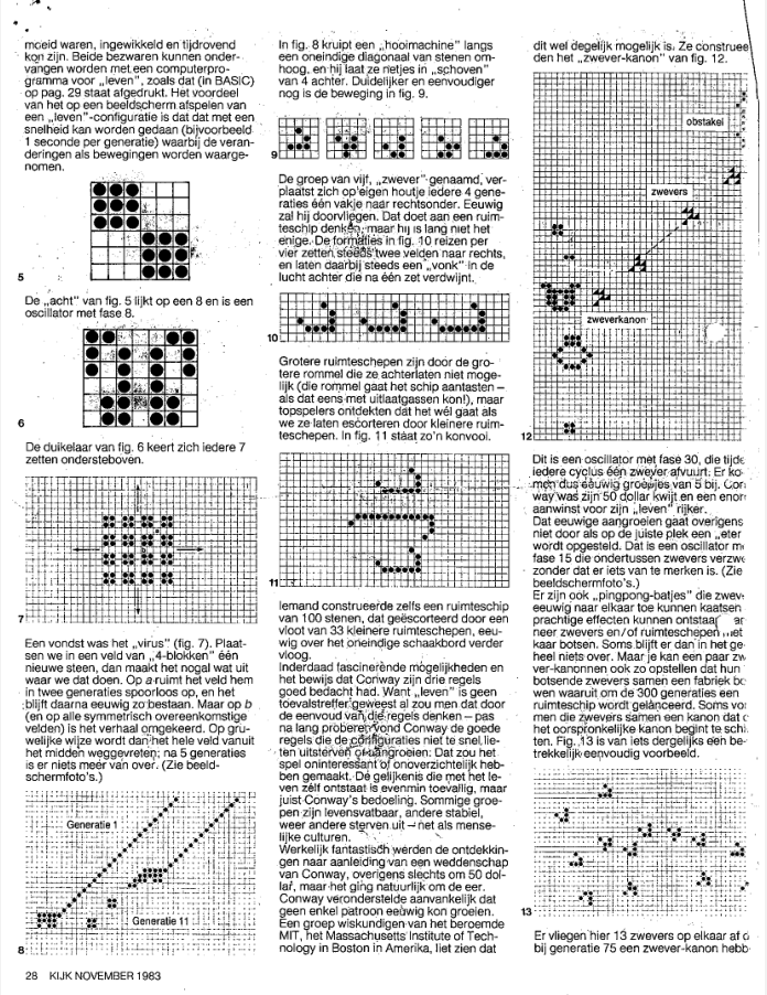
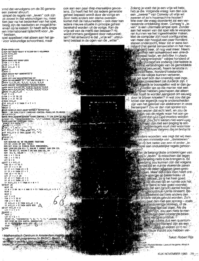
I became interested in Conway’s “Game of Life”, in 1983. Reading a article in the Dutch Magazine Kijk.
The Game of Life, also known simply as Life, is a cellular automaton devised by the British mathematician John Horton Conway in 1970. It is a zero-player game, meaning that its evolution is determined by its initial state, requiring no further input. One interacts with the Game of Life by creating an initial configuration and observing how it evolves. It is Turing complete and can simulate a universal constructor or any other Turing machine.
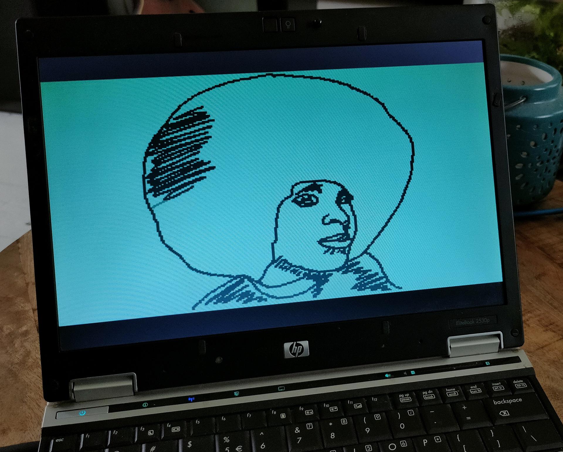
I found these on my server. Bad quality, I know. Scanned these many years ago.
The rules are:
Any live cell with fewer than two live neighbours dies, as if by underpopulation.
Any live cell with two or three live neighbours lives on to the next generation.
Any live cell with more than three live neighbours dies, as if by overpopulation.
Any dead cell with exactly three live neighbours becomes a live cell, as if by reproduction.
When playing with the Basic code as a kid, I wanted to try if it was possible to make a 3D version of this.
I came up with the following rules:
Birth : 4 alive neighbours needed
Survive : 5 or 6 neighbours
Dead : below 4 and over 6
I think there should be a BBC Acorn basic version I wrote somewhere.
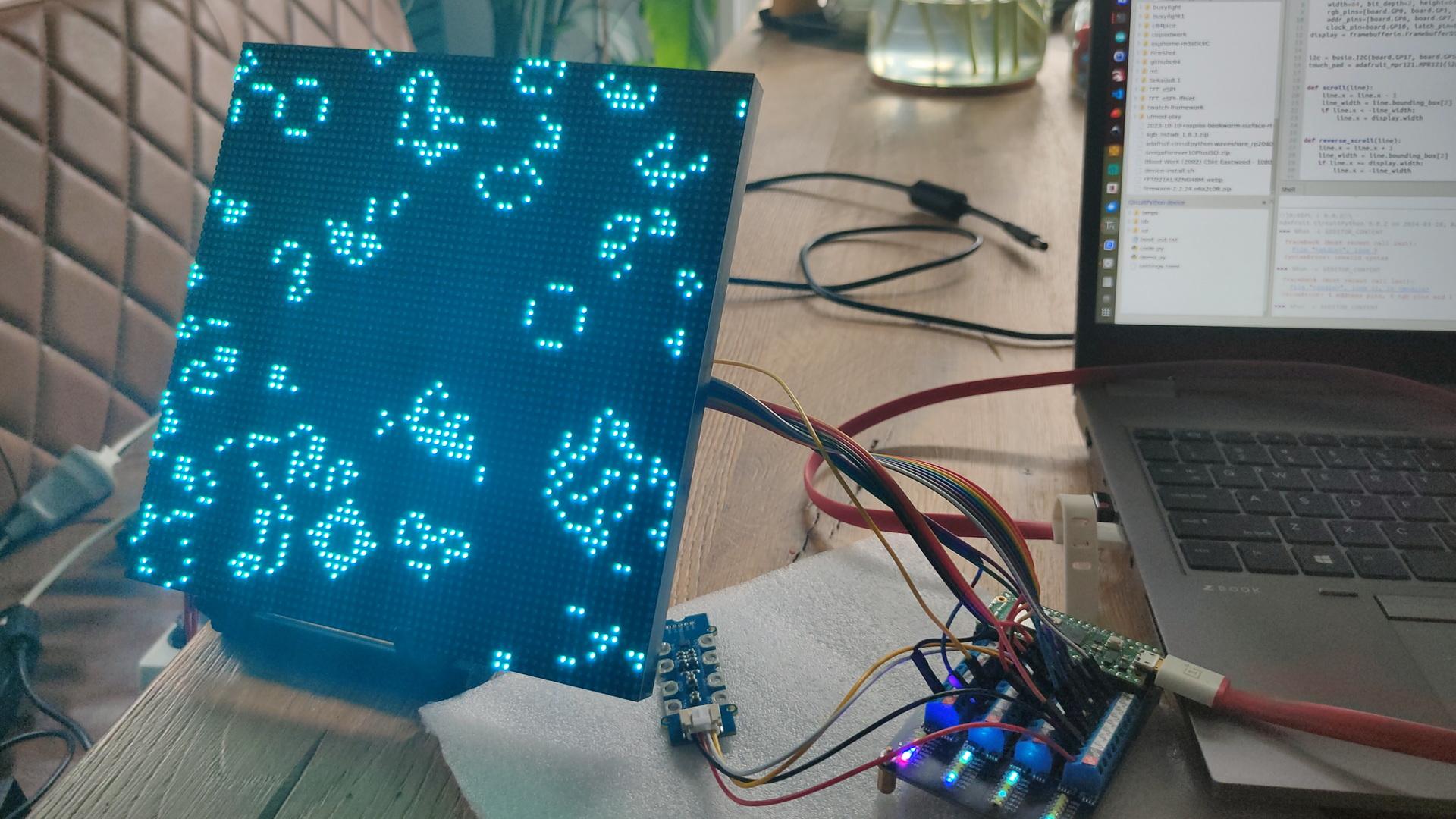
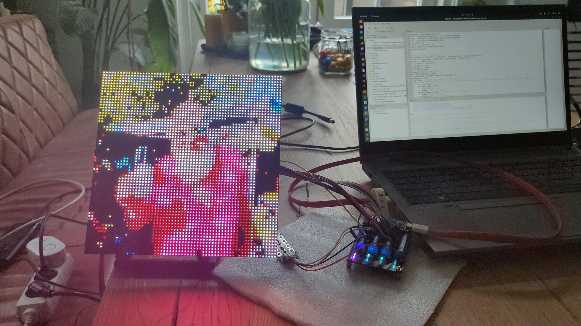
Back to the display
Pico BoardGame of LifeDisplaying a imageGreetings to my friendsGame of Life starting with my Logo plus a gliderA single Gosper‘s glider gun creating gliders
Code for the glider gun
    conway_data = [
        b'                        +           ',
        b'                      + +           ',
        b'            ++      ++            ++',
        b'           +   +    ++            ++',
        b'++        +     +   ++              ',
        b'++        +   + ++    + +           ',
        b'          +     +       +           ',
        b'           +   +                    ',
        b'            ++                      ',
    ]