Searx is a free and open-source metasearch engine, available under the GNU Affero General Public License version 3, with the aim of protecting the privacy of its users. To this end, Searx does not share users’ IP addresses or search history with the search engines from which it gathers results.
It’s easy to install using docker, but i wanted to add my own mysql server data. ( pipetune search engine data in below example )
There are many search plugins and quite hackable.
But there was a missing python module in a docker image.
ModuleNotFoundError: No module named ‘mysql’
So i build a new docker image based on the original
# Install docker and docker-compose

cd /usr/local
git clone https://github.com/searxng/searxng-docker.git
cd searxng-docker
Edit the .env file to set the hostname
Generate the secret key sed -i "s|ultrasecretkey|$(openssl rand -hex 32)|g" searxng/settings.yml
Edit the searxng/settings.yml file according to your need
Check everything is working: docker-compose up
Run SearXNG in the background: docker-compose up -d
I’ve changed the docker-compose.yaml
Changed
<     image: searxng/searxng:latest

into
>     build: .

And
changed the listen address
<      - "127.0.0.1:8080:8080"
into
>      - "8080:8080"
Created a Dockerfile
FROM searxng/searxng:latest
RUN pip install mysql-connector-python
Changed searxng/settings.yml
engines:
  - name: tunesdb
    engine: mysql_server
    host: 10.12.0.xx
    database: pipetunesearch
    username: xxxxxxx
    password: xxxxxxx
    limit: 50
    query_str: 'SELECT * from tunes WHERE tunename=%(query)s'
I could not use a like statement in de sql query .. have to look into that
query_str: 'SELECT * from tunes WHERE tunename like %(query)%' .. doesn´t work
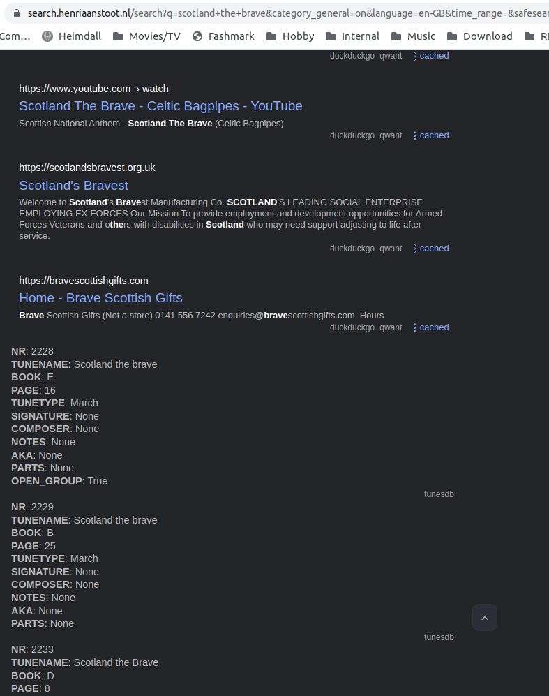
Example showing own data
To complete this post the reverse proxy info ..
<VirtualHost *:443>
   SSLEngine on
   SSLProxyEngine On

   SSLProtocol all -SSLv2 -SSLv3 +TLSv1
   SSLCipherSuite ALL:!ADH:!EXPORT:!SSLv2:!RC4+RSA:+HIGH:+MEDIUM

   SSLCertificateFile wildcard.cer
   SSLCertificateKeyFile my.key
   SSLCertificateChainFile GlobalSignRootCA.cer
   SSLCertificateChainFile AlphaSSLCA-SHA256-G2.cer

   CustomLog /var/log/httpd/search_ssl_request_log "%t %h %{SSL_PROTOCOL}x %{SSL_CIPHER}x \"%r\" %b"

    ServerAdmin webmaster@henriaanstoot.nl
    ServerName search.henriaanstoot.nl

ProxyRequests Off
ProxyPreserveHost On
SSLProxyVerify none
SSLProxyCheckPeerCN off
SSLProxyCheckPeerName off

<Location />
ProxyPass  http://dockerhostip:8080/
ProxyPassReverse  http://dockerhostip:8080/
</Location>

    ErrorLog /var/log/httpd/search.henriaanstoot.nl-error.log
    CustomLog /var/log/httpd/search.henriaanstoot.nl-access.log combined
</VirtualHost>