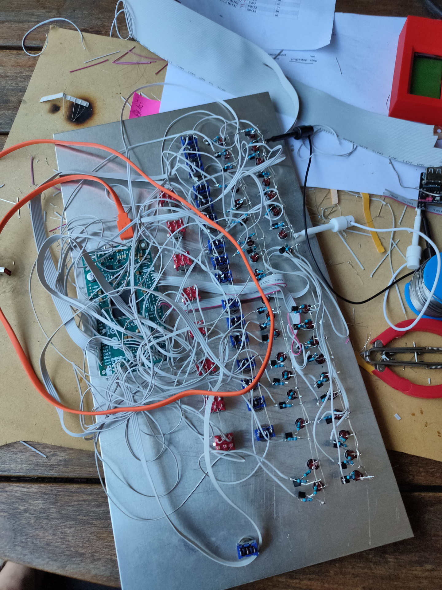
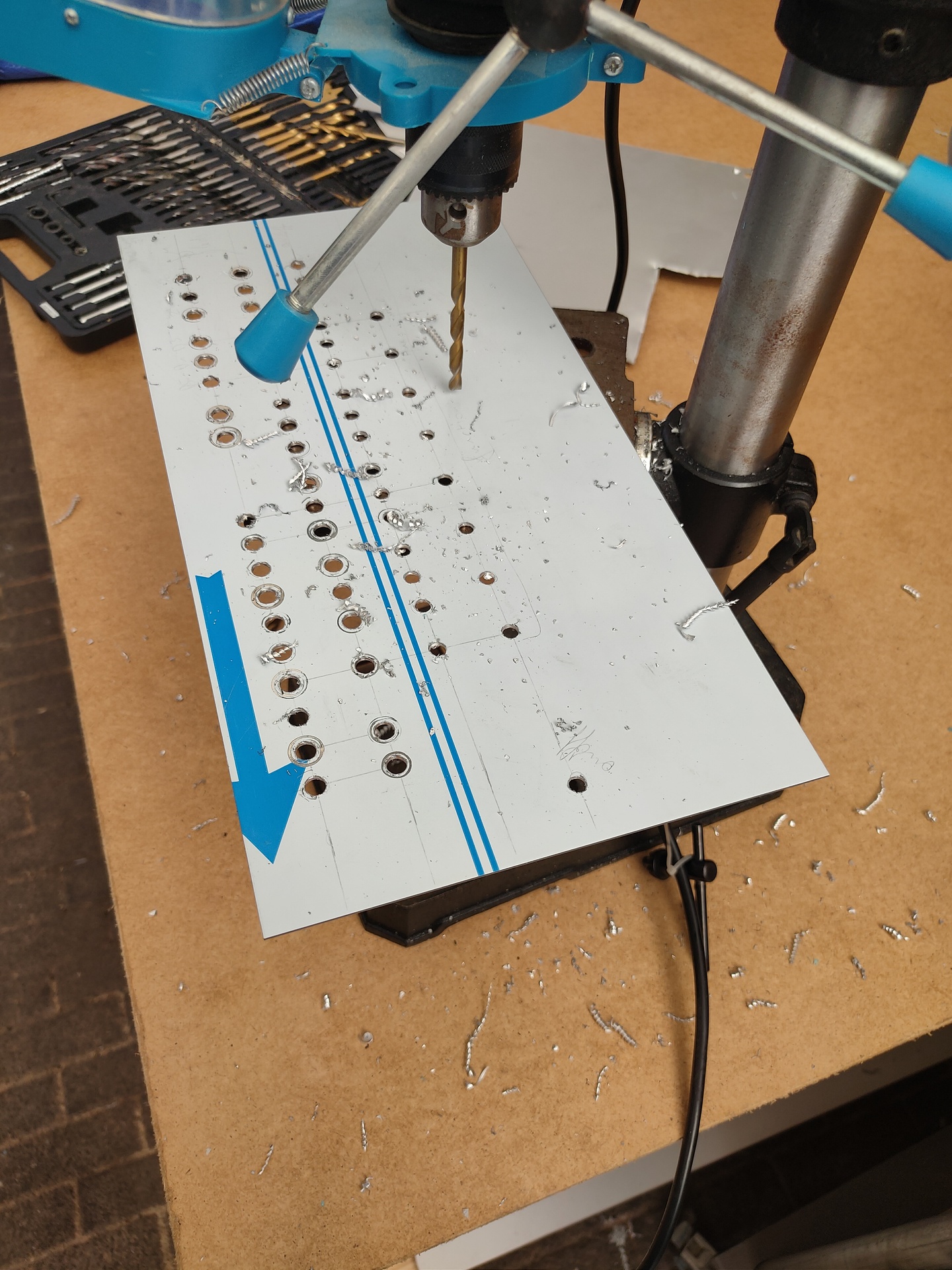
After a whole day soldering yesterday, ending up with a wire mess. Which didn’t work at the end…
Starting measuring some things, and create some test sketches (led blinky tests) I found out that the main problem was not having the red switches connected to GND. Blue switches where upside down, this was a easy fix. Because these are ON-ON switches, and where already connected to a common line. Then a mixup between D0 and D6 (wires crossed) And it is working! Made some lines and lettering on the frontplate after some playing around.
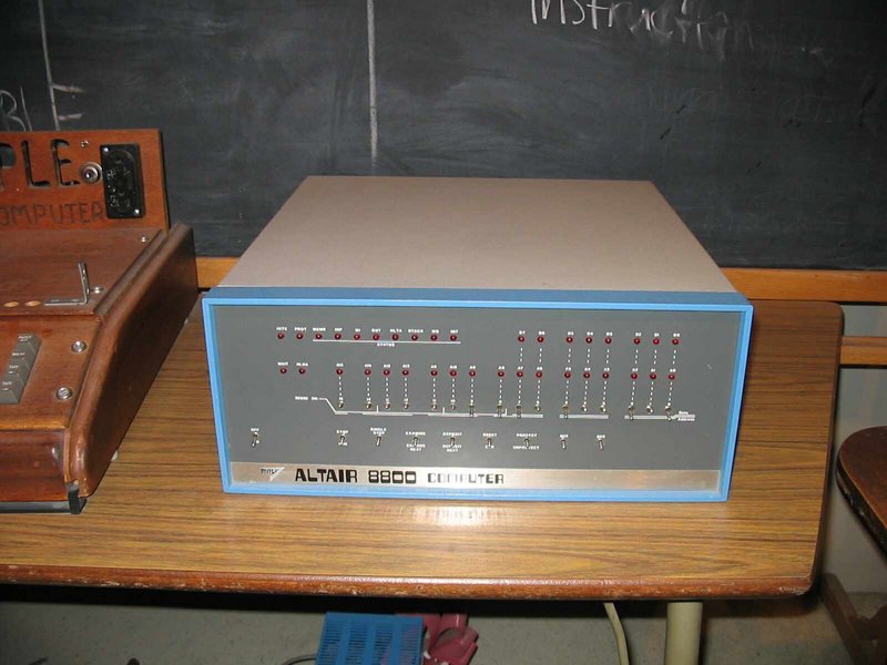
The Altair 8800 is a microcomputer designed in 1974 by MITS and based on the Intel 8080CPU. Interest grew quickly after it was featured on the cover of the January 1975 issue of Popular Electronics and was sold by mail order through advertisements there, in Radio-Electronics, and in other hobbyist magazines.
(picture from wikipedia)
UPDATE: 20220804 – Added Octal sheet
I alway loved the simple setup of this computer. There was no screen and no keyboard. Only later additions to the machine provided these.
One explanation of the Altair name, is that the name was inspired by Star Trek episode “Amok Time“, where the Enterprise crew went to Altair (Six).
There are only a few differences between the used 8080 CPU and the 8085 CPU of a machine i learned machinecode on.
See : https://www.henriaanstoot.nl/1989/01/01/8085-machinecode-at-school/
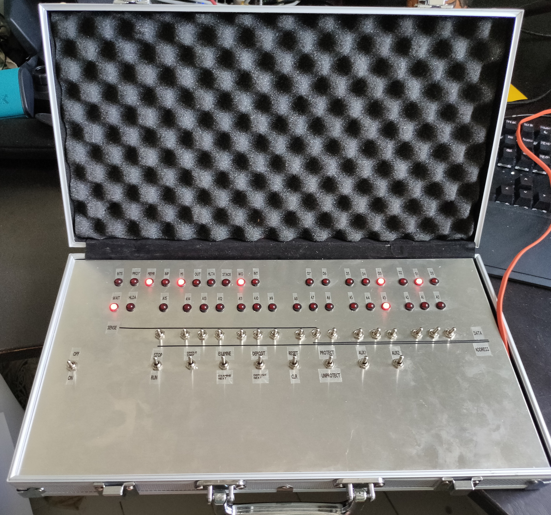
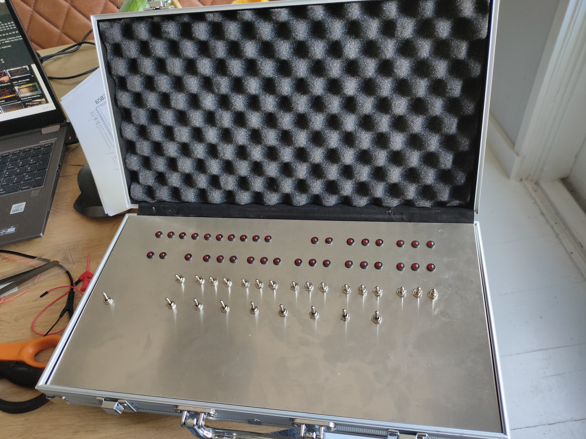
So for a really long time i wanted to have a Altair alike machine. There are do it yourself kits for sale. Which look like perfect relica’s and there are virtual machines and emulators. But i wanted to have the feeling of throwing the switches. You can find a emulator here (https://s2js.com/altair/)
So i bought the components, a poker case which can hold the machine. And started building today.
The backend is a arduino based emulator, but with real leds and switches! (https://create.arduino.cc/projecthub/david-hansel/arduino-altair-8800-simulator-3594a6)
Components and pokercaseDrillingFirst looks
Next to do:
Fix plate into case
Solder a LOT of wires and components!
Shall i get rid off the transitors and use darlington arrays?
Put lettering on the aluminium plate : Functions and Bus information.
Build a power connector in the case
And then … programming 🙂
UPDATE: 20220804 – Added Octal sheet
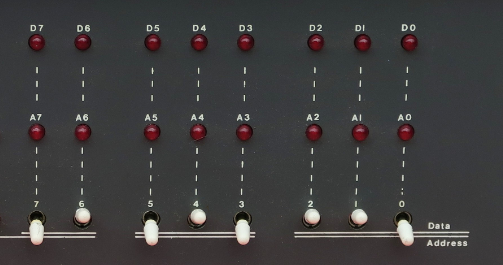
The Altair is a octal based machine, but i couldn’t find a opcode list in Octal. So i generated one. When entering a MOV D,M instruction for example, you have to enter x 0 1 0 1 0 1 1 0 using the switches Thats 126 in octal but most tables are in hex ( MOV D,M is 56, which is 0101 0110 but not that clear on the switches)
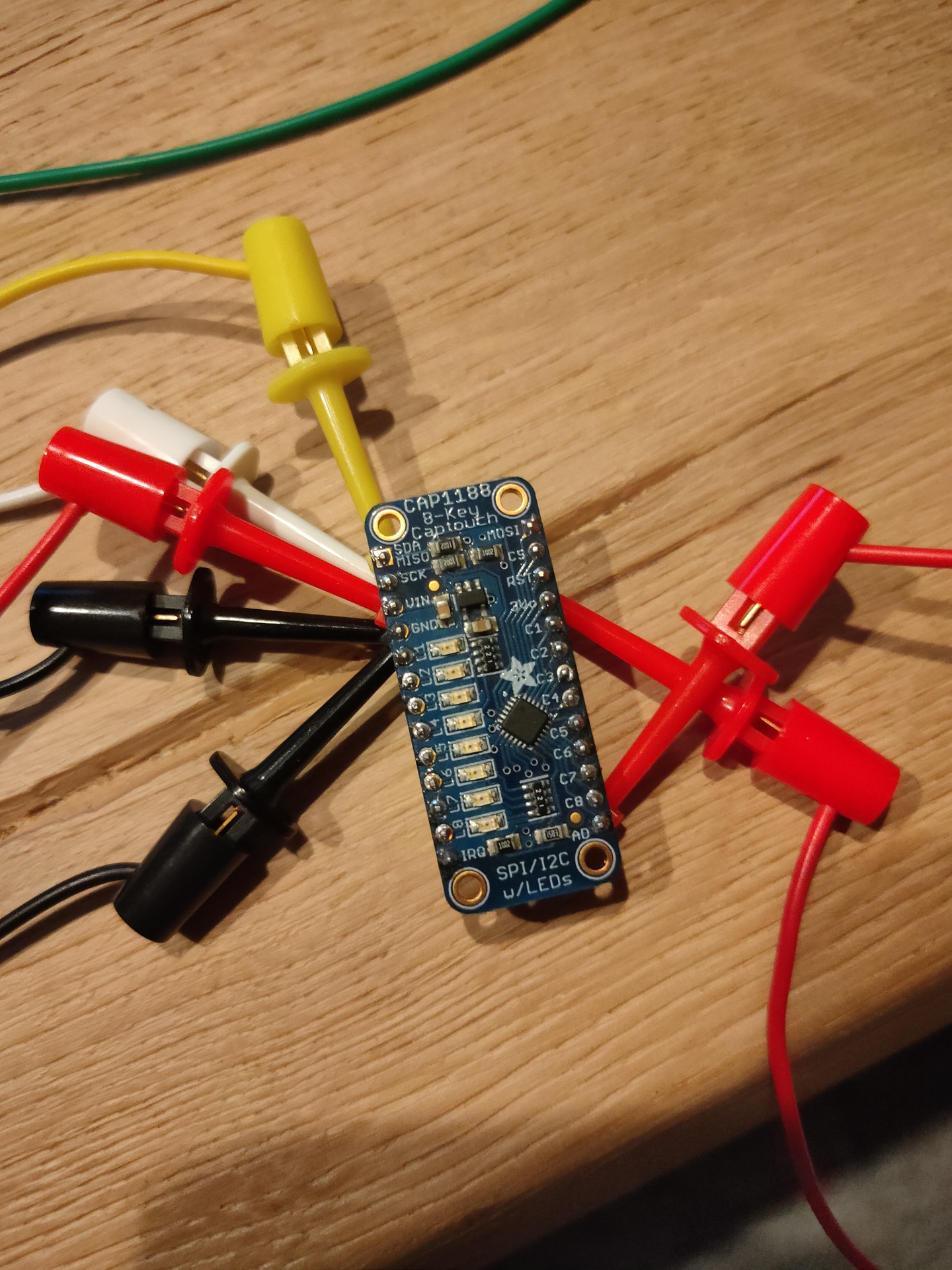
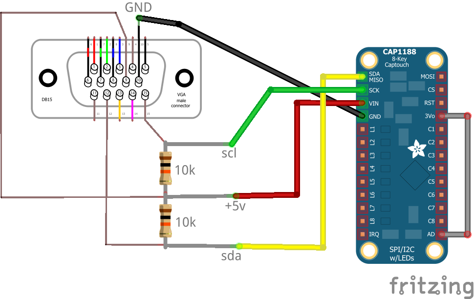
Way back in 2018 i was playing around with i2c and touch.
CAP1188 Multi touch sensor
I remembered that VGA was using i2c to get information from monitors like brand/type and connection information.
I managed to access the cap1188 up to my Laptop via VGA.
2018 Schematic i used to abuse vga …
The final python code i used to play with the variables and playing sound i can’t find. But below is the test code
#!/usr/bin/python

# NOTE: i did a address scan, now i have 3v3 connected to AD, so probably the address is 0x28 !!

import smbus

bus = smbus.SMBus(1)    # 0 = /dev/i2c-0 (port I2C0), 1 = /dev/i2c-1 (port I2C1)

DEVICE_ADDRESS = 0x29
DEVICEx = 0x10
DEVICE_REG_MODE1 = 0x00
DEVICE_REG_LEDOUT0 = 0x1d

#Write a single register
bus.write_byte_data(DEVICE_ADDRESS, 0x1f, 0x3F)

#Write an array of registers
#ledout_values = [0xff, 0xff, 0xff, 0xff, 0xff, 0xff]
#bus.write_i2c_block_data(DEVICE_ADDRESS, DEVICE_REG_LEDOUT0, ledout_values)
while True:

        print bus.read_byte_data(DEVICE_ADDRESS,0x10), bus.read_byte_data(DEVICE_ADDRESS,0x11) , bus.read_byte_data(DEVICE_ADDRESS,0x12), bus.read_byte_data(DEVICE_ADDRESS,0x13), bus.read_byte_data(DEVICE_ADDRESS,0x14), bus.read_byte_dat
a(DEVICE_ADDRESS,0x15), bus.read_byte_data(DEVICE_ADDRESS,0x16), bus.read_byte_data(DEVICE_ADDRESS,0x17)
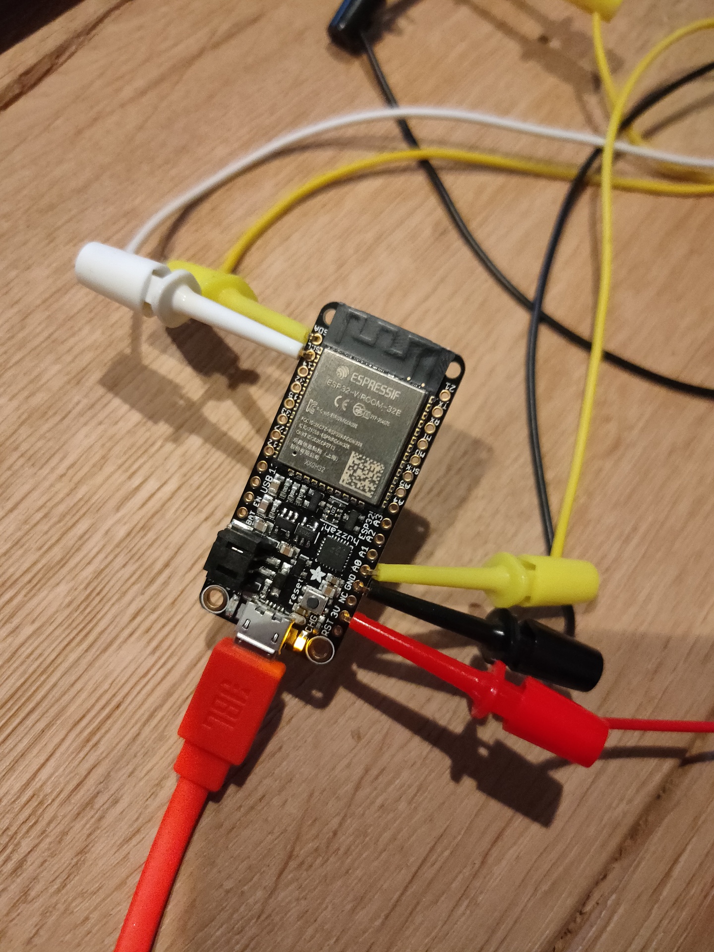
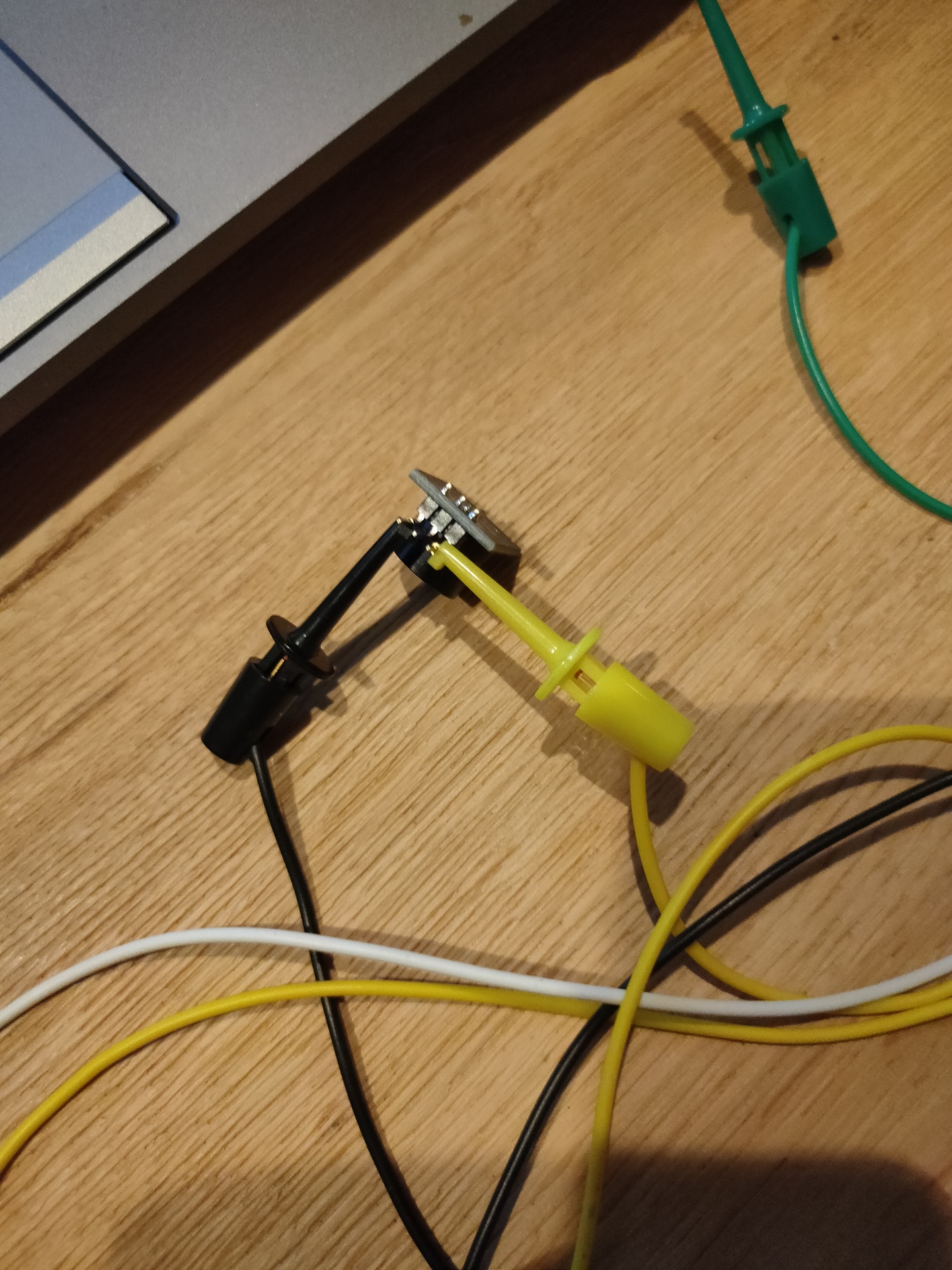
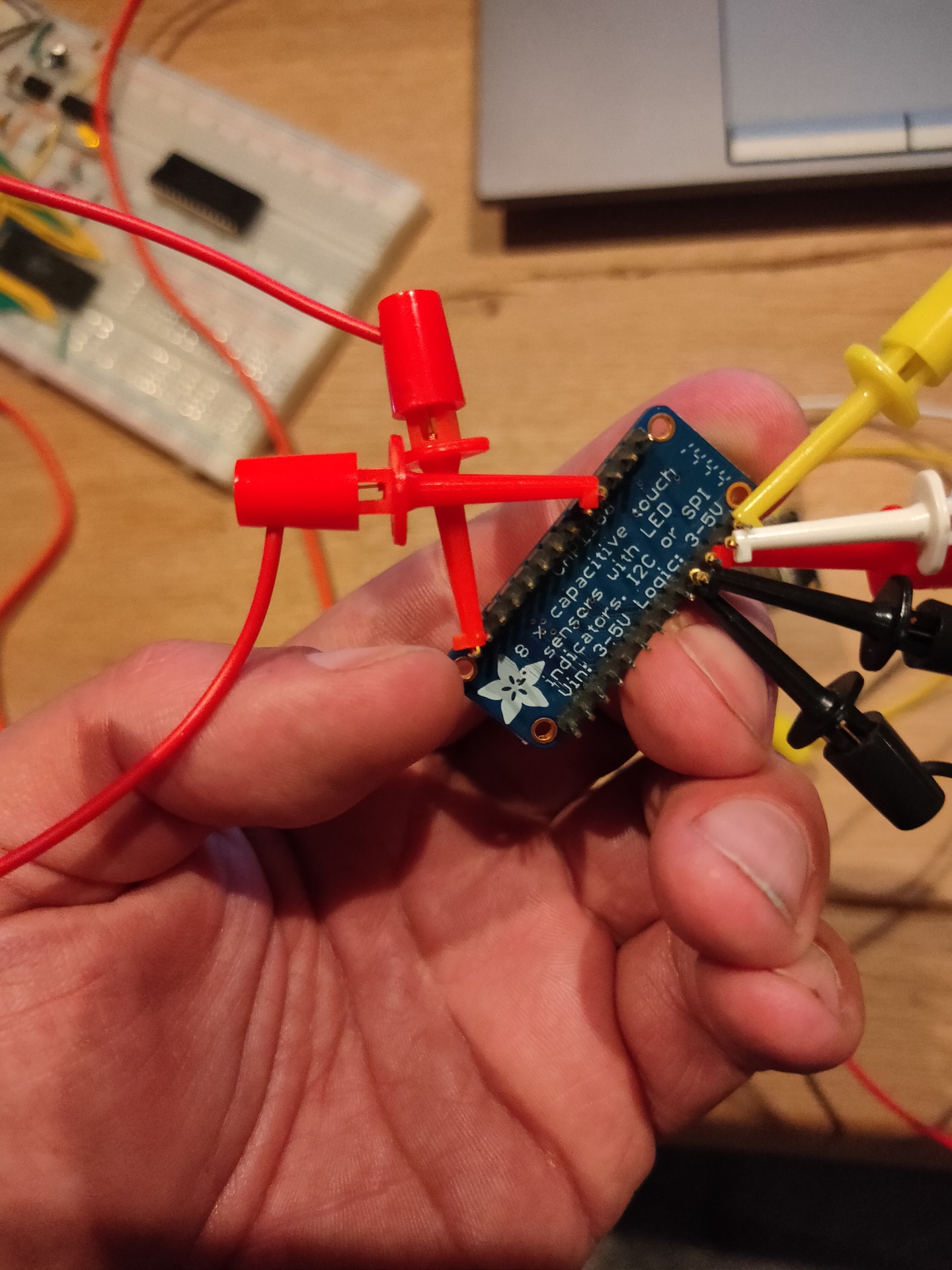
Today i connected the cap1188 to a ESP32 and a piezo buzzer.
ESP FuzzahBuzzerCAP1188CAP1188
/*** Based on below library ***/
/*** Changed pins and added sound ***/

/***************************************************
  This is a library for the CAP1188 I2C/SPI 8-chan Capacitive Sensor

  Designed specifically to work with the CAP1188 sensor from Adafruit
  ----> https://www.adafruit.com/products/1602

  These sensors use I2C/SPI to communicate, 2+ pins are required to
  interface
  Adafruit invests time and resources providing this open source code,
  please support Adafruit and open-source hardware by purchasing
  products from Adafruit!

  Written by Limor Fried/Ladyada for Adafruit Industries.
  BSD license, all text above must be included in any redistribution
 ****************************************************/

#include <Wire.h>
#include <SPI.h>
#include <Adafruit_CAP1188.h>

const int TONE_OUTPUT_PIN = 26;
const int TONE_PWM_CHANNEL = 0;
int freq = 0;


// Reset Pin is used for I2C or SPI
#define CAP1188_RESET  9

// CS pin is used for software or hardware SPI
#define CAP1188_CS  10

// These are defined for software SPI, for hardware SPI, check your
// board's SPI pins in the Arduino documentation
#define CAP1188_MOSI  11
#define CAP1188_MISO  12
#define CAP1188_CLK  13

// For I2C, connect SDA to your Arduino's SDA pin, SCL to SCL pin
// On UNO/Duemilanove/etc, SDA == Analog 4, SCL == Analog 5
// On Leonardo/Micro, SDA == Digital 2, SCL == Digital 3
// On Mega/ADK/Due, SDA == Digital 20, SCL == Digital 21

// Use I2C, no reset pin!
Adafruit_CAP1188 cap = Adafruit_CAP1188();

// Or...Use I2C, with reset pin
//Adafruit_CAP1188 cap = Adafruit_CAP1188(CAP1188_RESET);

// Or... Hardware SPI, CS pin & reset pin
// Adafruit_CAP1188 cap = Adafruit_CAP1188(CAP1188_CS, CAP1188_RESET);

// Or.. Software SPI: clock, miso, mosi, cs, reset
//Adafruit_CAP1188 cap = Adafruit_CAP1188(CAP1188_CLK, CAP1188_MISO, CAP1188_MOSI, CAP1188_CS, CAP1188_RESET);

void setup() {
  Serial.begin(9600);
  Serial.println("CAP1188 test!");
  ledcAttachPin(TONE_OUTPUT_PIN, TONE_PWM_CHANNEL);


  // Initialize the sensor, if using i2c you can pass in the i2c address
  if (!cap.begin(0x28)){
  //if (!cap.begin()) {
    Serial.println("CAP1188 not found");
    while (1);
  }
  Serial.println("CAP1188 found!");
}

void loop() {
  uint8_t touched = cap.touched();

  if (touched == 0) {
    // No touch detected
    return;
  }

  for (uint8_t i=0; i<8; i++) {
    if (touched & (1 << i)) {
      Serial.print(touched); Serial.print("\t");
      freq = (i * 100);
      ledcWriteTone(TONE_PWM_CHANNEL, freq);
      delay(100);
    }
  }

  Serial.println();
  delay(50);
}
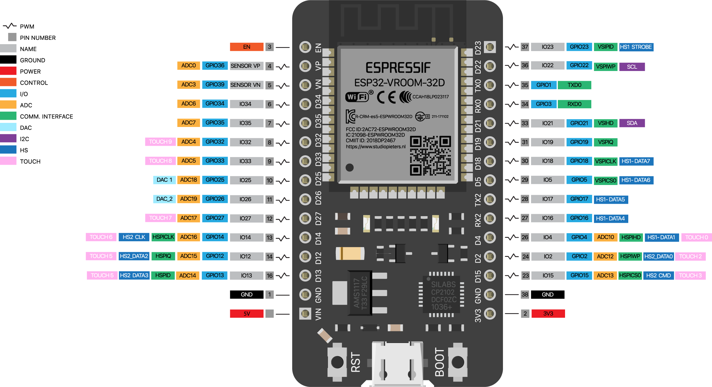
Finding the right pins or above pinout was the hardest part. The sketch reads the pins binary so value 129 is first and last bit.
Now i have to get the sound sounding a little better and add frequencies and fingersettings to the sketch to get a minimal electronic bagpipe. (V3 it is .. )
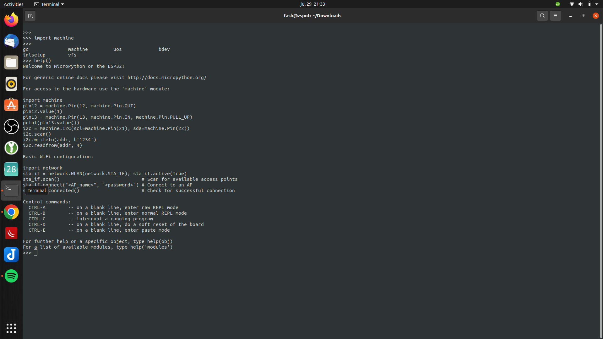
Download from https://micropython.org/resources/firmware/esp32-20220618-v1.19.1.bin
Test with
screen /dev/ttyUSB0 115200
Enter import machine or help()
Great up and running
Now we have to install a boot loader Use ampy to list files
#list boot
ampy -p /dev/ttyUSB0 ls
/boot.py

#get boot.py
ampy -p /dev/ttyUSB0 get boot.py
vi boot.py (create new)
#import esp
#esp.osdebug(None)
#import webrepl
#webrepl.start()

def connect():
    import network
    sta_if = network.WLAN(network.STA_IF)
    if not sta_if.isconnected():
        print('connecting to network...')
        sta_if.active(True)
        sta_if.connect('WIFISSID', 'WIFIPASS')
        while not sta_if.isconnected():
            pass
    print('network config:', sta_if.ifconfig())
Push the file
ampy -p /dev/ttyUSB0 put boot.py
Usage: ampy [OPTIONS] COMMAND [ARGS]...

  ampy - Adafruit MicroPython Tool

  Ampy is a tool to control MicroPython boards over a serial connection.
  Using ampy you can manipulate files on the board's internal filesystem and
  even run scripts.

Options:
  -p, --port PORT    Name of serial port for connected board.  Can optionally
                     specify with AMPY_PORT environment variable.  [required]
  -b, --baud BAUD    Baud rate for the serial connection (default 115200).
                     Can optionally specify with AMPY_BAUD environment
                     variable.
  -d, --delay DELAY  Delay in seconds before entering RAW MODE (default 0).
                     Can optionally specify with AMPY_DELAY environment
                     variable.
  --version          Show the version and exit.
  --help             Show this message and exit.

Commands:
  get    Retrieve a file from the board.
  ls     List contents of a directory on the board.
  mkdir  Create a directory on the board.
  put    Put a file or folder and its contents on the board.
  reset  Perform soft reset/reboot of the board.
  rm     Remove a file from the board.
  rmdir  Forcefully remove a folder and all its children from the board.
  run    Run a script and print its output.
Connect to serial console using screen
sudo screen /dev/ttyUSB0 115200
(use CTRL-A \ to exit)
Connect to wifi
import boot
connect()
Led blinky test, with below file named ledtest.py
import time
from machine import Pin
led=Pin(2,Pin.OUT)        #Internal led pin

while True:
  led.value(1)            #Set led turn on
  time.sleep(0.5)
  led.value(0)            #Set led turn off
  time.sleep(0.5)
Upload and run script
ampy -p /dev/ttyUSB0 put ledtest.py
import ledtest (without .py!)
Next todo: boot.py @boot ?!? Run custom python after booting. Connect display and play with drawing.
Tip: Install rshell !
sudo pip3 install rshell
fash@zspot:~$ rshell
Welcome to rshell. Use Control-D (or the exit command) to exit rshell.

No MicroPython boards connected - use the connect command to add one

/home/fash> autoconnect: /dev/ttyUSB0 action: add

/home/fash> ?

Documented commands (type help <topic>):
========================================
args    cat  connect  date  edit  filesize  help  mkdir  rm     shell
boards  cd   cp       echo  exit  filetype  ls    repl   rsync

Use Control-D (or the exit command) to exit rshell.
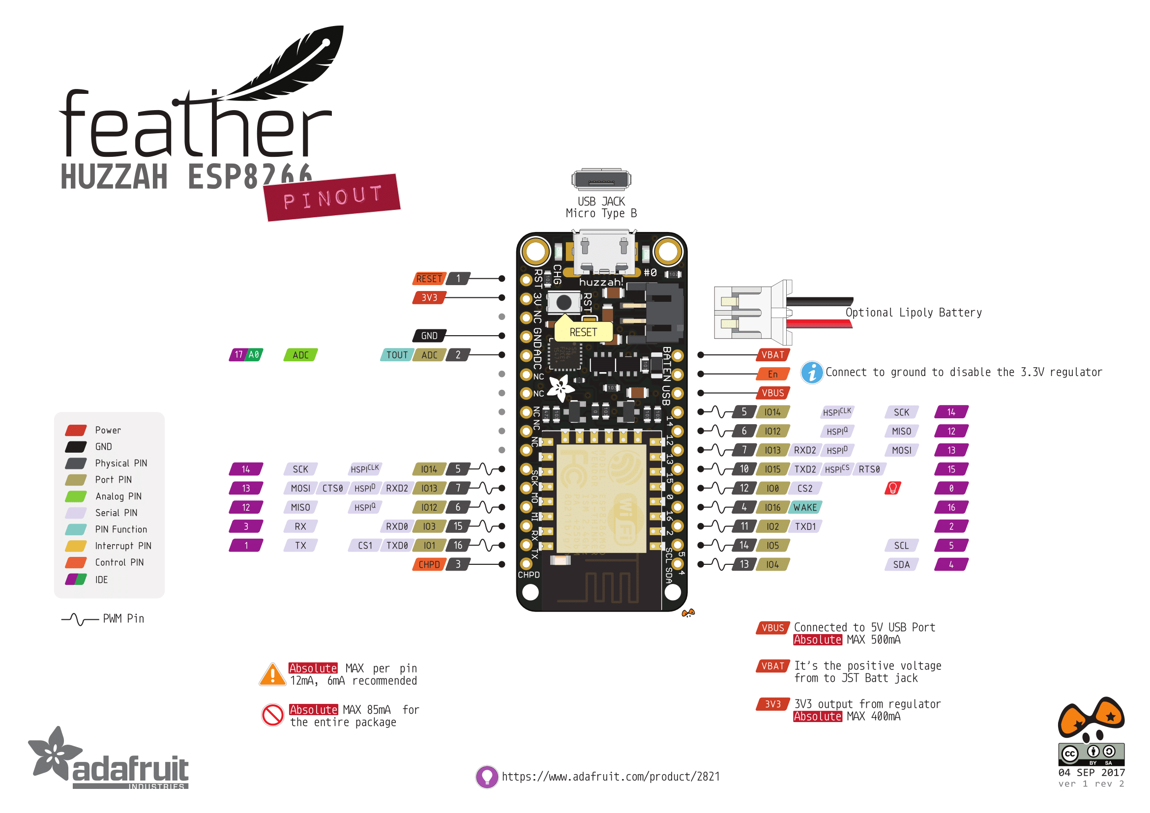
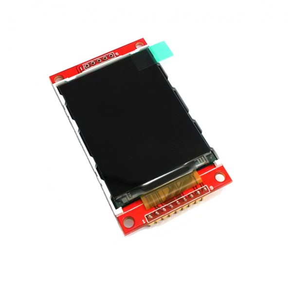
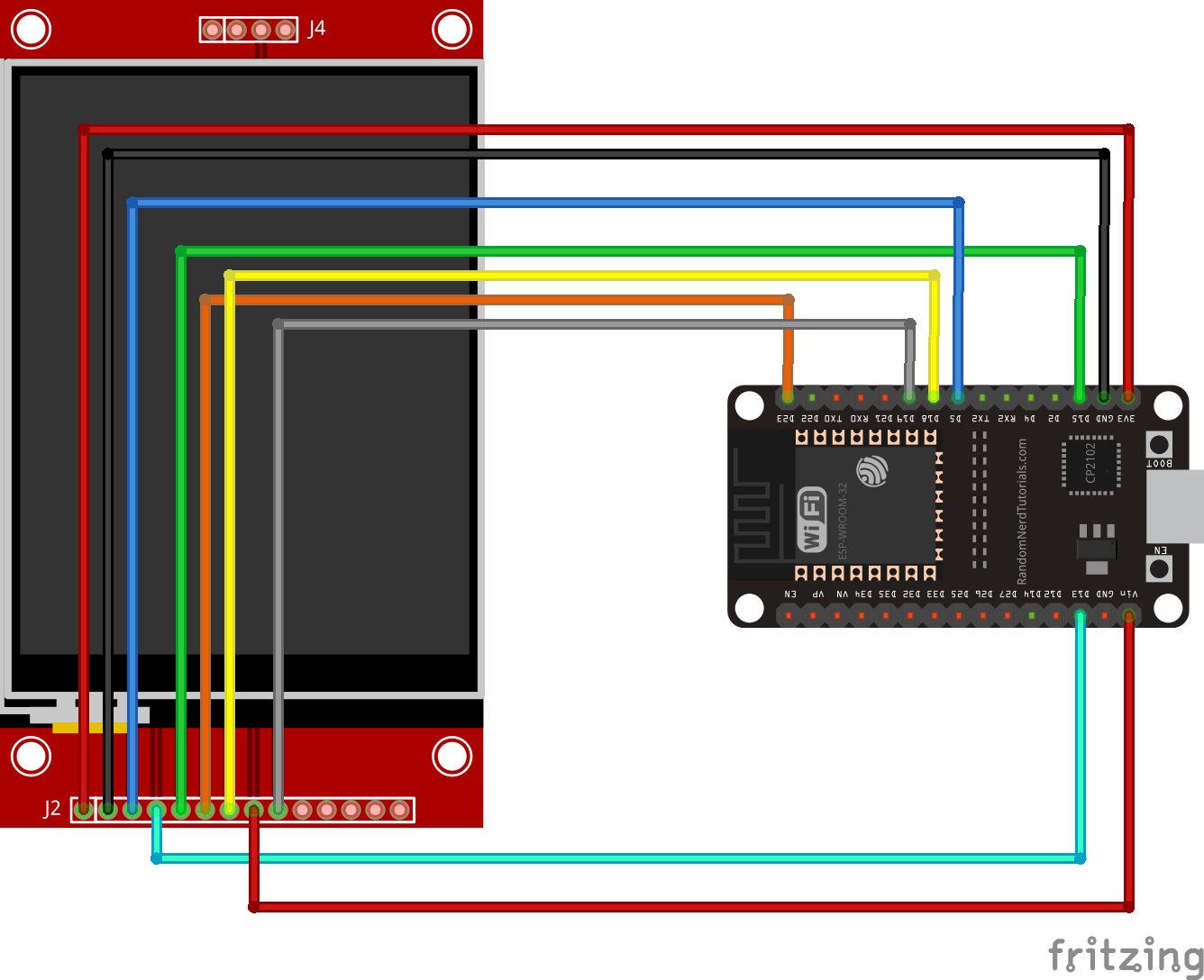
Connecting the display
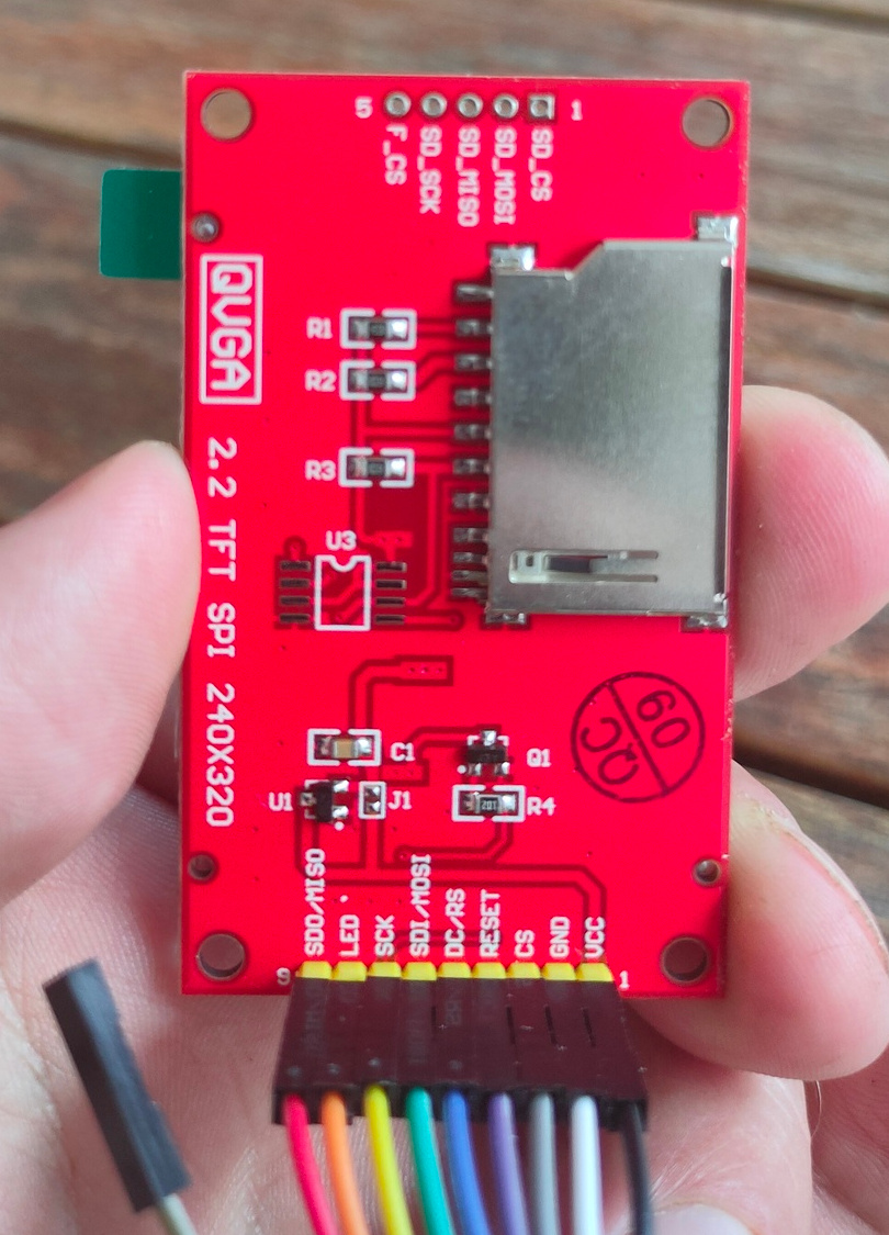
I’ve connected the display as above. Note the different connections on the display. Above fritzing part has connections for touch screen! The 4 or 5 pins on the other side are for sdcard functionallity.
Now you can use the library by editing a example like demo_bouncing_boxes.py
Add and change
# At the beginning of the file
import setupmydisplay.py

Futher down comment two lines and add your own setup

        # Baud rate of 40000000 seems about the max
        #spi = SPI(1, baudrate=40000000, sck=Pin(14), mosi=Pin(13))
        #display = Display(spi, dc=Pin(4), cs=Pin(16), rst=Pin(17))
        display = setup.createMyDisplay()
Upload to ESP32 and testing!
ampy -p /dev/ttyUSB0 put demo_bouncing_boxes.py
ampy -p /dev/ttyUSB0 put setupmydisplay.py
# connect and start
sudo screen /dev/ttyUSB0 115200
import demo_bouncing_boxes.py
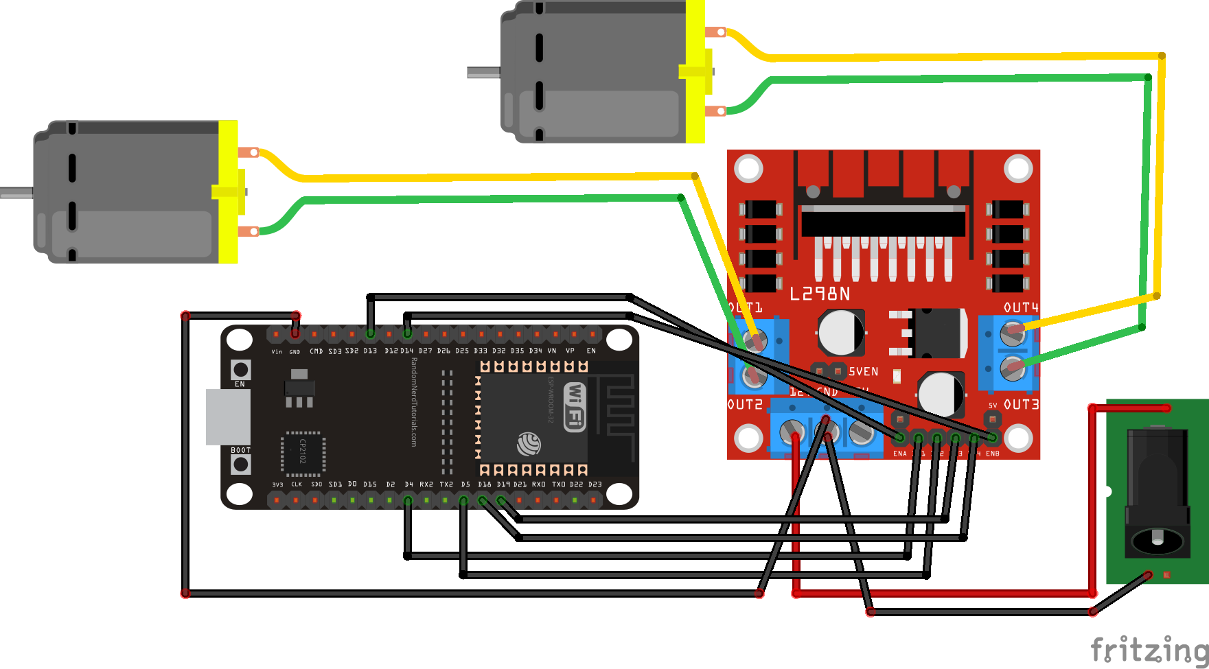
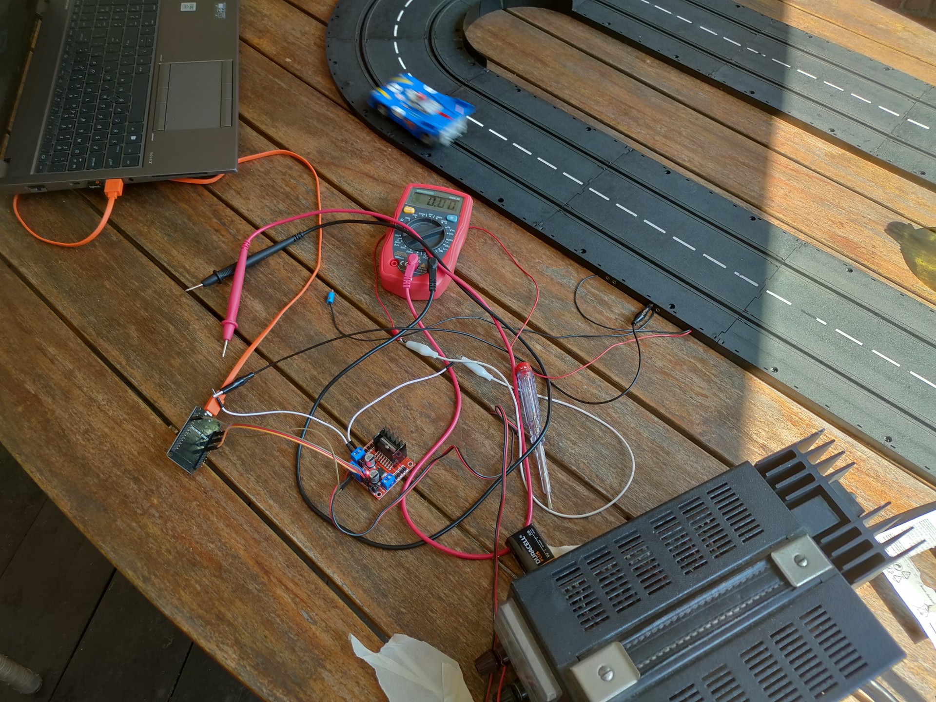
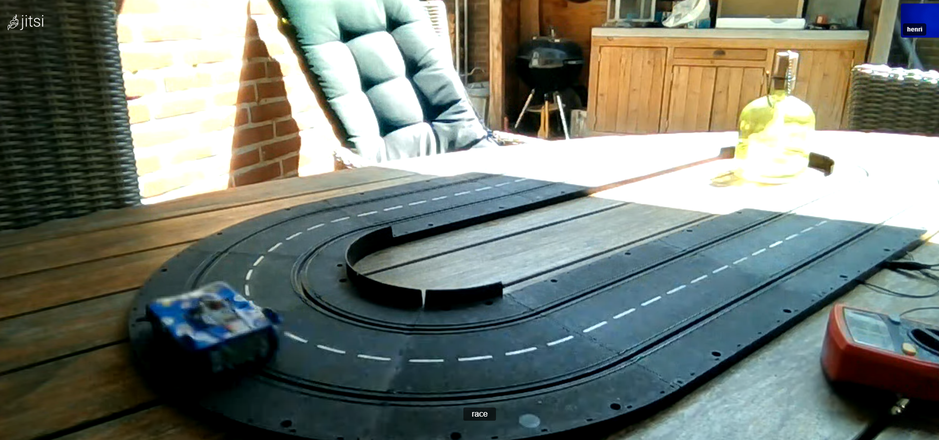
I got a vintage racetrack from a colleage a while back.
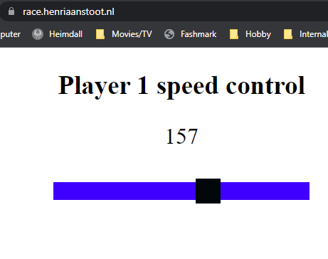
In the past i had some ideas controlling train or race tracks. For train tracks i wanted to write intelligent maneuver software. For a racetrack a web controllable race. Maybe with a webcam mounted on the car??
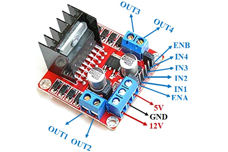
L298N – DC motor controller
So i bought a little DC motor controller (2 channels) and took a esp32.
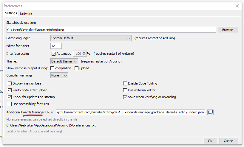
https://arduino.esp8266.com/stable/package_esp8266com_index.json,https://raw.githubusercontent.com/damellis/attiny/ide-1.6.x-boards-manager/package_damellis_attiny_index.json
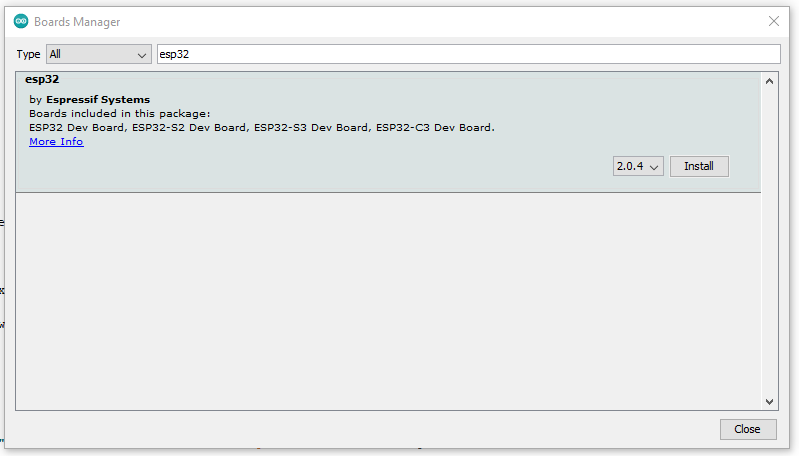
After that go to the Board manager.
Tools > Board: ..... > Board Manager
Search board, click and install.
NOTE: Some sketches require a specific version!
Select your board, and write/open you sketch.
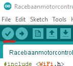
First thing to do is test compiling your sketch
Press the little button on the left
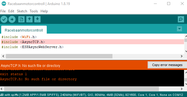
Libraries:
When you get a compile error like below, you are missing those libraries
Goto tools > Manage libraries
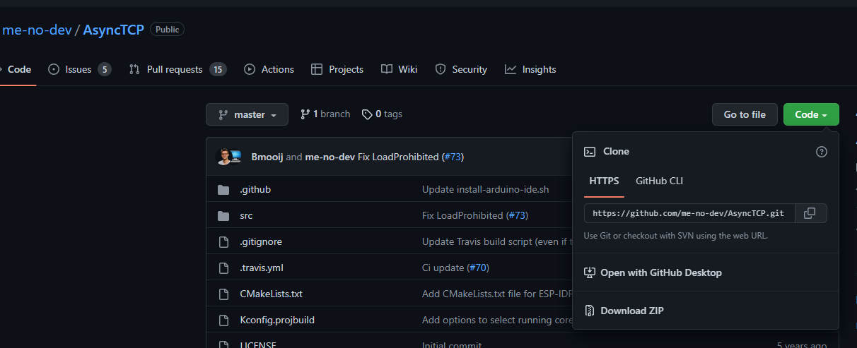
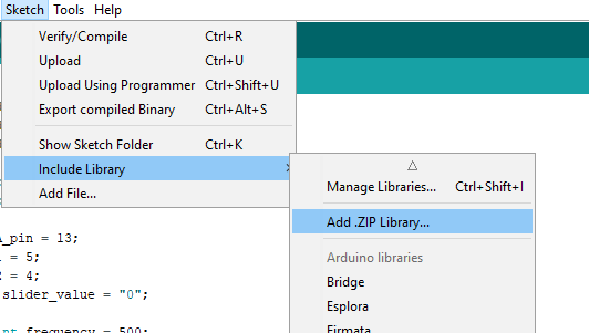
Search for your needed library, sometimes there are multiple which look alike. This is a trial and error approach. Sometimes it doesn’t exists and you need to upload a zip containing the library. (Sketch > Include Library > Add .zip library
Downloading a zip containing the library
Adding the library zip file
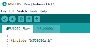
When looking at the first lines of you sketch, there are include statements like:
But sometimes there are statements without the < > characters. Then it will be a included file just for your sketch.
Note the second tab MPU6050x.h which contains specific code only for this sketch.
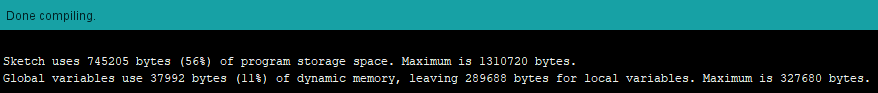
Redo a test recompile using the tic icon again.
Everything okay? .. Select the correct port in Tools > Port And press the Arrowright icon to upload/flash. Note: sometimes you have to hold a button or press a little flash button on your device to flash.
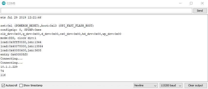
esptool.py v3.3
Serial port COM8
Connecting.....
Chip is ESP32-D0WDQ6-V3 (revision 3)
Features: WiFi, BT, Dual Core, 240MHz, VRef calibration in efuse, Coding Scheme None
Crystal is 40MHz
MAC: c8:c9:a3:f9:02:d0
Uploading stub...
Running stub...
Stub running...
Changing baud rate to 921600
Changed.
Configuring flash size...
Flash will be erased from 0x00001000 to 0x00005fff...
Flash will be erased from 0x00008000 to 0x00008fff...
Flash will be erased from 0x0000e000 to 0x0000ffff...
Flash will be erased from 0x00010000 to 0x000c7fff...
Flash params set to 0x022f
Compressed 18880 bytes to 12992...
Writing at 0x00001000... (100 %)
Wrote 18880 bytes (12992 compressed) at 0x00001000 in 0.3 seconds (effective 482.8 kbit/s)...
Hash of data verified.
Compressed 3072 bytes to 128...
Writing at 0x00008000... (100 %)
Wrote 3072 bytes (128 compressed) at 0x00008000 in 0.0 seconds (effective 627.7 kbit/s)...
Hash of data verified.
Compressed 8192 bytes to 47...
Writing at 0x0000e000... (100 %)
Wrote 8192 bytes (47 compressed) at 0x0000e000 in 0.1 seconds (effective 1087.9 kbit/s)...
Hash of data verified.
Compressed 750976 bytes to 477779...
Writing at 0x00010000... (3 %)
...
...
...
Writing at 0x000bb633... (93 %)
Writing at 0x000c0acd... (96 %)
Writing at 0x000c6649... (100 %)
Wrote 750976 bytes (477779 compressed) at 0x00010000 in 6.3 seconds (effective 947.4 kbit/s)...
Hash of data verified.

Leaving...
Hard resetting via RTS pin...
Most of the boards you can connect via micro-usb. Sometimes you need adaptors like:
Attiny programmerttl uart interface
TIPS ‘n tricks:
Open same file in another editor, so you can compare for example the top (declarations) and futher down the code. Else you could be ending up scolling up/down all day long. And probably forgetting how a variablename was exacly spelled.
Use serial monitor! When debugging this is a valuable tool. Enter statements into you code, which prints debugging info to a serial monitoring window when your device is still hookedup to your PC.
Example printing connected IP and values registered
Other obvious tips: Add comment lines (documentation) Use variable names which make sense! ( Hard to find what aaaa() does, or what tmp-a is, but LastTempValue says a lot more)
MCH2022 is a nonprofit outdoor hacker camp taking place in Zeewolde, the Netherlands, July 22 to 26 2022. The event is organized for and by volunteers from the worldwide hacker community.
Knowledge sharing, technological advancement, experimentation, connecting with your hacker peers and hacking are some of the core values of this event.
MCH2022 is the successor of a string of similar events happening every four years since 1989. These are GHP, HEU, HIP, HAL, WTH, HAR, OHM and SHA.
I’ve bin to several of these big events. Besides these big events are many different smaller events (wannull, ne2000 etc).
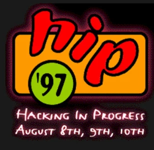
First one i’ve been was HIP97. I went with Bigred at that time. I had to get the tickets at that time, he didn’t had a handle at that time. It was Monique who came up with his new nick.
After HIP97 there was HAL2001 WTH2005 and OHM2013 which i was present. HAL2001 the whole ICEcrew was present, WTH a part of them, OHM a few and i was with a few PRUTS friends.
Now i was with my girlfriend, AND with Bigred again! Loads of fun and memories. Had not seen Bigred since a inbetween hacker party at my place. So ’97 and now ’22 .. jeez 25 years!
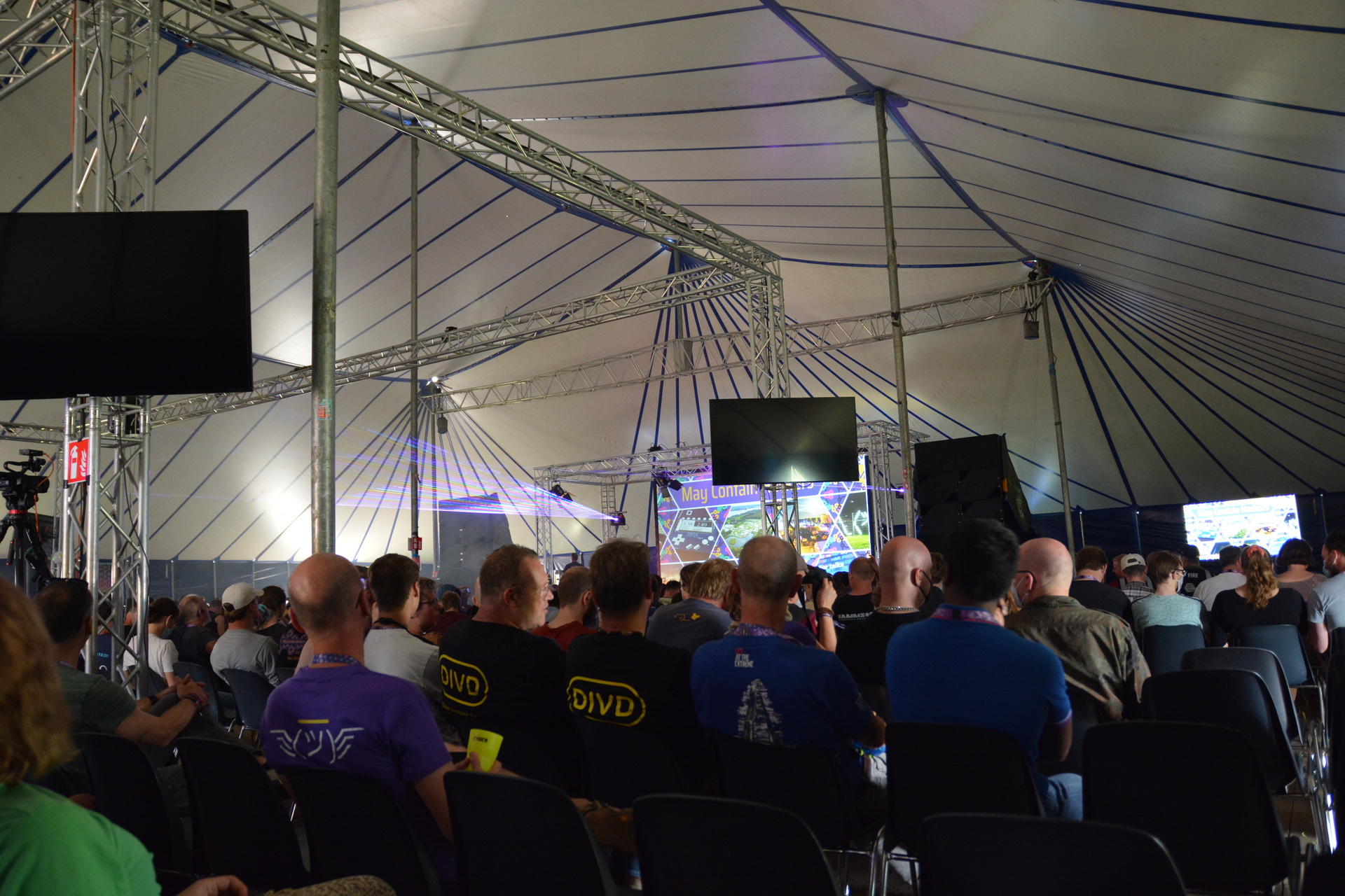
So MCH, it was great again. Loads of stuff to do and to see. Weather was … okay. Two days where really hot, one day some light rain but a load of wind. Our neighbours tent collapsed, beer tents where reenforced. First campsite with a supermarket! Music stage was awesome, lasers and fire!
I went to a lot of talks, even my girlfriend found some she was interested in.
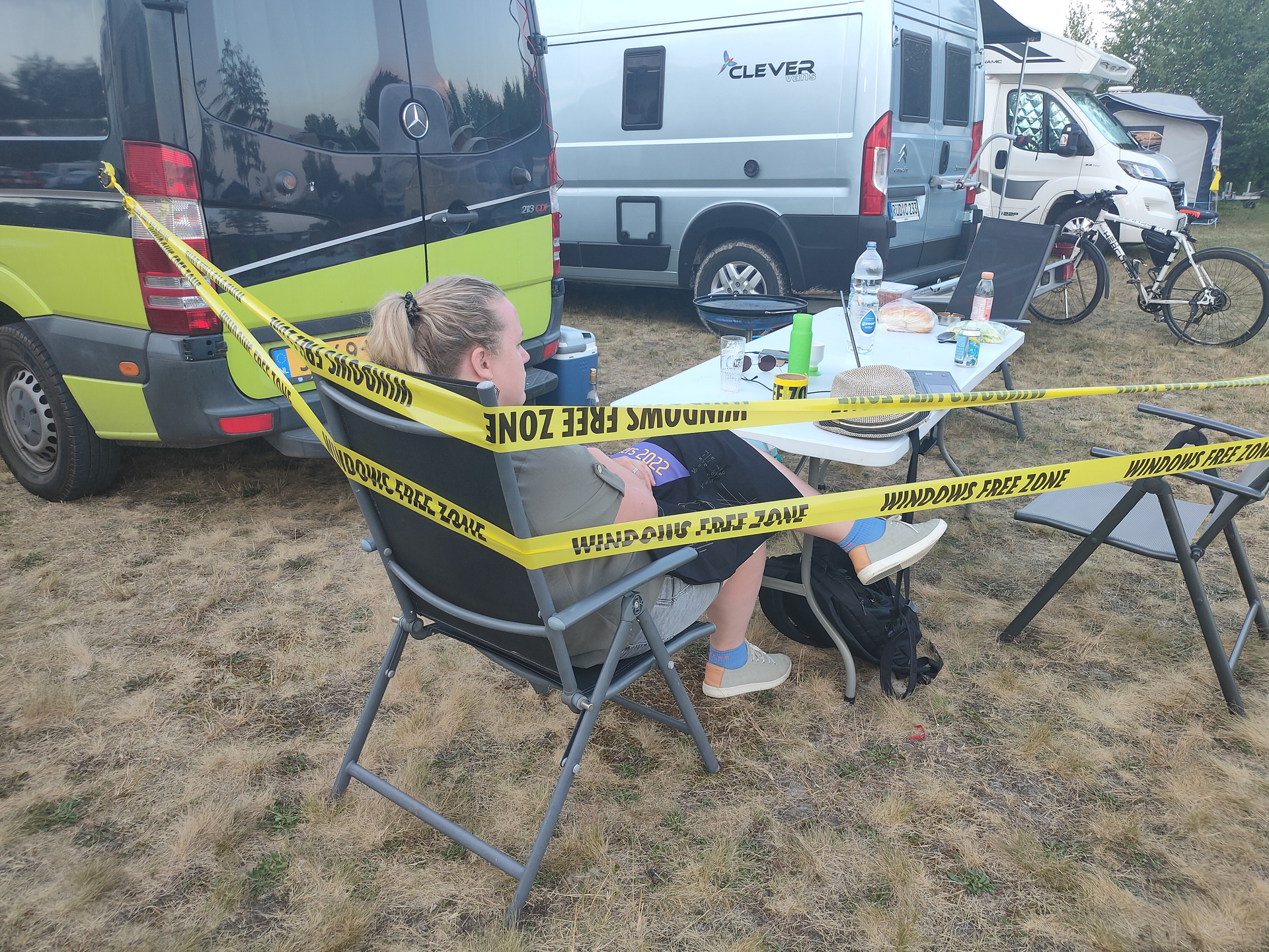
OpeningAt nightLast time my tapeTinkeringtar cz ourstuff.tgz
This was the last time i’ve brought my “Windows free zone tape” This big roll of tape was used on many occasions. I got this roll somewhere < 2000, I did a search but couldn’t find anything mentioning it on the web. Maybe some archive.org entry?
Starting a Home Computer Museum (which i almost did in the past)
streaming 360 video (going to try this with my Vuze XR Camera)
Non-Euclidean Doom: what happens to a game when pi is not 3.14159… (Really enjoyed this one)
Hacking the genome: how does it work, and should we?
And more
Besides the talks i’ve done some workshops:
Micropython on the badge (see my other post)
Kicad – PCB designing
Meanwhile we where looking at all the villages and hackerspaces. Loads of interesting people to meet. Like our neighbour two tents futher, he was also a home-brewer, and he brought a minifridge with beer taps connected to it.
When back at our tent or Bigreds Campervan, we talked about differences now and then. New technology, what we’ve been upto in the last years and tinkering, loads of tinkering.
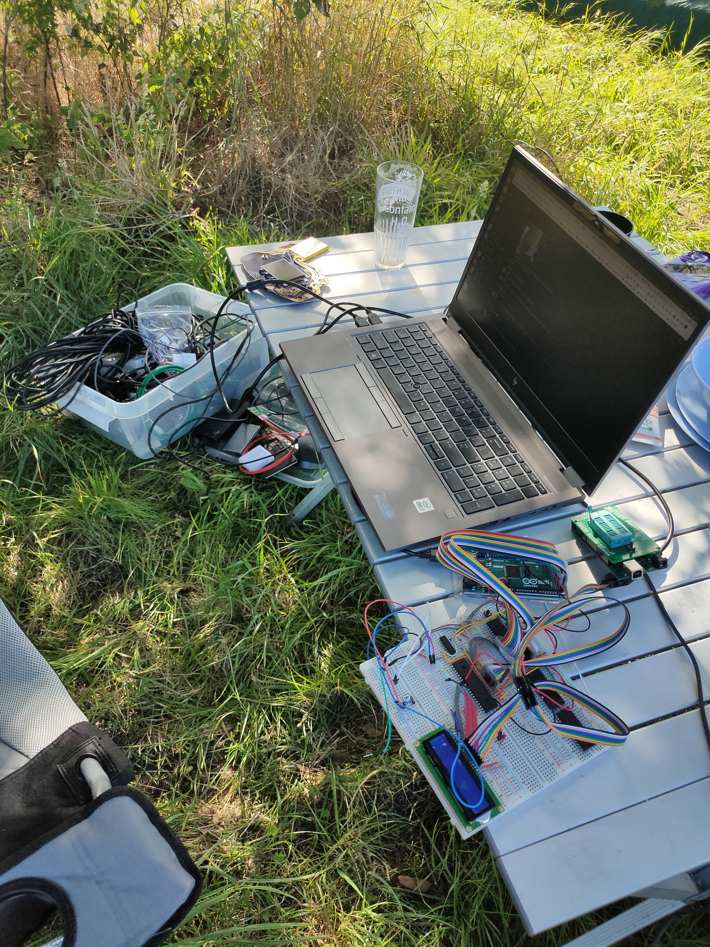
I’ve brough a big plastic container with .. ehh “things to do ….”
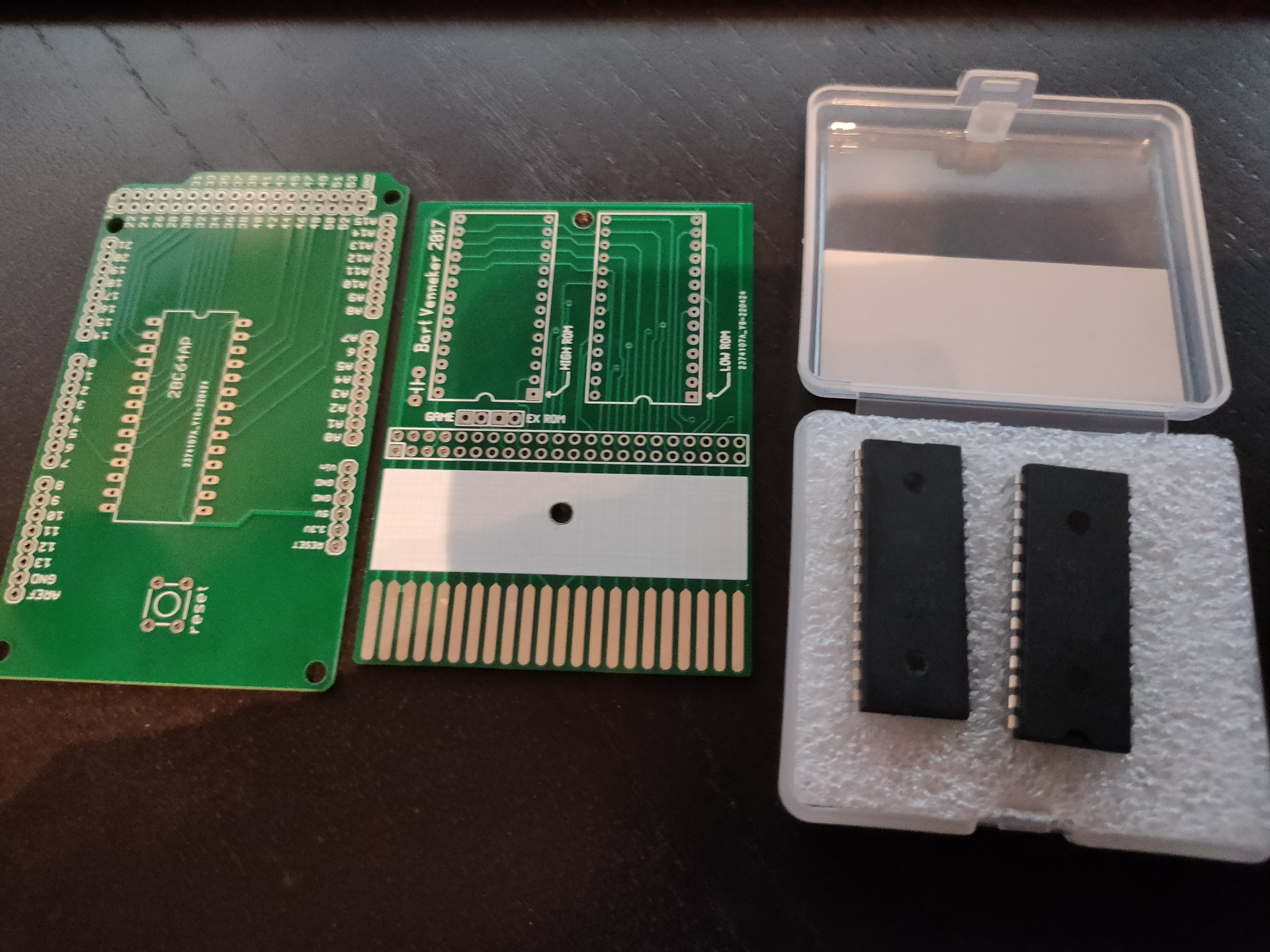
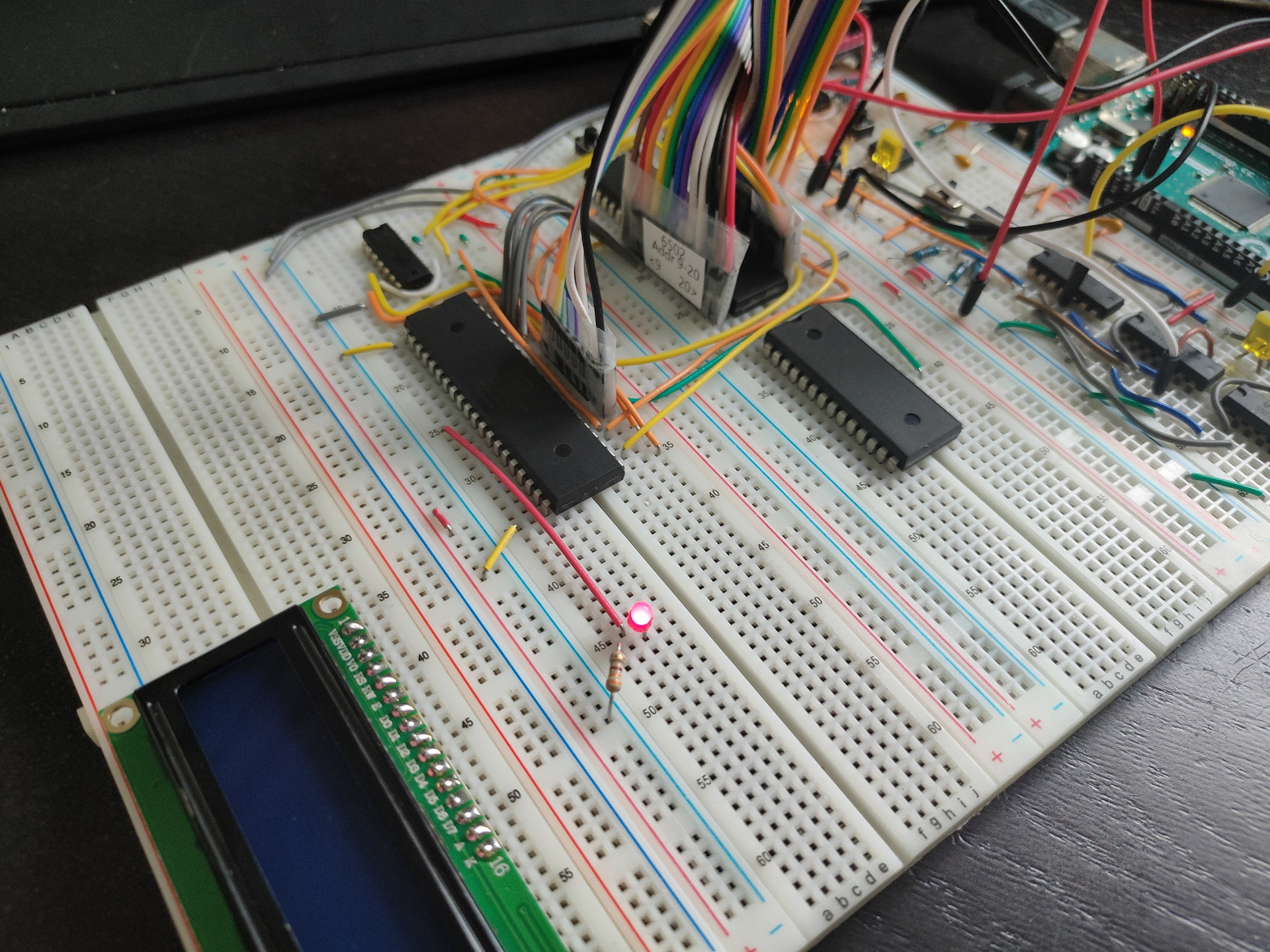
My 6502, bigred helped me debugging the 16*2 display. (Luckily his campervan was packed with electronics!) We cannibalized one of his projects for a display, and re-flashed his eeprom programming arduino to test my display. ( The arduino i had to reflash later to program a rom he had given me for my 6502. ) Other toys he gave me: Print for the programmer, and a C64 Cartridge print for Exrom and Game.
Mini C64 with a little screen and raspberry zero.
5050 ledstrip (didn’t had time to reprogram this for our mood-light)
Handheld gamehat: Bigred found some old games he played when he was young
Mikrotik router, because i wanted to make a dmz for my girlfriends laptop. (MS)
Playing around with my Vuze XR camera
Huskycam, which i’m planning to use on a racetrack
DVB-T DAB FM Stick, got some hints and tips from Bigred. (Note to myself … fix the antenna!)
My Arduino touch bagpipe player with i2c
The wifi deauther, which has a display which i wanted to use to make a programmable clock for my 6502. Using a rotary encoder and the display to control the speed in Hz.
I spend many hours playing with the Badge and Kicad
Wrote some 6502 assembly, arduino sketches, php, bash and micropython.
While playing around with the badge i got some things working easily. Spinning logo and blinky leds. Next goal to achieve was, to get the gyroscope to control the angle of spinning. Most of the code worked, but the gyro values stayed zero! (After many hours …. you have to start/enable the chip/measurements on the bno055 first! .. duh! )
I didn’t had my dev directory from my main battlestation synced in my nextcloud, so changing things for the 6502 was a b*tch. Used vasm and acme to generate a bin file to use to fill the rom. Didn’t like the eeprom programmer program, because i could not easily check the rom contents. Have to look into that later on.
While learning to use Kicad, which i only had been using to draw schematics (besides fritzing) , i learned to create a pcb. Which gave me the idea to make a print for the power-on-reset for the 6502. Which is going to be the first PCB by ordering, instead of the old skool messing around with DIY print making. (see next post)
….. Oh, why my display was not working? I even connected my 8bit logic analyzer to the pins of the display.
Everything was correct. But i didn’t use a variable resistor for the contrast. Just a simple resistor i could find. Luckily … bigreds stash. All those hours debugging, all for one resistor! (I have to mention, we had a suspicion halfway. But it was too hot and we where too lazy to go to Bigred’s campervan, to get a potentiometer. )
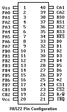
65c22 connected, new data, and address-bus ribboncables!
First led on Register B blinking!
Notes: Temporary display wil be 2×16 Chars. Ram in place, but not connected (is emulated by the Arduino Mega at the moment) Rom is somewhere halfway the atlantic ocean .. still waiting on that one. Ben Eatons clock module is disconnected, i’m using the Arduino as programmable clock right now. (There wil be a little display and a rotary encoder to set clock speed.)
lda #$ff ; all bits
sta $6002 ; set direction (out) for B register
lda #$80 ; set 1 bit
sta $6000 ; set register B
lda #$00 ; reset bit
sta $6000 ; set register B
jmp $8005 ; jmp to bit set part
Almost … friday will be the day i’ll attend May Contain Hackers. Besides the awesome villages and talks.
UPDATE: 20220727 UPDATE: 20220812
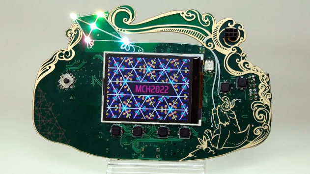
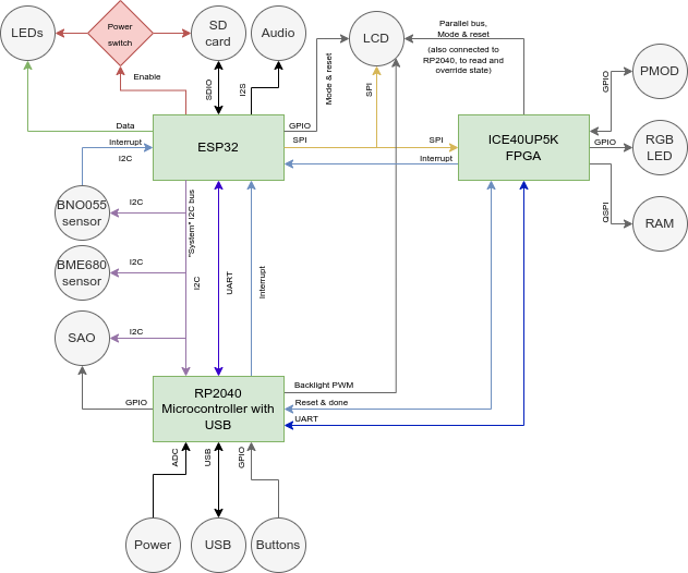
You get a hackable badge, this one is more amazing as previous versions.
I can’t wait to have a go at this cool gadget. I personally could do without the pcb fancy design.
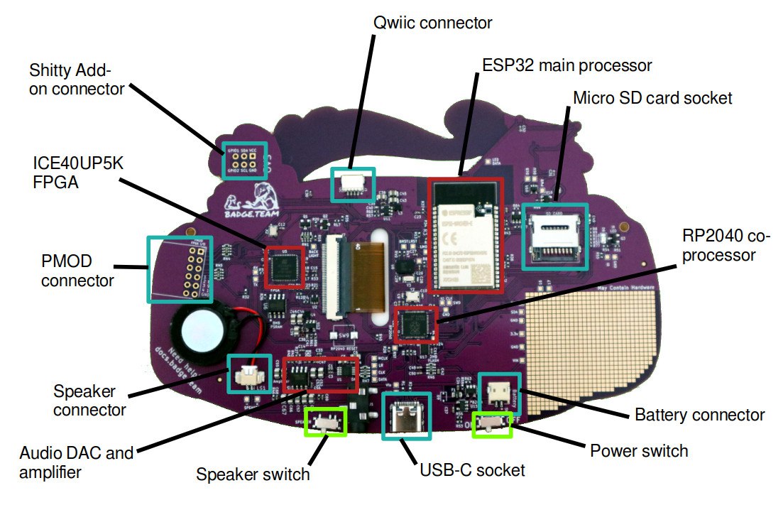
Espressif ESP32 Wrover-E with 16MB of flash storage and paired with 8MB of PSRAM, for front-end badge computing and compatibility with the badge.team ecosystem back to the 2017 SHA badge.
Lattice ICE40UP5K FPGA for hardware-accelerated graphics and user FPGA hardware designs.
Raspberry Pi RP2040 for advanced USB communication and board management.
2Ah LiPo battery to give you a full day of fun on a charge.
16-bit DAC with stereo output to headphone socket, onboard mono speaker.
ILI9341 2.2 inch TFT display with a 240 by 320 pixel resolution.
Bosch BNO055 orientation sensor.
Bosch BME680 environmental sensor.
The usual array of addressable LEDs.
SAO and Qwiic expansion connectors, FPGA PMOD expansion, plus onboard prototyping area.
Downloadable apps, micro python, Arduino ide programming. All kinds of GPIO pins, leds buttons, sound. Check out https://hatchery.badge.team/
You can play with this virtually here! https://wokwi.com/projects/335445228923126356
So much potential! Great start for a DIY project.
I won’t post about the workings, thats all well documented online. I shall post about the hacks/findings i personally did.
UPDATE: 20220727 Made a micropython program to keep your NameTag level to the ground (Better version)
UPDATE: 20220812
Someone made a 8bit logic analyser using the pmod connector !
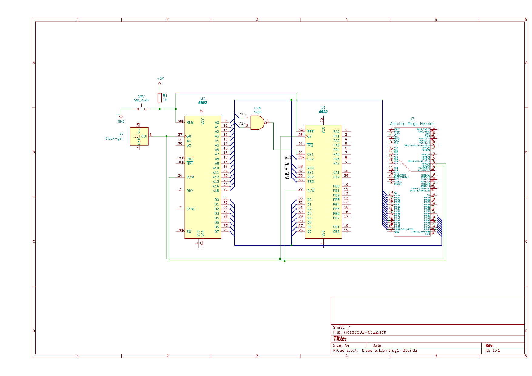
Due to eeproms being scarce, i’m going to use a arduino as Rom emulator. Below is a test setup i’m going to build.
Made the drawing in Kicad.
KiCad is a free software suite for electronic design automation. It facilitates the design and simulation of electronic hardware. It features an integrated environment for schematic capture, PCB layout, manufacturing file viewing, SPICE simulation, and engineering calculation.
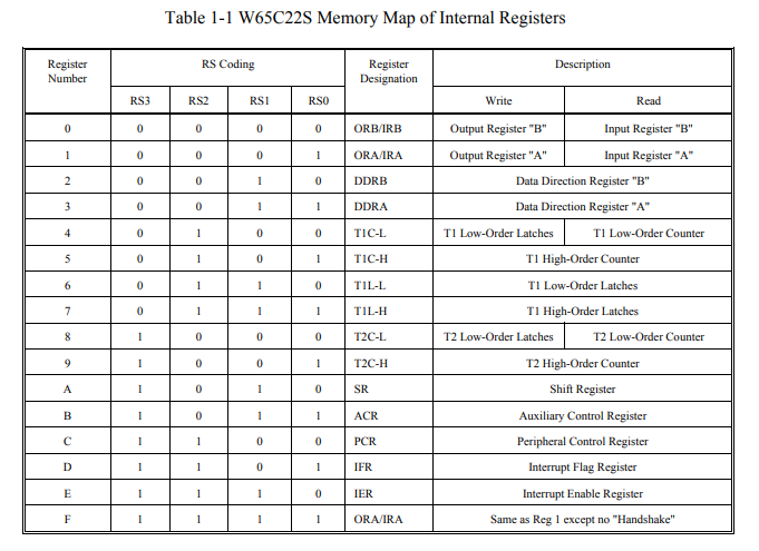
Memory assignment:
$8000-FFFF - Rom
$4000-7FFF - Ram ?
$2000-3FFF - Multiple times the 6522 *
$0000-???? - Ram probably

* This is due to the fact i am only using Address lines: 0,1,2,3,13,14,15
"If something is worth doing, it's worth overdoing."