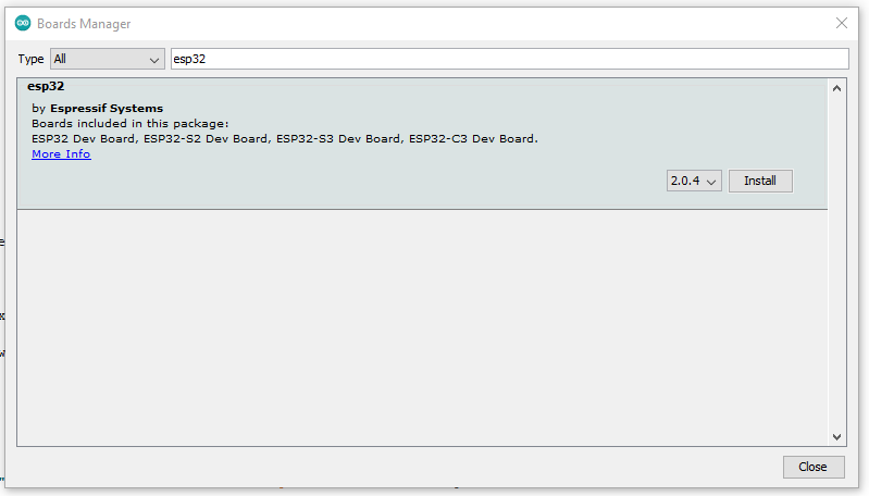
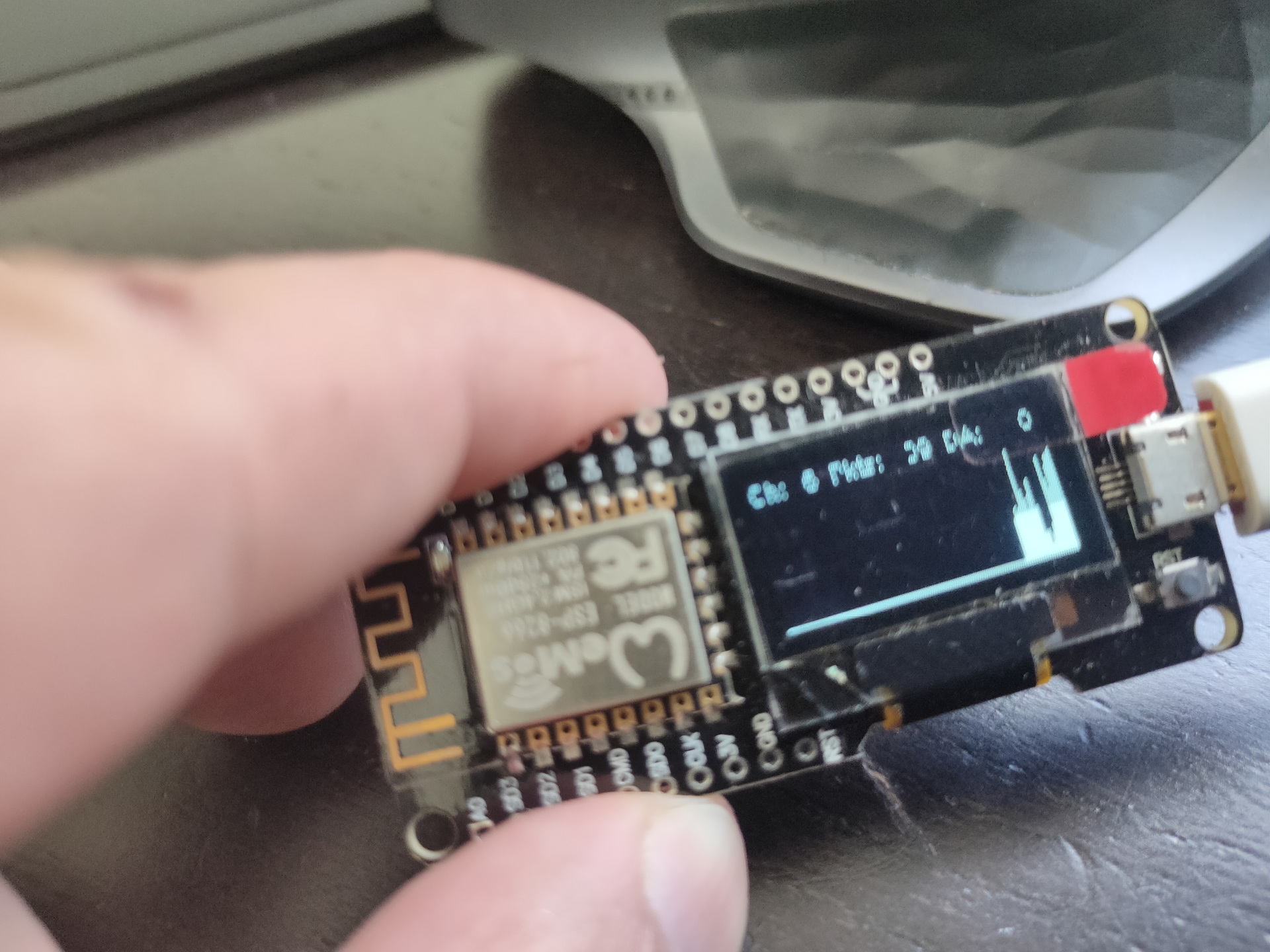
This exercise is to get a micropython dev environment with a graphical display.
pip3 install esptool adafruit-ampy
Erase board (use correct tty device!)
esptool.py --chip esp32 --port /dev/ttyUSB0 erase_flash
Flash using
esptool.py --chip esp32 --port /dev/ttyUSB0 --baud 460800 write_flash -z 0x1000 esp32-20190125-v1.10.bin
Download from https://micropython.org/resources/firmware/esp32-20220618-v1.19.1.bin
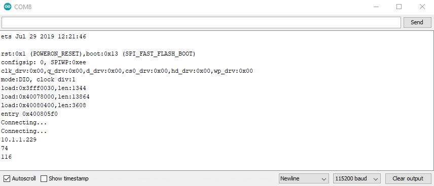
Test with
screen /dev/ttyUSB0 115200
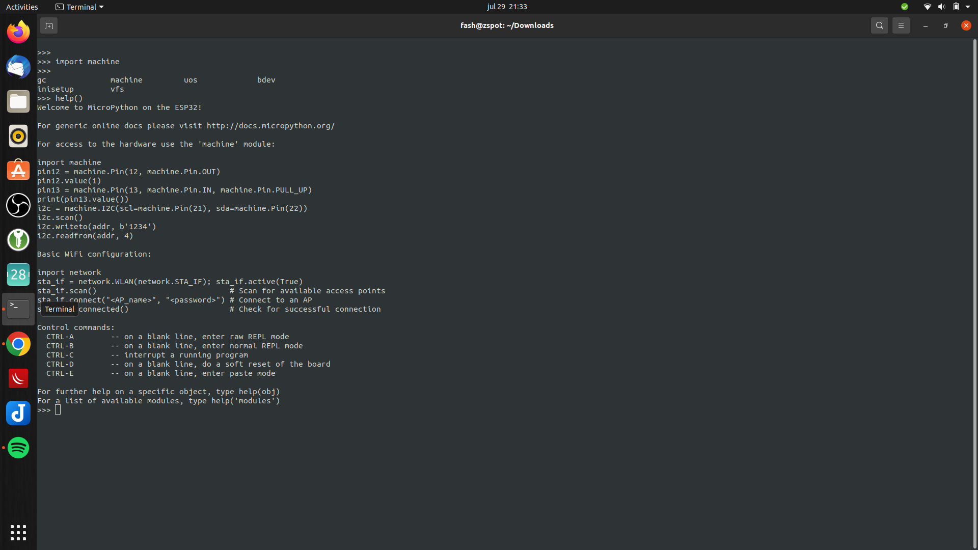
Enter
import machine
or
help()
Now we have to install a boot loader
Use ampy to list files
#list boot
ampy -p /dev/ttyUSB0 ls
/boot.py

#get boot.py
ampy -p /dev/ttyUSB0 get boot.py
vi boot.py (create new)
#import esp
#esp.osdebug(None)
#import webrepl
#webrepl.start()

def connect():
    import network
    sta_if = network.WLAN(network.STA_IF)
    if not sta_if.isconnected():
        print('connecting to network...')
        sta_if.active(True)
        sta_if.connect('WIFISSID', 'WIFIPASS')
        while not sta_if.isconnected():
            pass
    print('network config:', sta_if.ifconfig())
Push the file
ampy -p /dev/ttyUSB0 put boot.py
Usage: ampy [OPTIONS] COMMAND [ARGS]...

  ampy - Adafruit MicroPython Tool

  Ampy is a tool to control MicroPython boards over a serial connection.
  Using ampy you can manipulate files on the board's internal filesystem and
  even run scripts.

Options:
  -p, --port PORT    Name of serial port for connected board.  Can optionally
                     specify with AMPY_PORT environment variable.  [required]
  -b, --baud BAUD    Baud rate for the serial connection (default 115200).
                     Can optionally specify with AMPY_BAUD environment
                     variable.
  -d, --delay DELAY  Delay in seconds before entering RAW MODE (default 0).
                     Can optionally specify with AMPY_DELAY environment
                     variable.
  --version          Show the version and exit.
  --help             Show this message and exit.

Commands:
  get    Retrieve a file from the board.
  ls     List contents of a directory on the board.
  mkdir  Create a directory on the board.
  put    Put a file or folder and its contents on the board.
  reset  Perform soft reset/reboot of the board.
  rm     Remove a file from the board.
  rmdir  Forcefully remove a folder and all its children from the board.
  run    Run a script and print its output.
Connect to serial console using screen
sudo screen /dev/ttyUSB0 115200
(use CTRL-A \ to exit)
Connect to wifi
import boot
connect()
Led blinky test, with below file named ledtest.py
import time
from machine import Pin
led=Pin(2,Pin.OUT)        #Internal led pin

while True:
  led.value(1)            #Set led turn on
  time.sleep(0.5)
  led.value(0)            #Set led turn off
  time.sleep(0.5)
Upload and run script
ampy -p /dev/ttyUSB0 put ledtest.py
import ledtest (without .py!)
Next todo: boot.py @boot ?!?
Run custom python after booting.
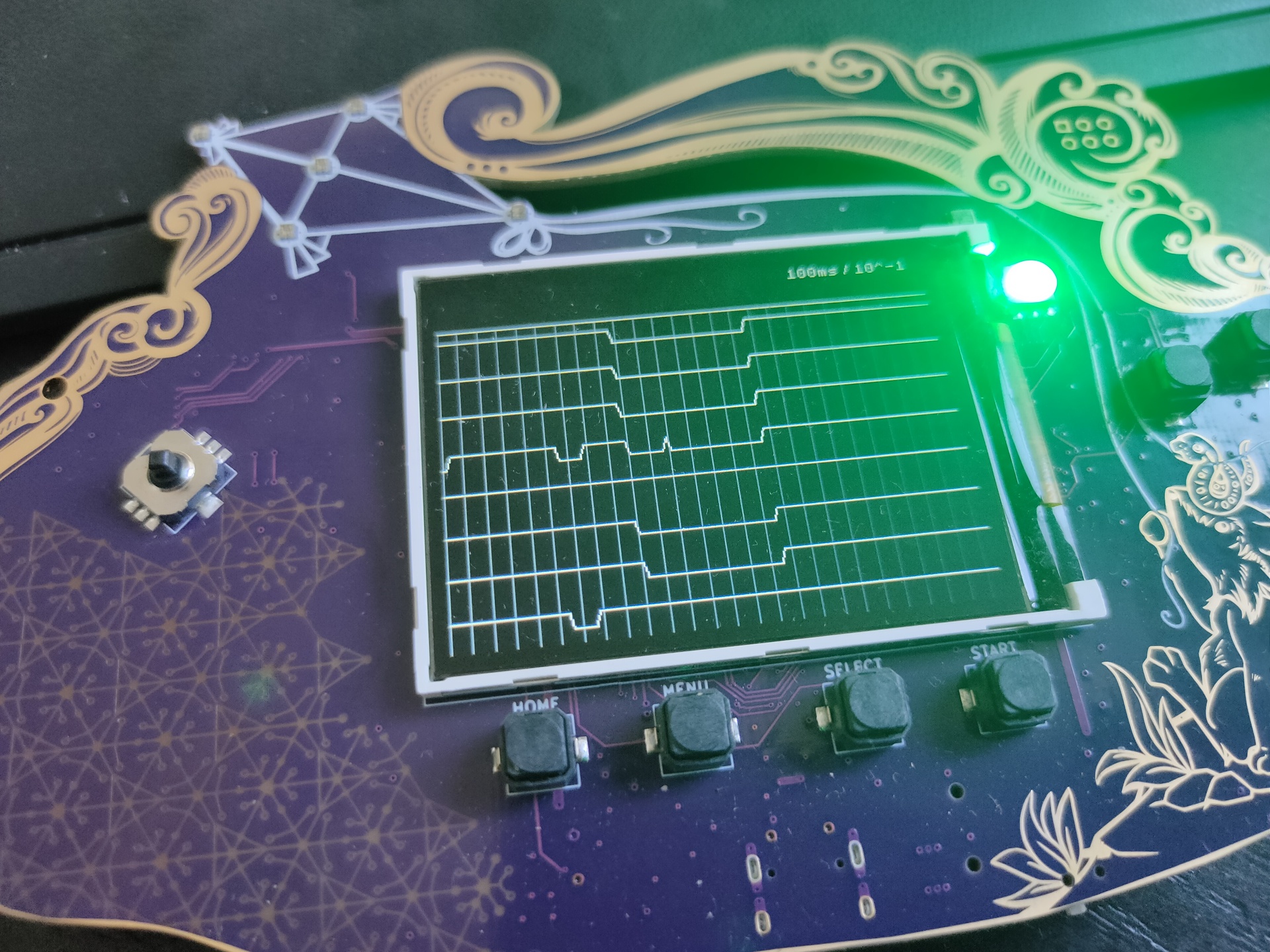
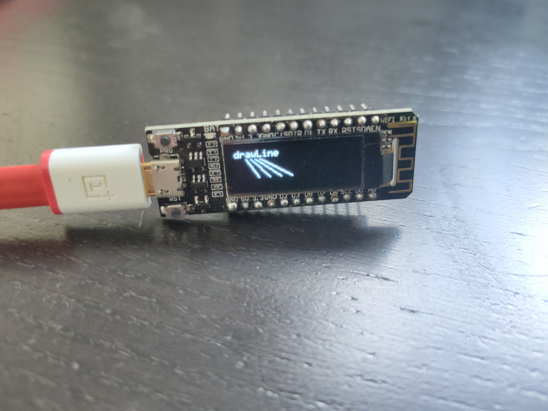
Connect display and play with drawing.
Tip: Install rshell !
sudo pip3 install rshell
fash@zspot:~$ rshell
Welcome to rshell. Use Control-D (or the exit command) to exit rshell.

No MicroPython boards connected - use the connect command to add one

/home/fash> autoconnect: /dev/ttyUSB0 action: add

/home/fash> ?

Documented commands (type help <topic>):
========================================
args    cat  connect  date  edit  filesize  help  mkdir  rm     shell
boards  cd   cp       echo  exit  filetype  ls    repl   rsync

Use Control-D (or the exit command) to exit rshell.
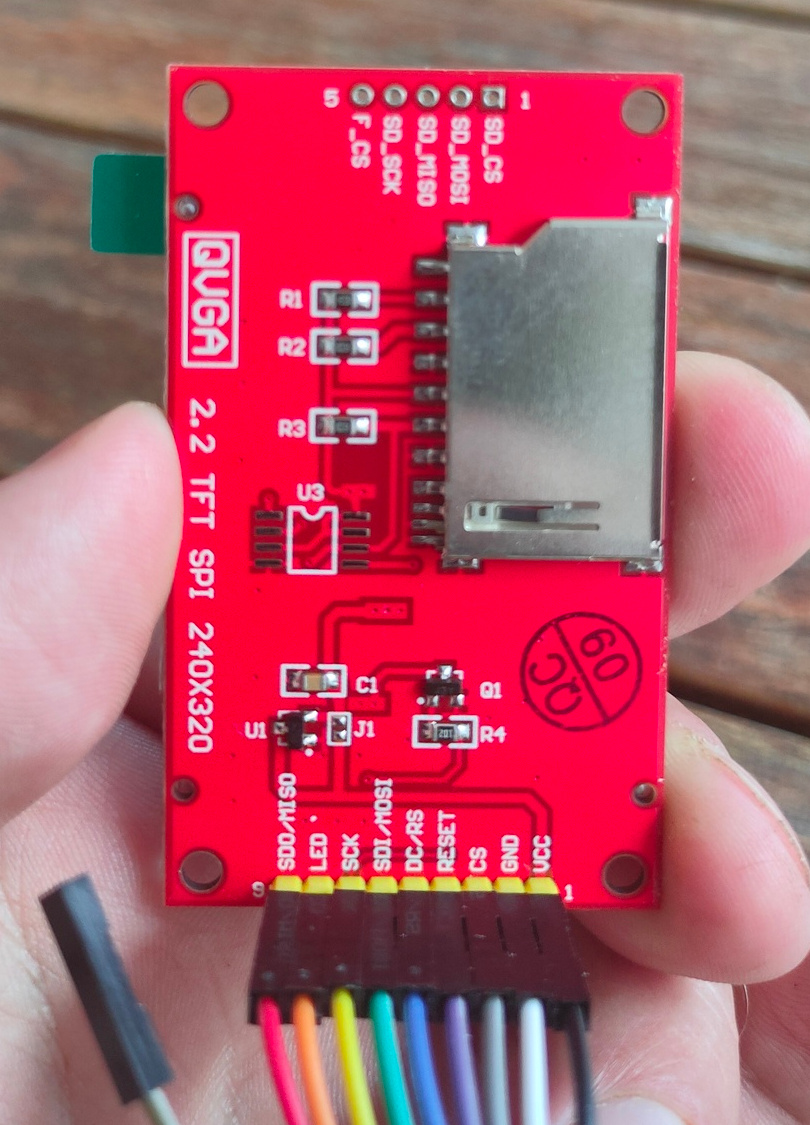
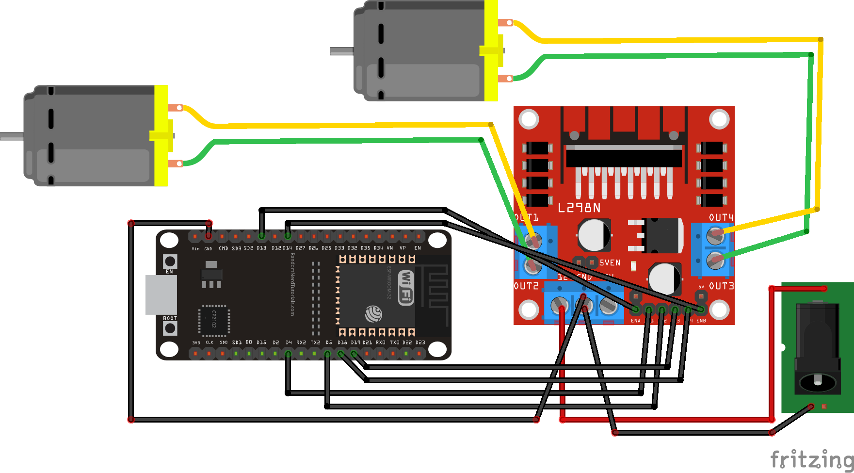
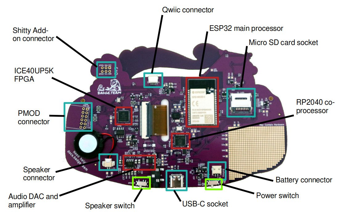
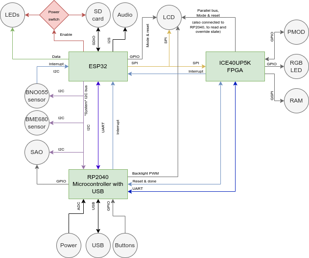
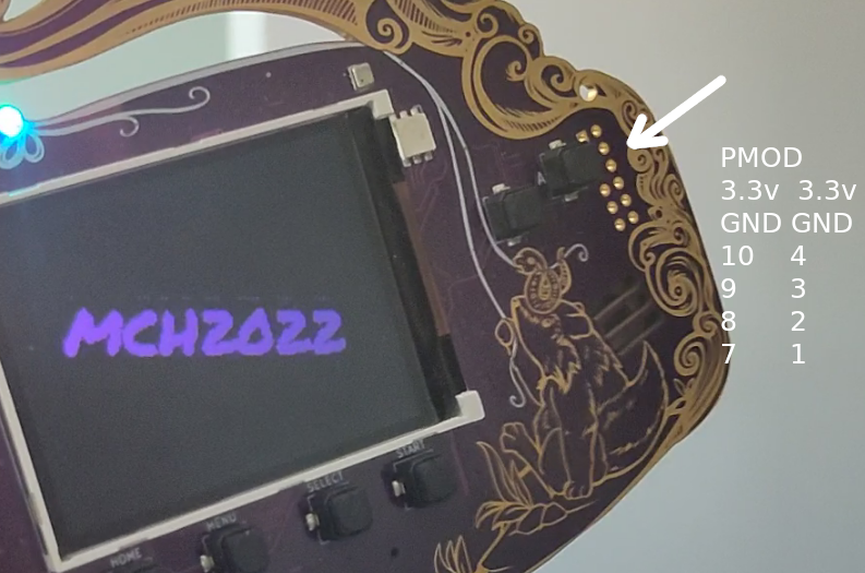
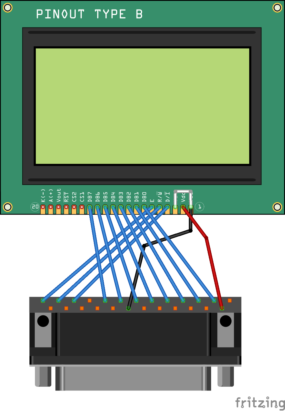
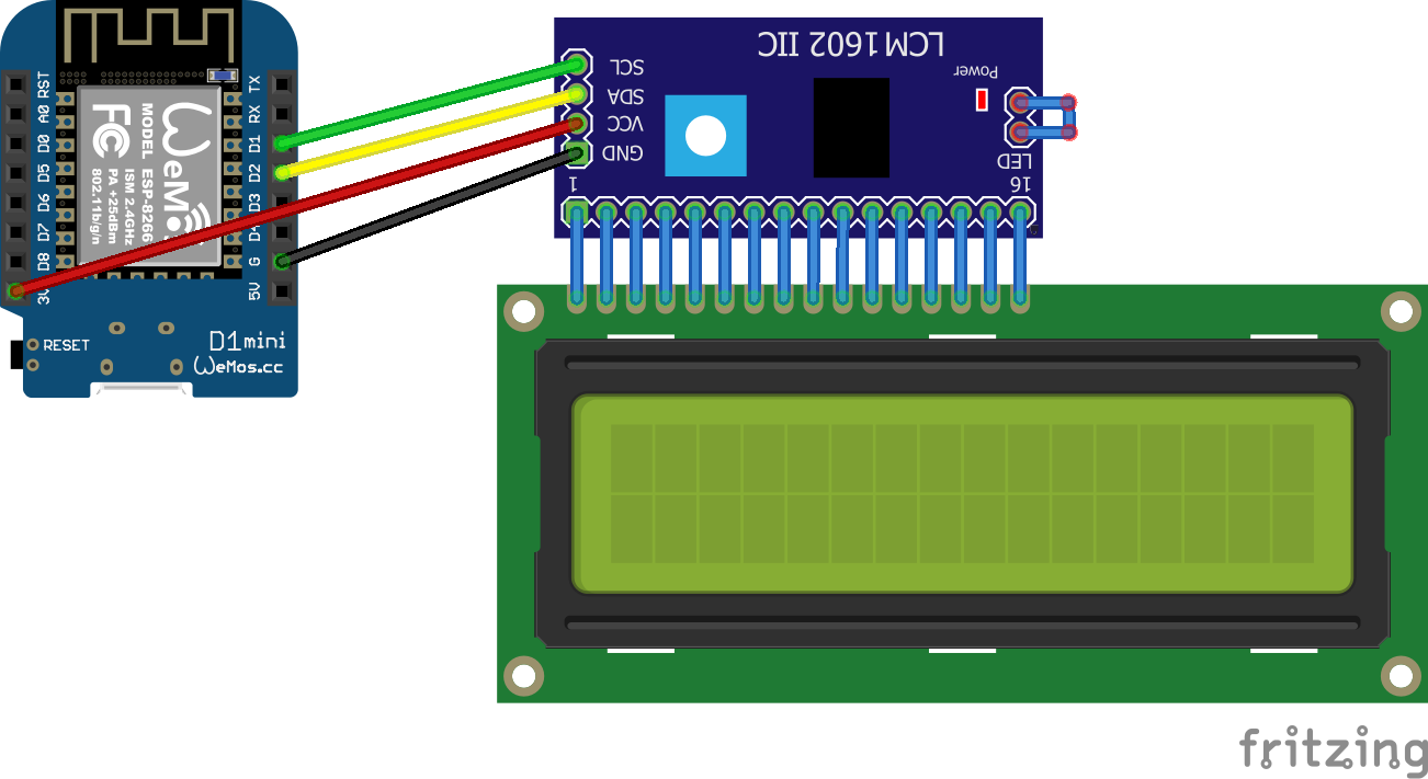
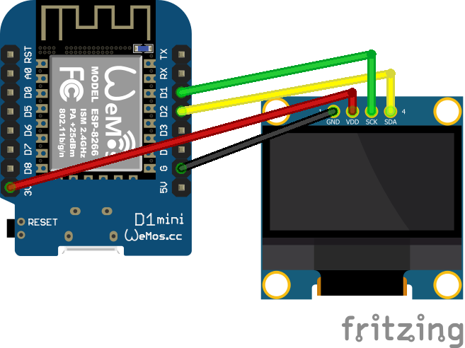
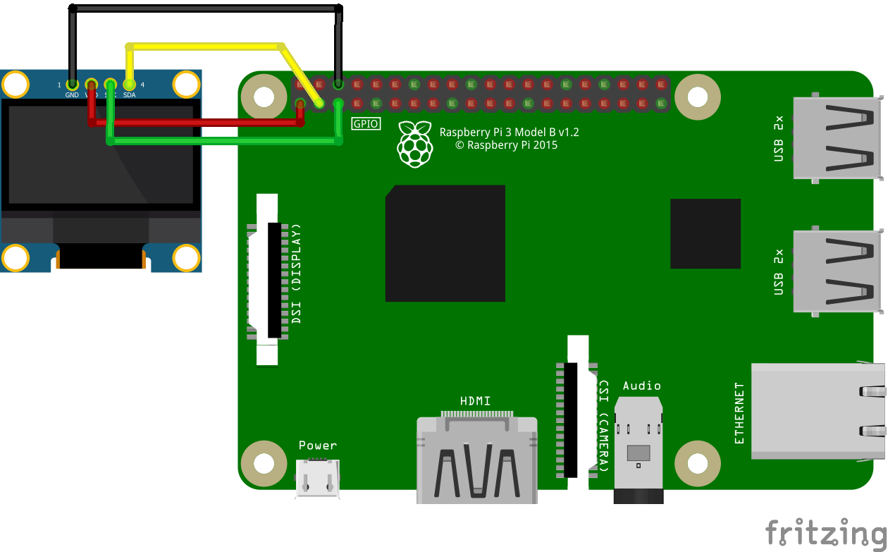
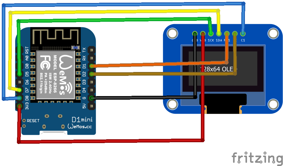
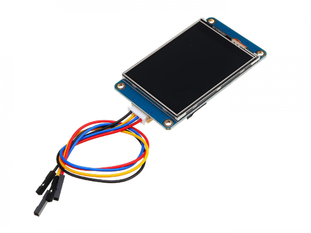
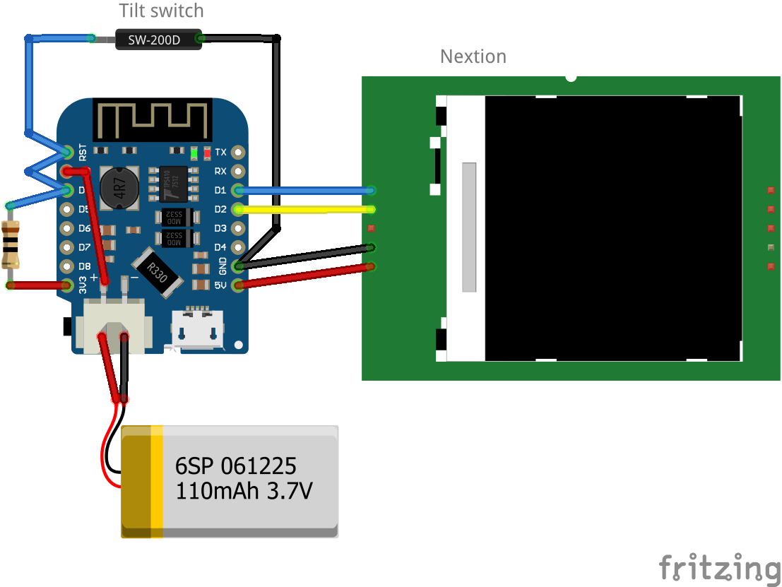
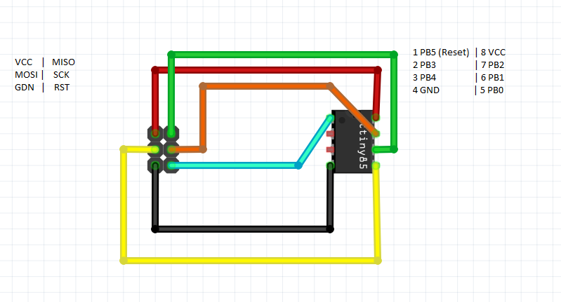
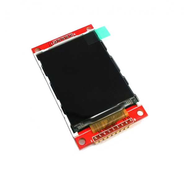
Connecting the display
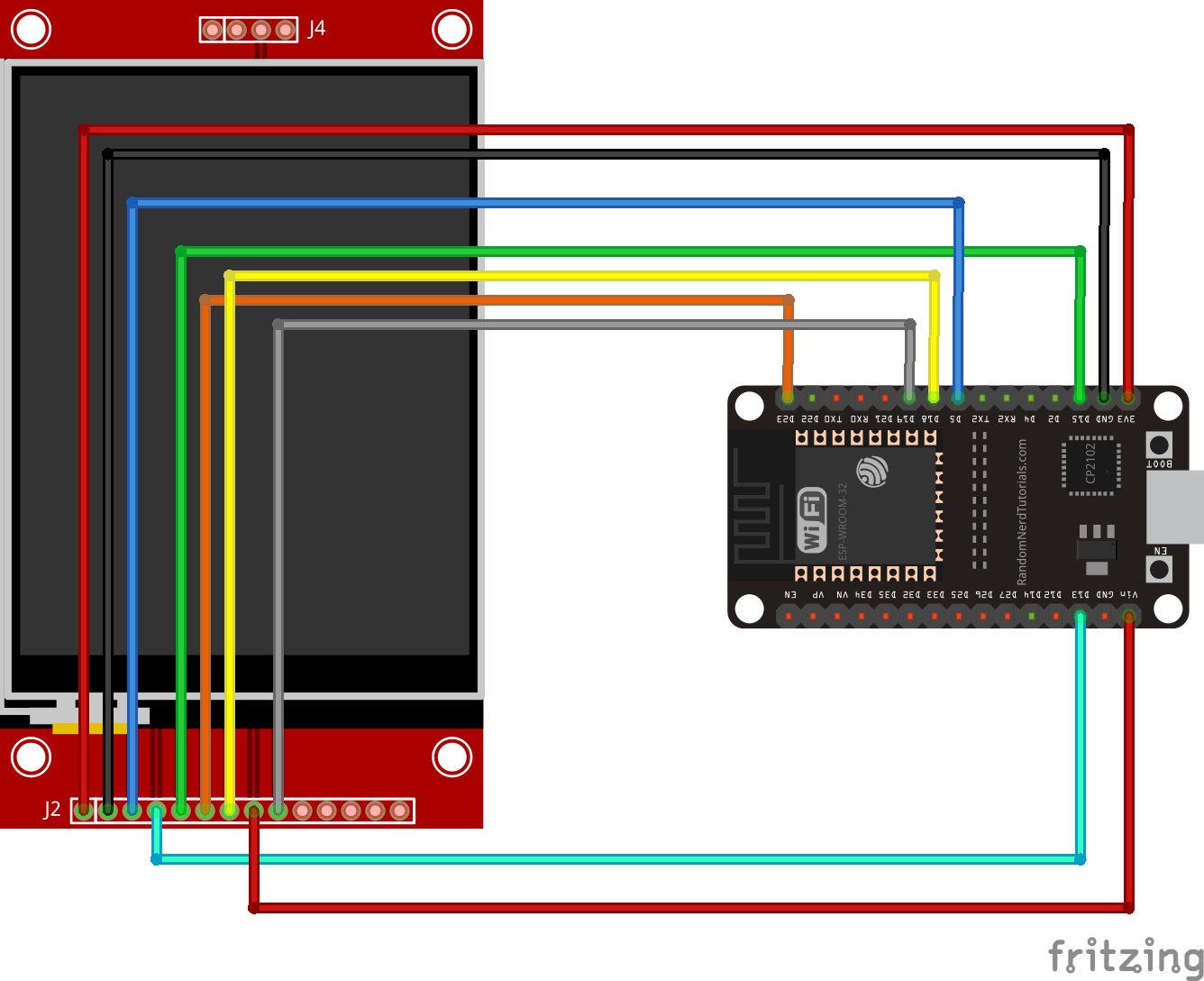
I’ve connected the display as above. Note the different connections on the display. Above fritzing part has connections for touch screen!
The 4 or 5 pins on the other side are for sdcard functionallity.
display       esp
-----------------
SDO/MISO      D19
LED           VIN (5v)
SCK           D18
SDI/MOSI      D23
DC/RS         D15
RESET         D14
CS            D5
GND           GND
VCC           3.3V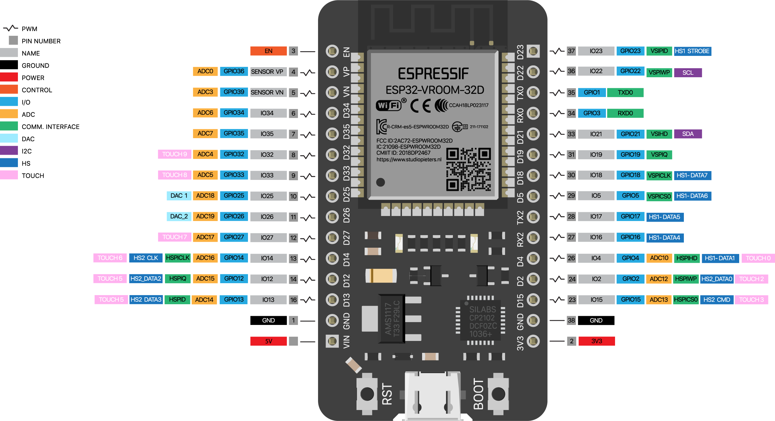
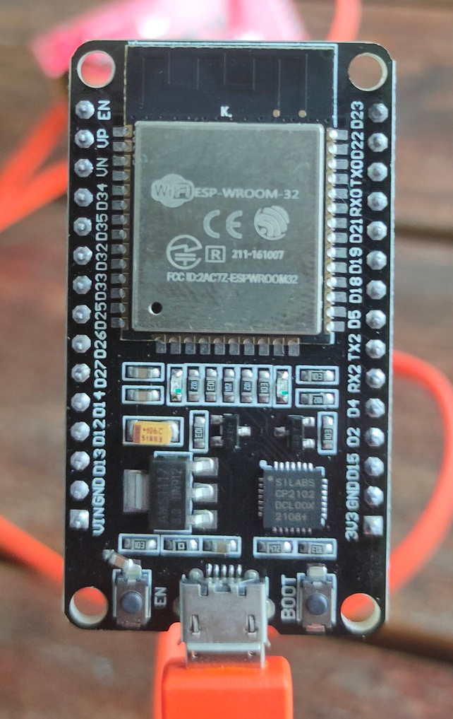
Not my different ESP, gpio has high numbers and only 30 pins.
Most ESP have 2 SPI controllers. Check yours!
Software part
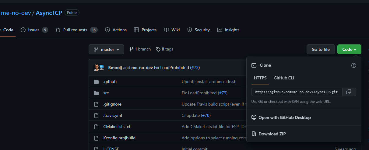
git clone https://github.com/rdagger/micropython-ili9341
Next create a setupmydisplay.py file, and edit your pin connections
from ili9341 import Display
from machine import Pin, SPI

TFT_CLK_PIN = const(18)
TFT_MOSI_PIN = const(23)
TFT_MISO_PIN = const(19)

TFT_CS_PIN = const(5)
TFT_RST_PIN = const(14)
TFT_DC_PIN = const(15)

def createMyDisplay():
    #spi = SPI(0, baudrate=40000000, sck=Pin(TFT_CLK_PIN), mosi=Pin(TFT_MOSI_PIN))
    spiTFT = SPI(2, baudrate=51200000,
                 sck=Pin(TFT_CLK_PIN), mosi=Pin(TFT_MOSI_PIN))
    display = Display(spiTFT,
                      dc=Pin(TFT_DC_PIN), cs=Pin(TFT_CS_PIN), rst=Pin(TFT_RST_PIN))
    return display
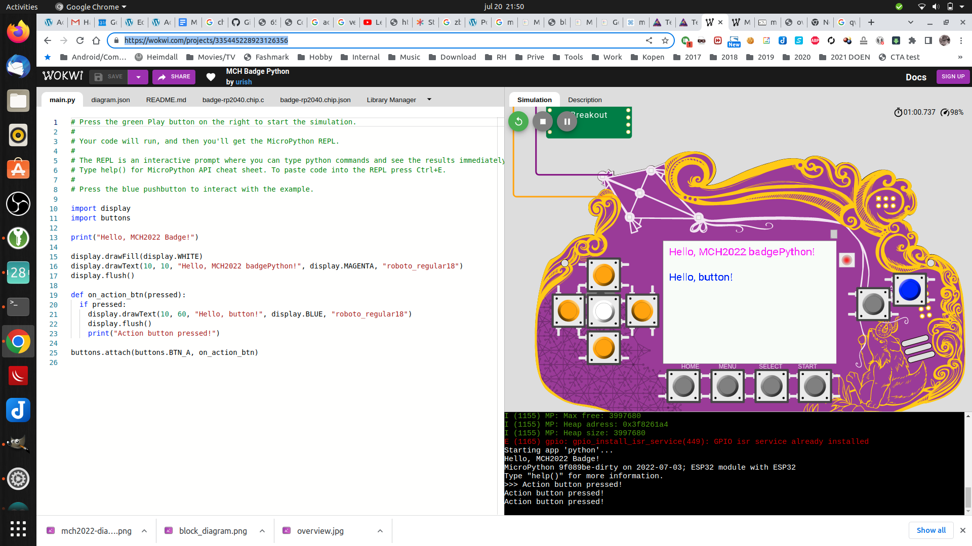
Now you can use the library by editing a example like demo_bouncing_boxes.py
Add and change
# At the beginning of the file
import setupmydisplay.py

Futher down comment two lines and add your own setup

        # Baud rate of 40000000 seems about the max
        #spi = SPI(1, baudrate=40000000, sck=Pin(14), mosi=Pin(13))
        #display = Display(spi, dc=Pin(4), cs=Pin(16), rst=Pin(17))
        display = setup.createMyDisplay()
Upload to ESP32 and testing!
ampy -p /dev/ttyUSB0 put demo_bouncing_boxes.py
ampy -p /dev/ttyUSB0 put setupmydisplay.py
# connect and start
sudo screen /dev/ttyUSB0 115200
import demo_bouncing_boxes.py