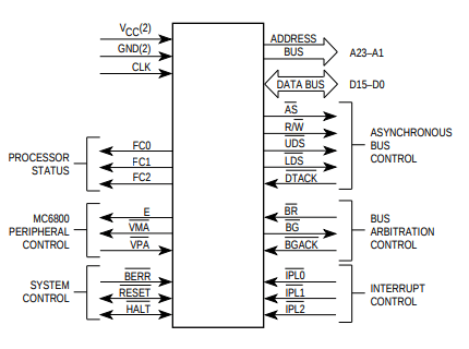
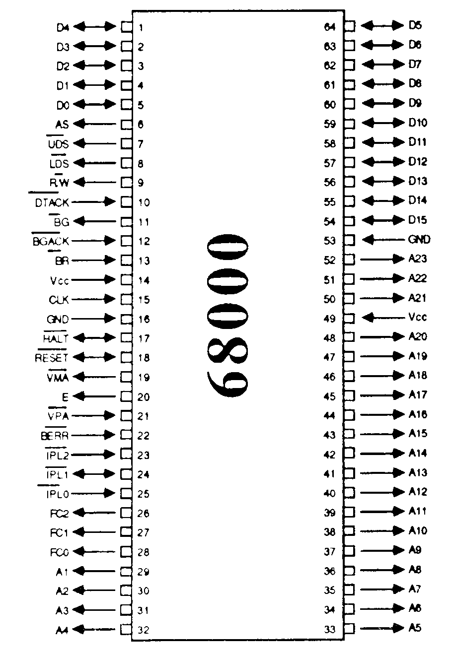
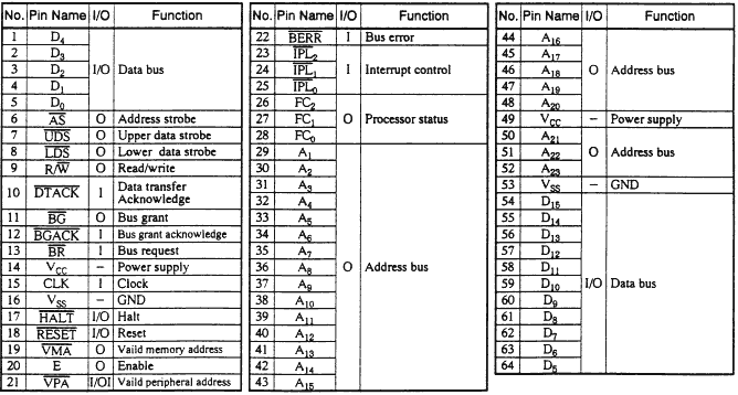
PROCESSOR FUNCTION CODES (FC0, FC1, FC2) These function code outputs indicate the mode (user or supervisor) and the address space type currently being accessed.
The following table shows the
meaning of these three bits.
FC2 FC1 FC0 Meaning
0 0 0 Not used
0 0 1 User data
0 1 0 User program
0 1 1 Not used
1 0 0 Not used
1 0 1 Supervisor data
1 1 0 Supervisor program
1 1 1 Interrupt Acknowledge
These outputs can therefore inform external circuitry what is happening
inside the 68000. They could, for example, be used to switch in differentbanks of memory.
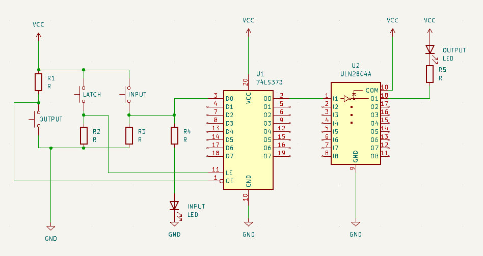
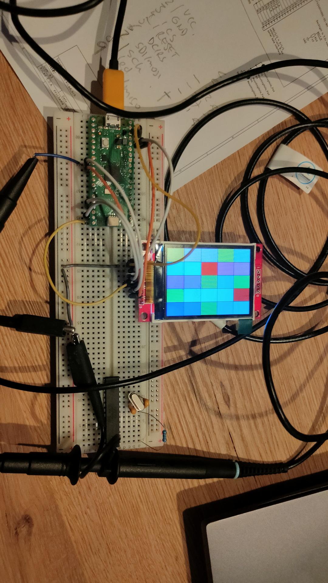
Using a small 8266 with a display, I wanted to see if it’s useful to monitor this information.
So using a trick with the uln2804/uln2803 as level convertor (don’t connect the VCC, and the output will drop to a level that is around the 3.3v. (I was out of bi-directional level convertors)
Latch demo
I’ve been using latches in the past, but I wanted to show how it works using a little demo setup. Below movie is for the Bus Controller I posted recently.
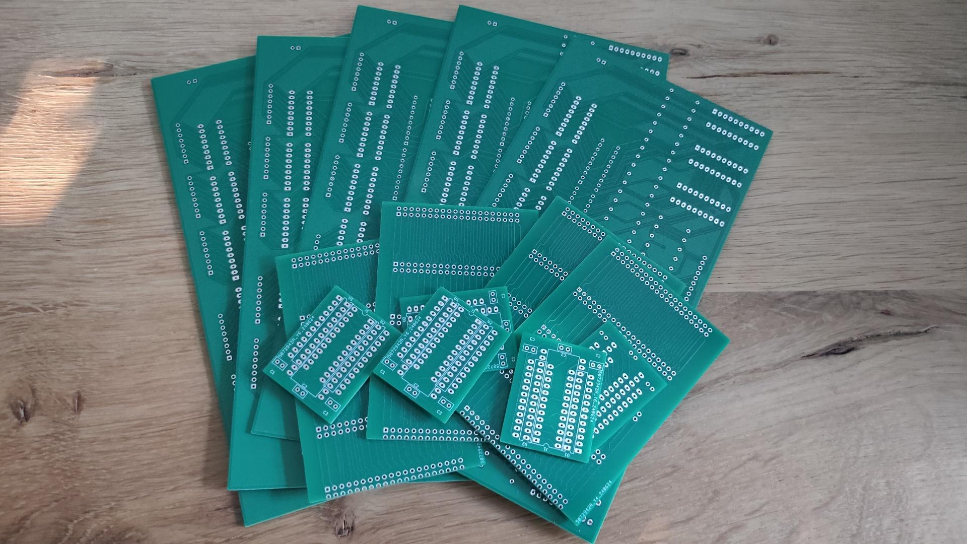
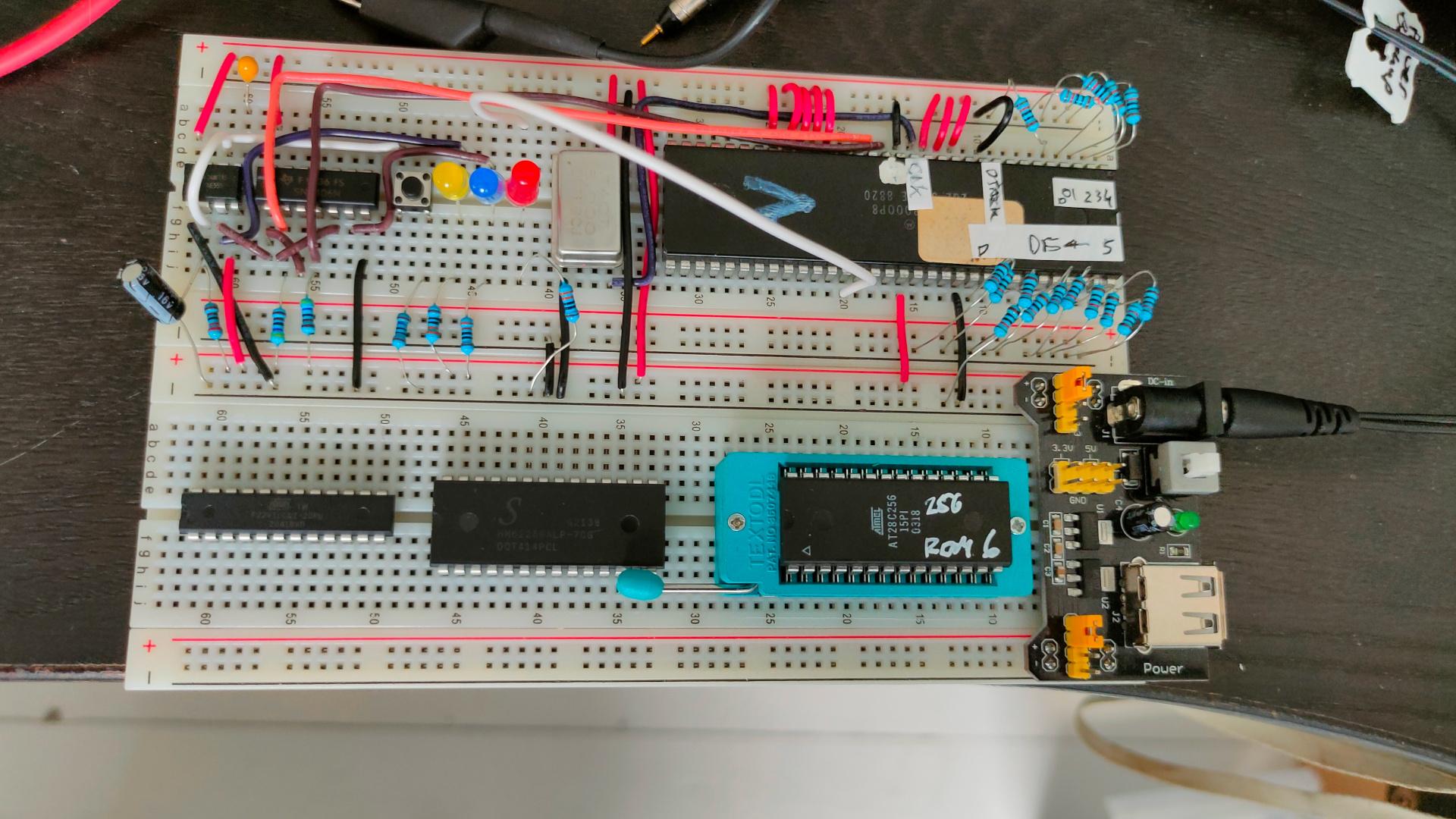
While busy fixing my business site, and working for a customer, I build a testing rig for the 68000.
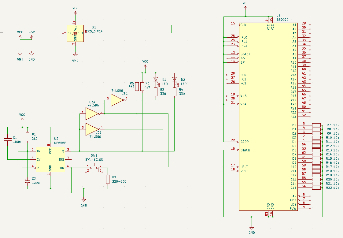
I first made a power-on reset schematic. The timing is different from the 6502 power-on reset, and the 68k needs HALT and RESET being pulled low.
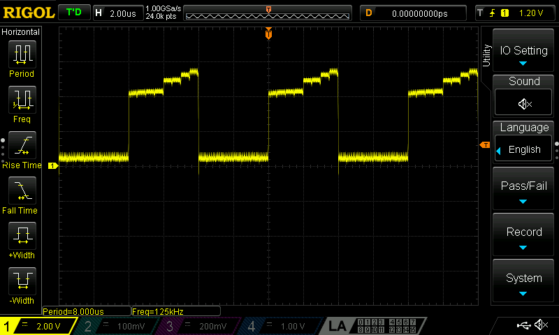
Inverted reset signal (before the 74ls06 invertor)
Pulse from A17
Schematic with poweron reset, some leds and 8mhz crystal Lines pulled to GND or VCC are at least needed to get a running CPU. Data bus resistors are needed because data is r/w
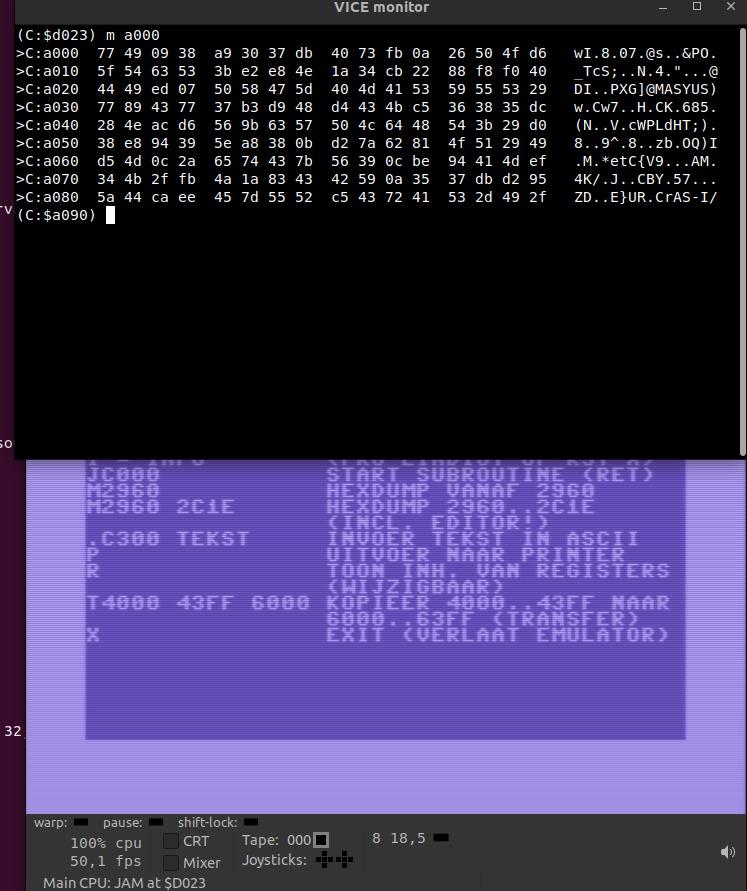
All Data lines are pulled low, emulating opcode 00 00 https://68k.hax.com/ORI%20to%20CCR This will do nothing weird, and will increment the address and try to read the next opcode. Resulting in an endless incrementing address bus, I’ve put a Led (Red)on Address A17.
I bought a little notebook while being there. I wrote about 12 pages of ideas, schematics and projects to start.
Rewrite Wozmon to use my composite pcb (Atmega328) access though via
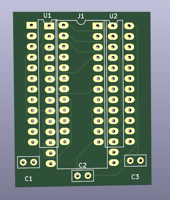
Building a 68000 pcb with a minimal machine code monitor. Using a atf22v10 as address decoder. (Same as my 6502 , I love those devices) Maybe I’ll add a micro sdcard reader
Add a lcd matrix display to my 8088/8086
Creating a PLA alternative for C64 using ath22v10 (again)
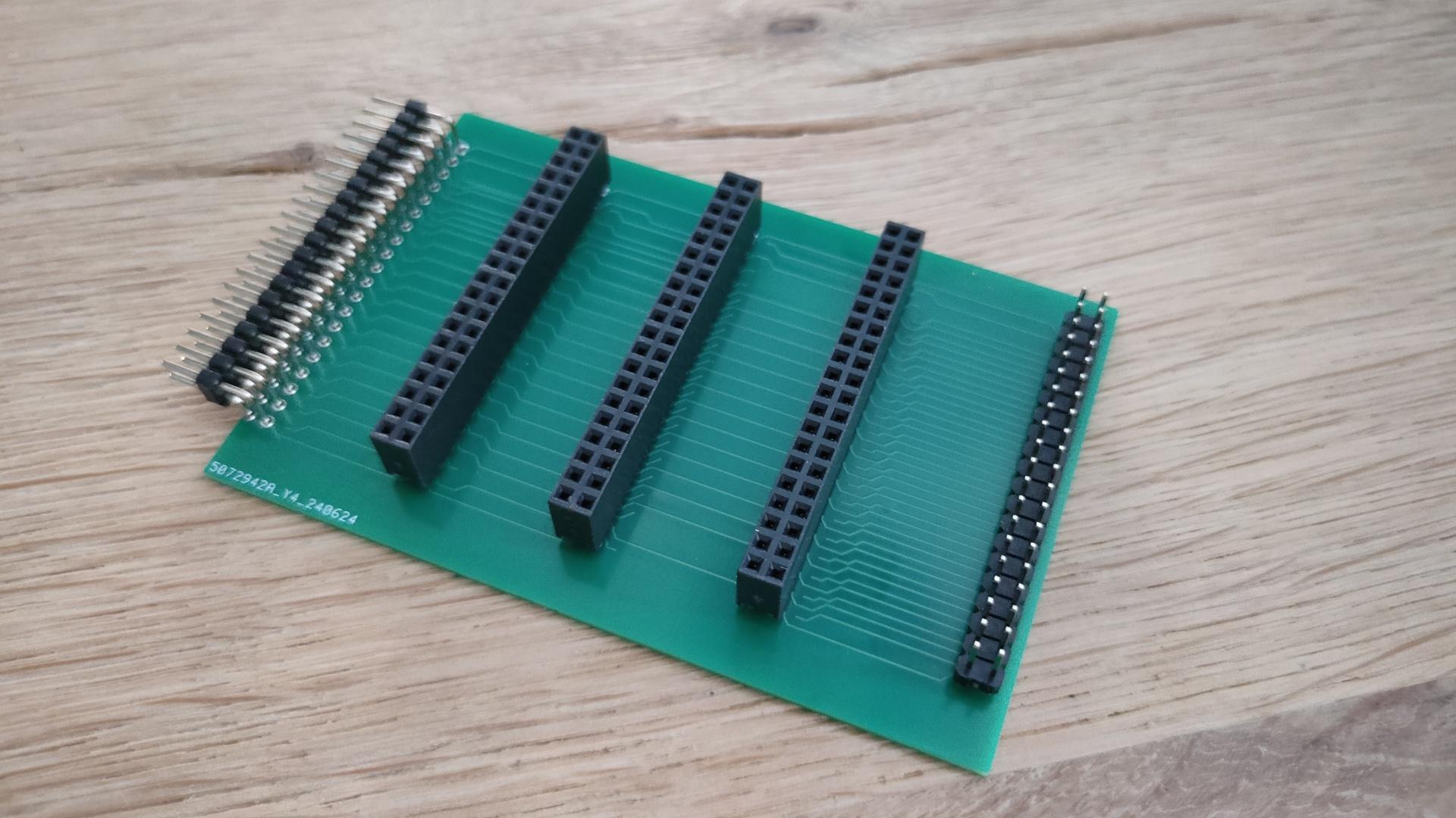
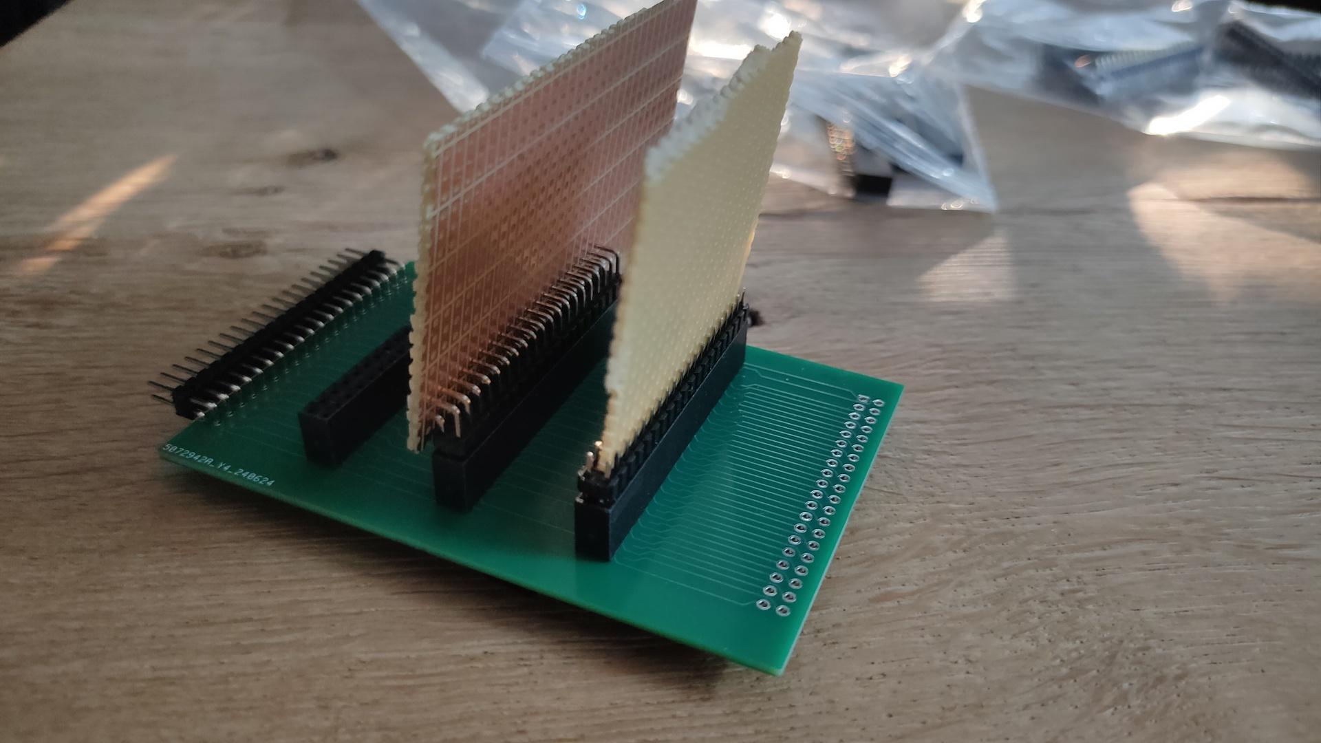
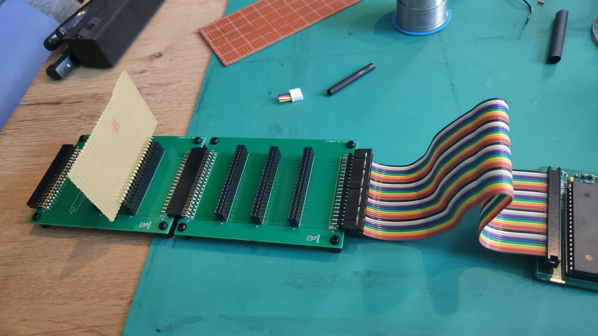
Make backplanes for my 6502, so I can plug cards with different POC cards. Clockcard, Latched bus leds, multiple VIA’s, IRQ controller, SID + Buzzer (Maybe also AY-3-8910, see other posts), LCD, composite, serial, Matrix and serial_usb) keyboard)
IRQ controller because I have some devices without opendrain, so I can’t tie all IRQ’s together
Amiga Chip Mem mod for rev 5 (using a ‘new’ 8372A)
8085 Cartridge new approach
C64Pico fix and add backplane + breadboard version for POCs
… more
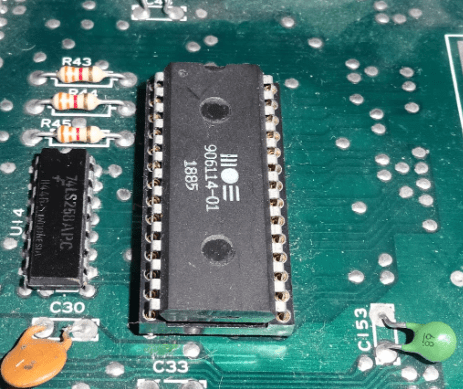
First version PLA with atf22v10
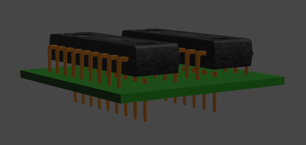
PCB mockup (two ATF22v10 on top and a wide pin setup for placement in C64
Wide PLA
8085 Cartridge revisited
Working on 8085 cartridge
Problem with cartridge: prg is 17k, exomized 10k. So you need 2 banks of 8k. This disables basic rom, needed for the program. The program needs to be relocated to 0x800 anyway. So my exomizer options will take care of that. But the basic is not being enabled again.
exomizer sfx sys -o data.exo -Di_ram_enter=\$37 -Di_ram_during=\$34 -f'LDA #$37 STA $01' 8085.prg
xa frame.asm -o frame.bin
x64 -cart16 frame.bin
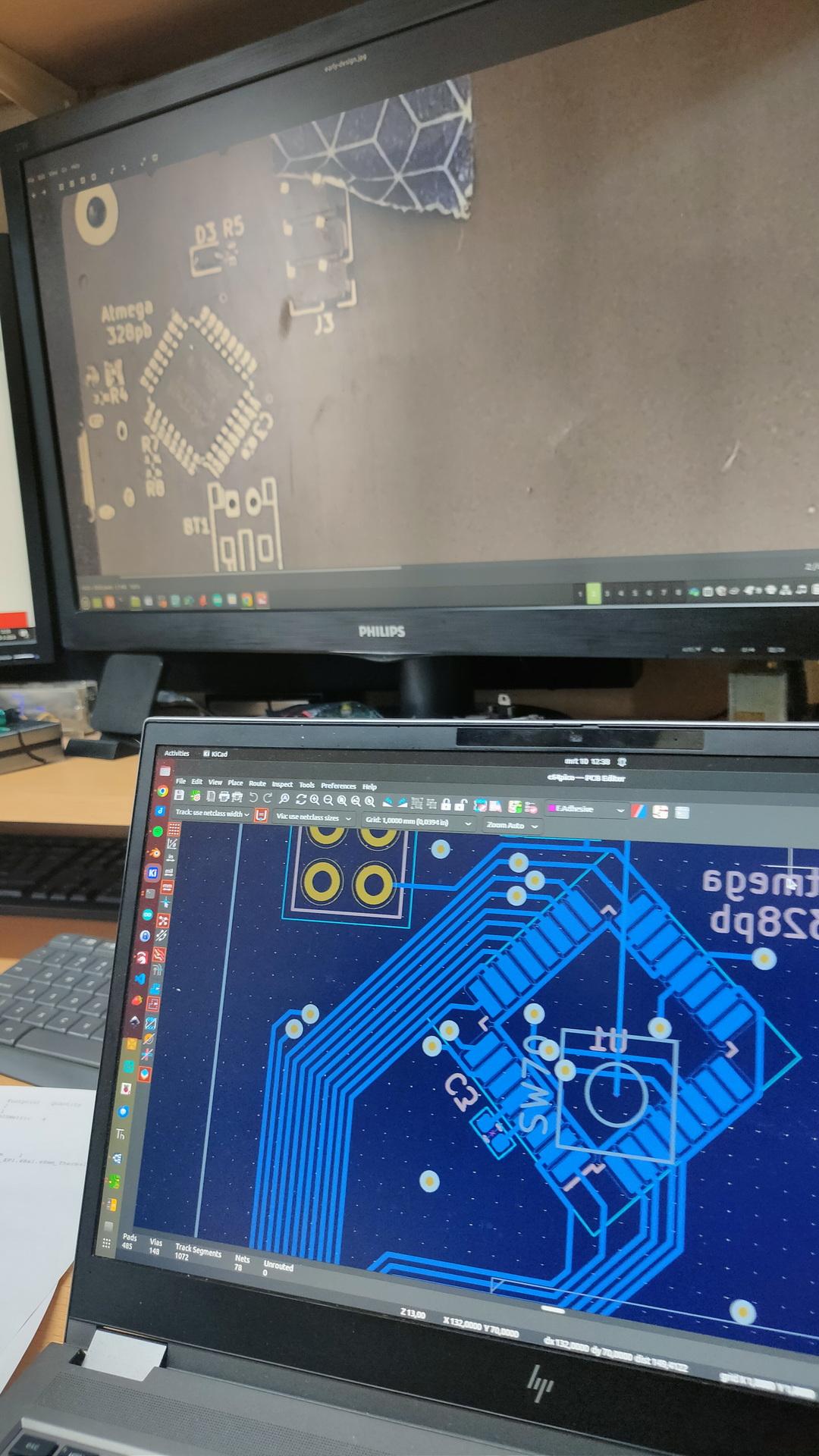
Today we worked on this project again. (Bigred and me)
There were some problems we needed to fix since last time:
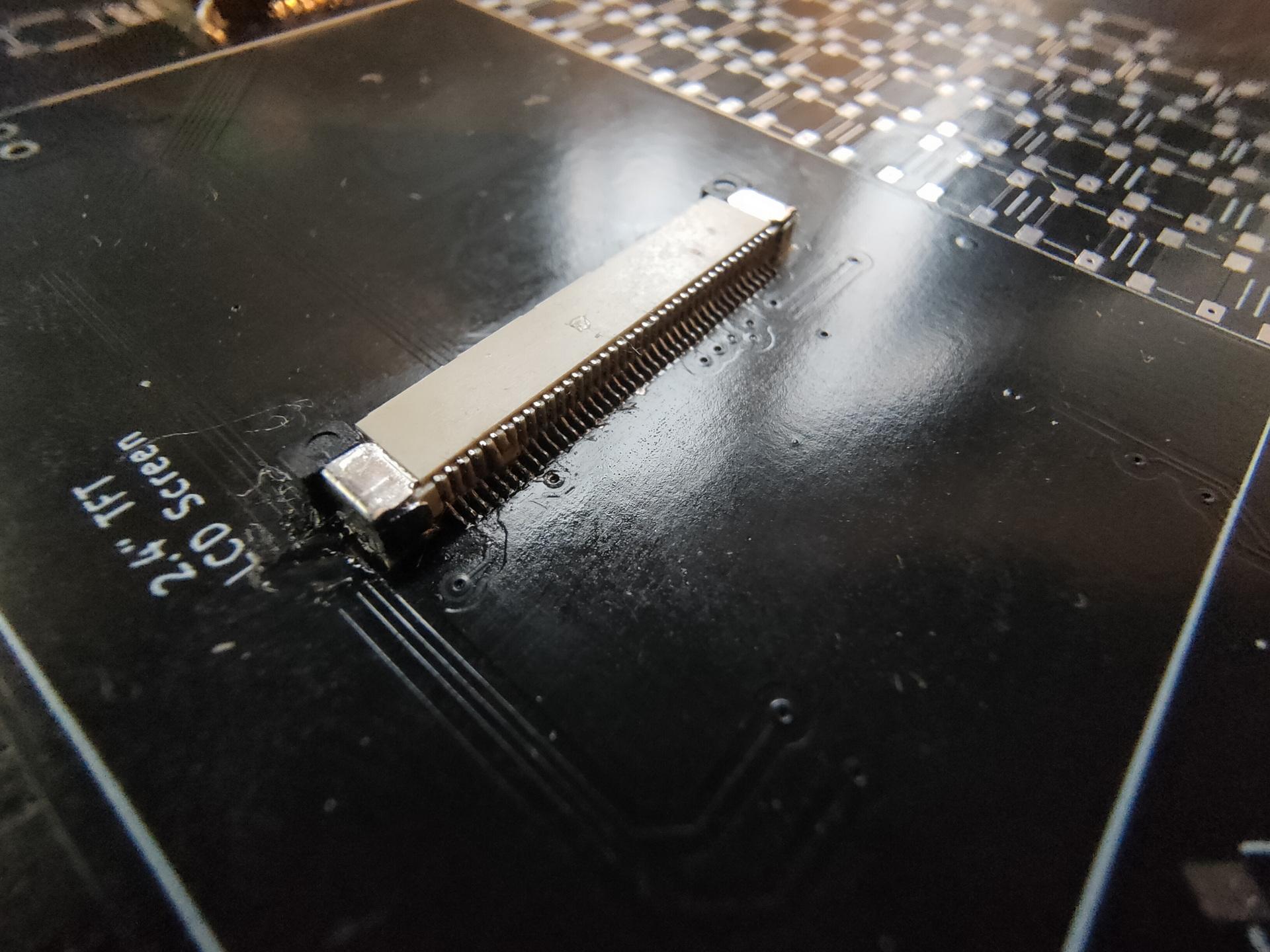
It was quite hard to get the correct parts. Our display connector was only fitted with connection pins on the wrong side of the connector. (up/down) So I bought a connector with both positions populated. So we had to replace this hard to solder (40 pin) connector.
It was not clear what the orientation should be of the atmega328pb. We looked at the pinout, and followed the VCC/GND. But these are also available of the opposite side of the chip. (We missed that) Later, we saw a tiny line on the PCB, which showed the pin 1 placement. So we had to remove and replace the chip. When turning on the power, (with incorrect placement) probably fried R5 (10k resistor), on both our boards. Had to replace those also.
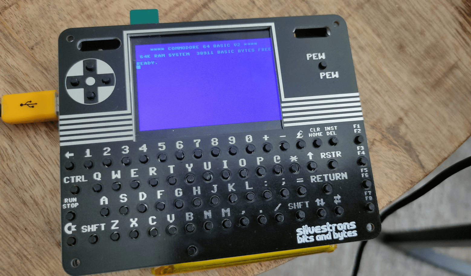
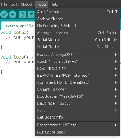
Programming the atmega328pb was not easy, see below fixes.
Compiling the pico firmware resulted in a black screen. Below the fixes I had to make to get the screen working.
Other things still to fix.
Bigreds screen.
atmega328p didn’t work for Bigred, so probably needs to replace with the pb version.
My battery controller is not charging. See bottom of page
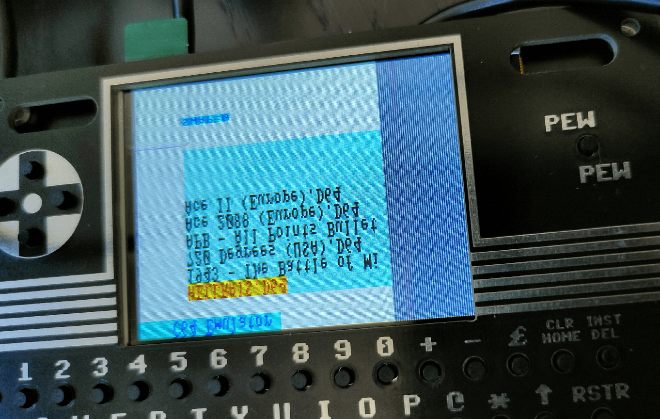
Some of my buttons are working. The pewpew and some of the cursor keys (not as I expect, there are some up/down issues) And none of the other keys are working.
Some other things we noticed.
sdcard: remove partitions, format using mkfs.exfat Create a c64 directory on this filesystem where you can put the d64 files!
0402 SMD is far too small for me. There is enough room on the board to use 0805 for example. Even THT is possible, there are only a few components.
Some components are TOO close together, removing a component resulted in other small parts disconnecting also.
My friend Bigred said: If I can see it, I can solder it. But it is not easy. This probably keeps a lot of people from building it!
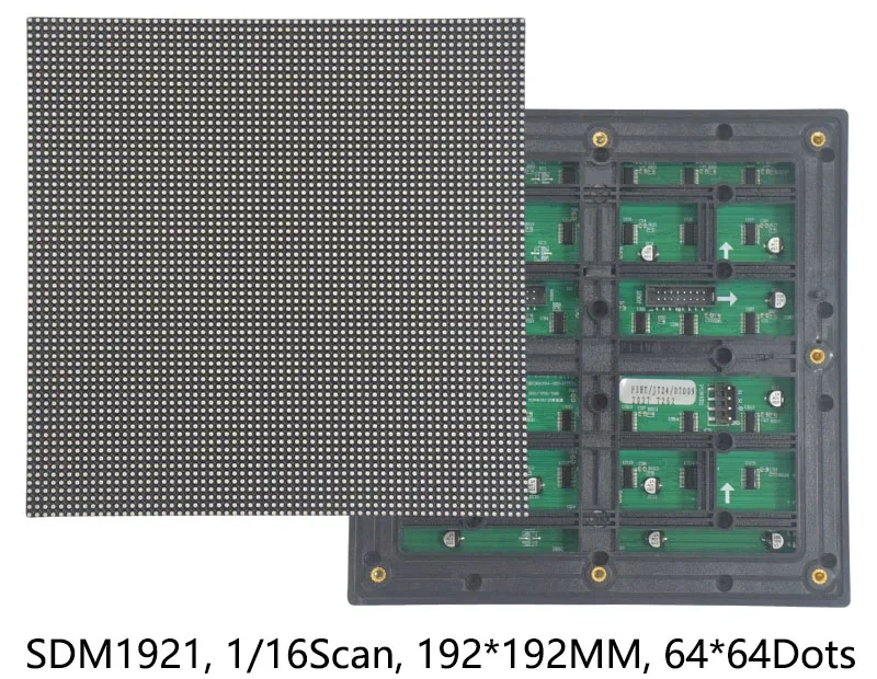
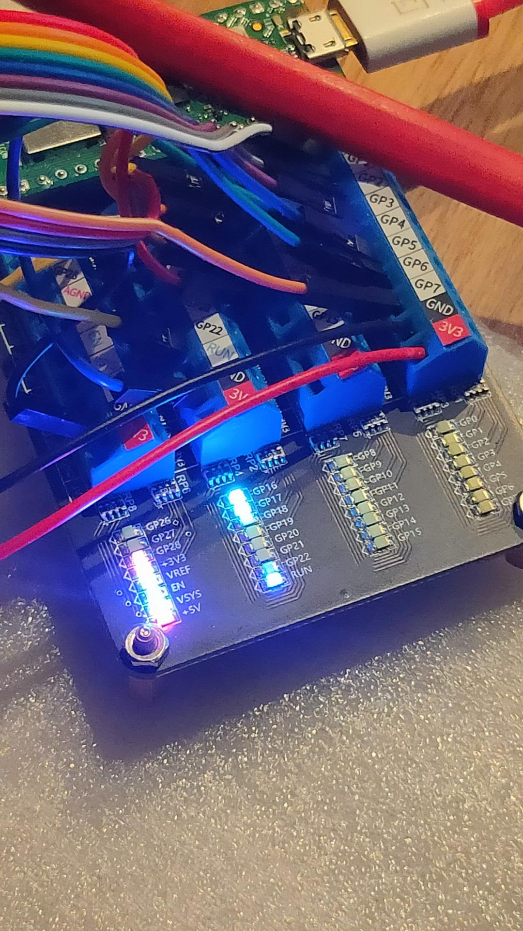
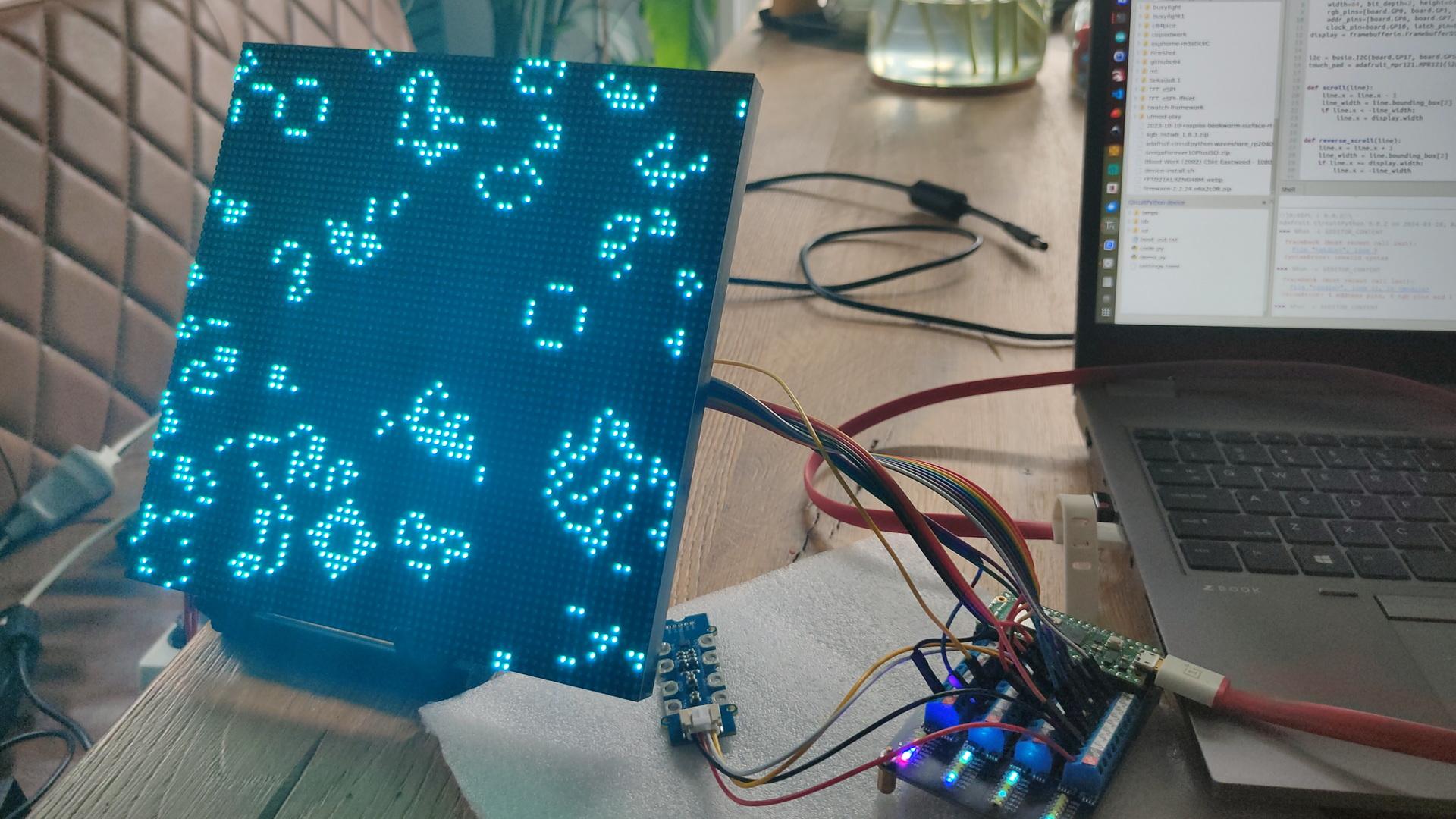
Yesterday I got this nice led matrix I mentioned before.
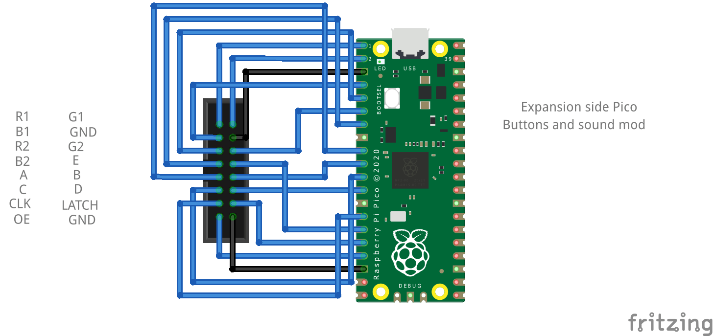
I wanted to control this display using Circuit Python and a Raspberry Pico.
Pico  Matrix
GP0   R1
GP1   G1
GP2   B1
GP3   R2
GP4   G2
GP5   B2
GP6   A
GP7   B
GP8   C
GP9   D
GP10  Clock
GP11  E
GP12  Latch
GP13  Output Enable

GND   GND ( I did both )
I installed Circuit Python and the following libraries.
adafruit_imageload, adafruit_display_text.label (the rest was already in the uf2 firmware.) (Check this link : https://circuitpython.org/board/raspberry_pi_pico/ ) I could not install the Wifi uf2 file, then I got a out of storage space when installing the adafruit libraries.
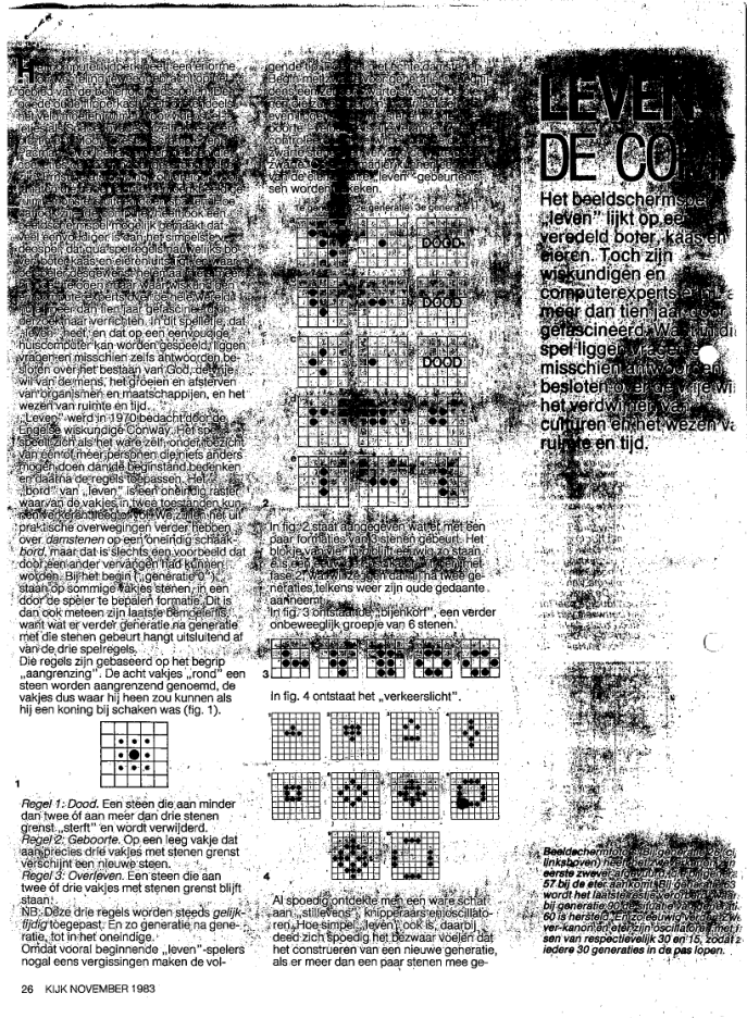
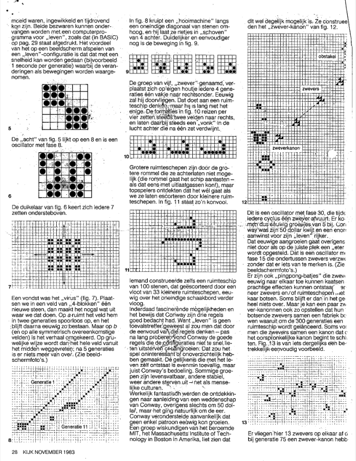
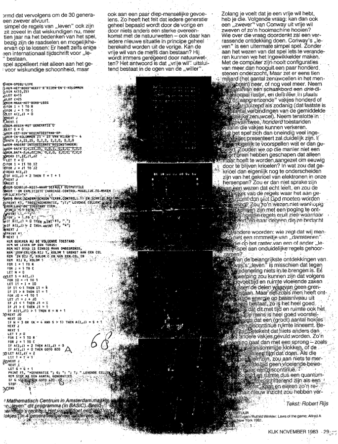
I became interested in Conway’s “Game of Life”, in 1983. Reading a article in the Dutch Magazine Kijk.
The Game of Life, also known simply as Life, is a cellular automaton devised by the British mathematician John Horton Conway in 1970. It is a zero-player game, meaning that its evolution is determined by its initial state, requiring no further input. One interacts with the Game of Life by creating an initial configuration and observing how it evolves. It is Turing complete and can simulate a universal constructor or any other Turing machine.
I found these on my server. Bad quality, I know. Scanned these many years ago.
The rules are:
Any live cell with fewer than two live neighbours dies, as if by underpopulation.
Any live cell with two or three live neighbours lives on to the next generation.
Any live cell with more than three live neighbours dies, as if by overpopulation.
Any dead cell with exactly three live neighbours becomes a live cell, as if by reproduction.
When playing with the Basic code as a kid, I wanted to try if it was possible to make a 3D version of this.
I came up with the following rules:
Birth : 4 alive neighbours needed
Survive : 5 or 6 neighbours
Dead : below 4 and over 6
I think there should be a BBC Acorn basic version I wrote somewhere.
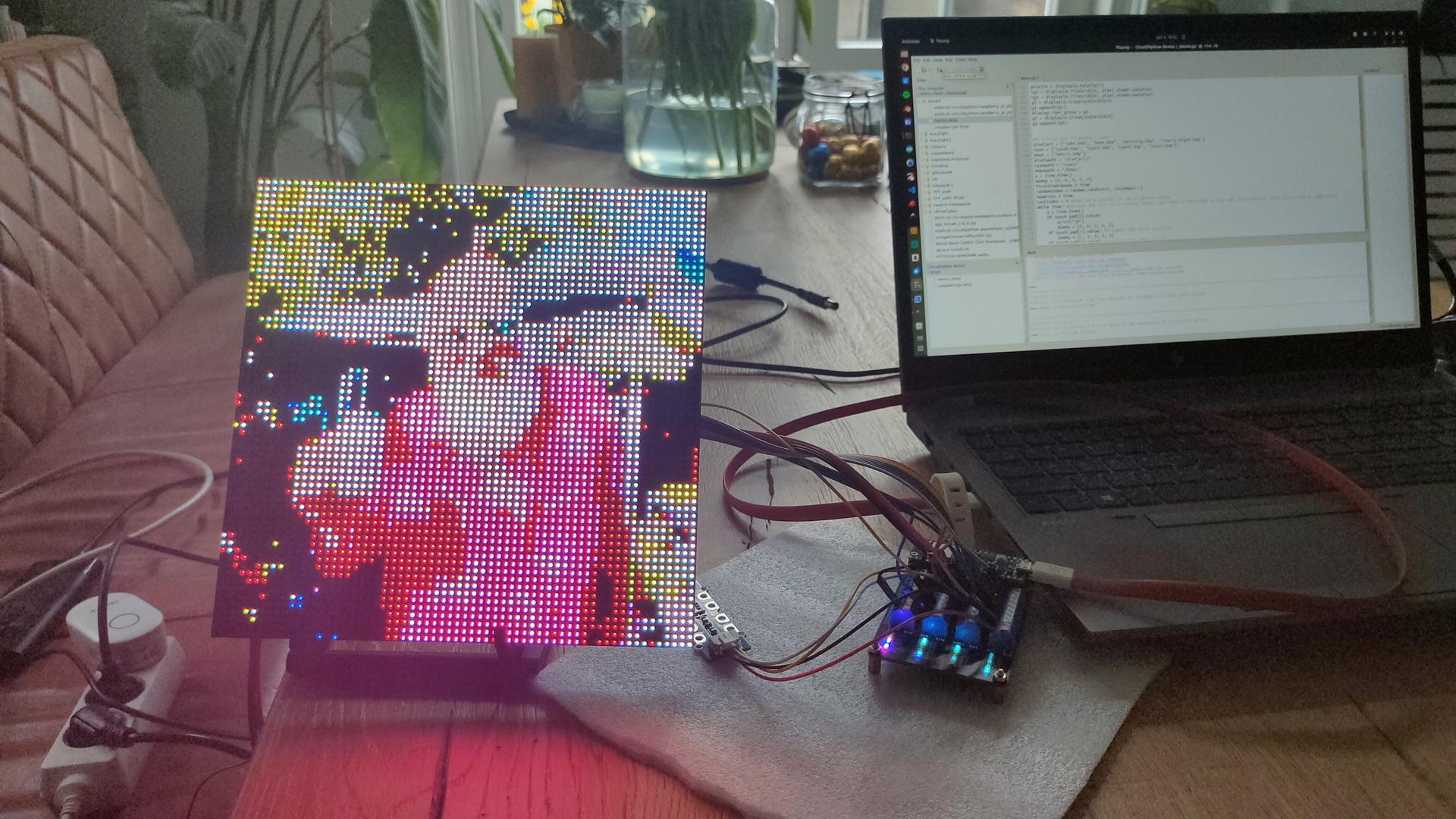
Back to the display
Pico BoardGame of LifeDisplaying a imageGreetings to my friendsGame of Life starting with my Logo plus a gliderA single Gosper‘s glider gun creating gliders
Code for the glider gun
    conway_data = [
        b'                        +           ',
        b'                      + +           ',
        b'            ++      ++            ++',
        b'           +   +    ++            ++',
        b'++        +     +   ++              ',
        b'++        +   + ++    + +           ',
        b'          +     +       +           ',
        b'           +   +                    ',
        b'            ++                      ',
    ]
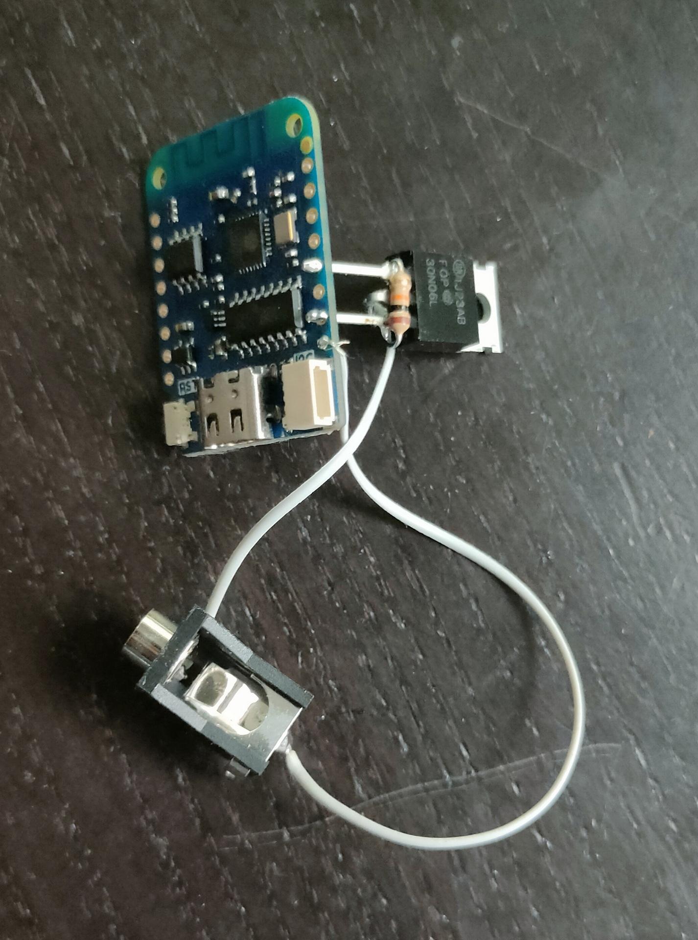
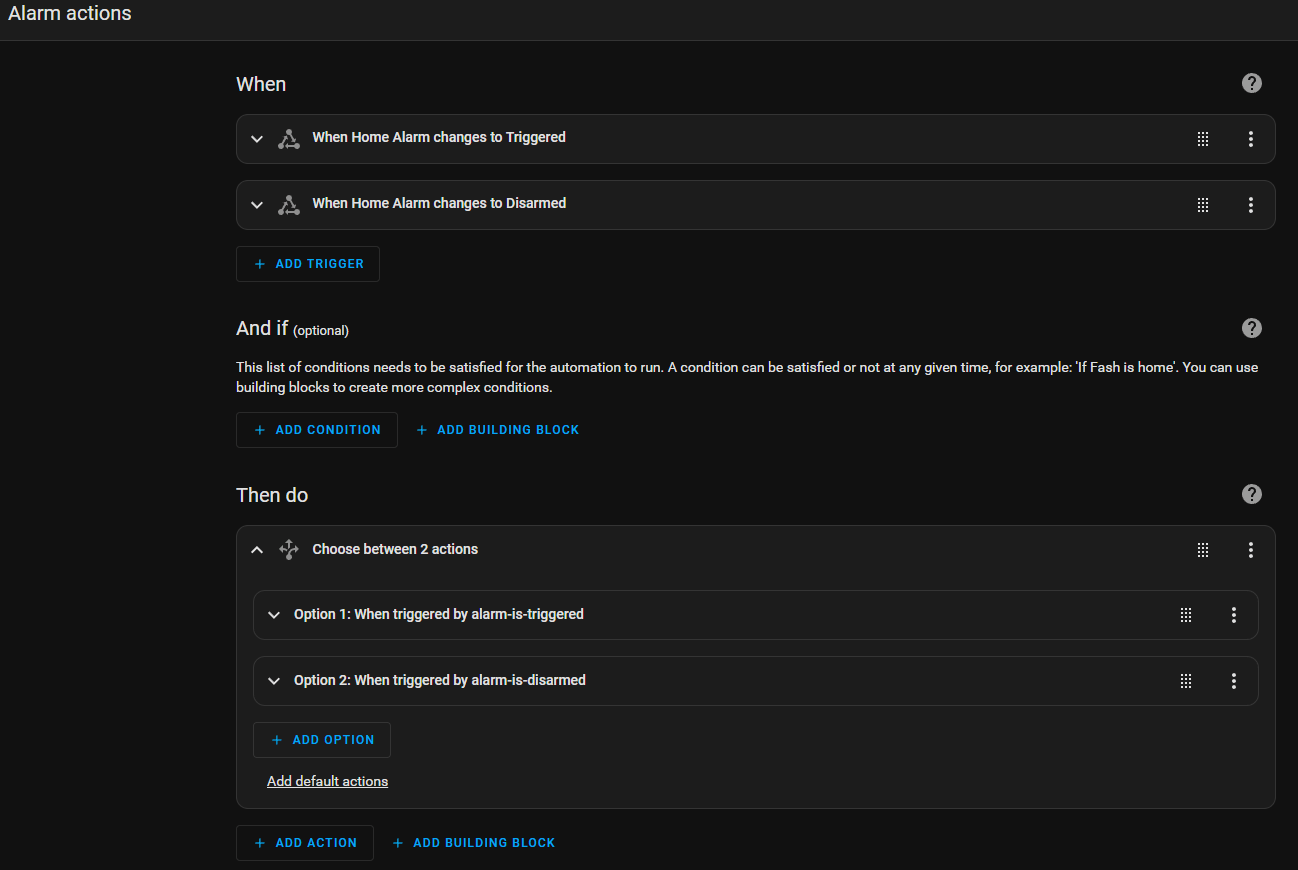
I used to have a “professional” alarm system, but it was too limited.
But when making a new alarm system using Home Assistant I thought I could reuse some sensors and the very loud alarm.
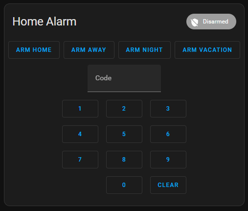
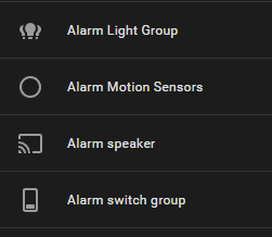
Setting up the Alarm within HA was as described on the HA website. I made a group for door and motion sensors. Then I made groups for lighting and switches.
Now I can “ARM” the house.
Motion sensors like PIR and camera sensors are being used for detection.
Lights and sound will be turned on when motion is detected.
When arming the system, the siren mode of the camera’s is also turned on.
When intrusion is detected I get a pushover notification on my phone and watch.
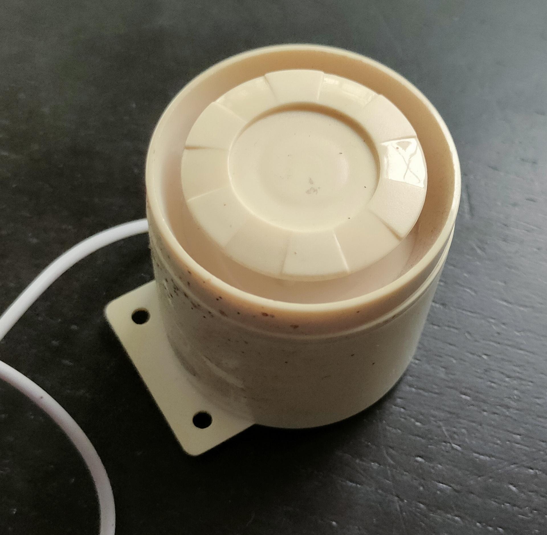
Wemos ESPHOME controllerOld (dirty) alarm siren
The siren is about 4-5 Euro’s on Ali https://nl.aliexpress.com/item/1005006066524139.html
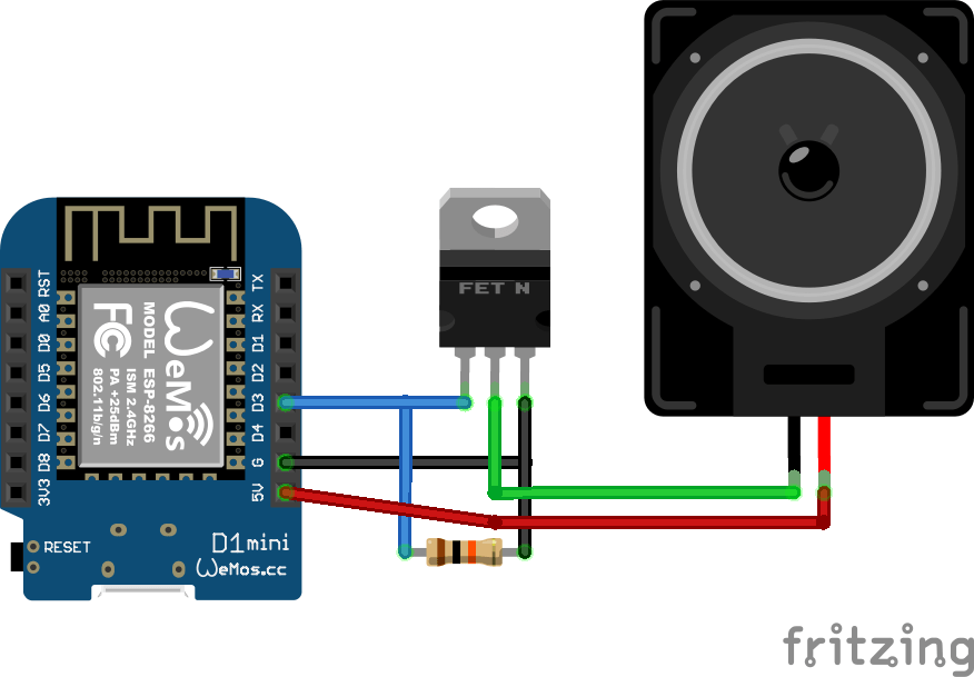
Schematic of the wemos controller
(I don’t have a Siren Fritzing part .. hence the speaker)
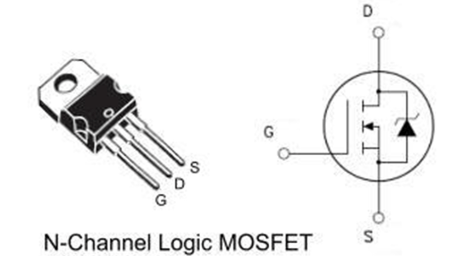
Used mosfet is a N-Channel 30N06L, resistor is 10K
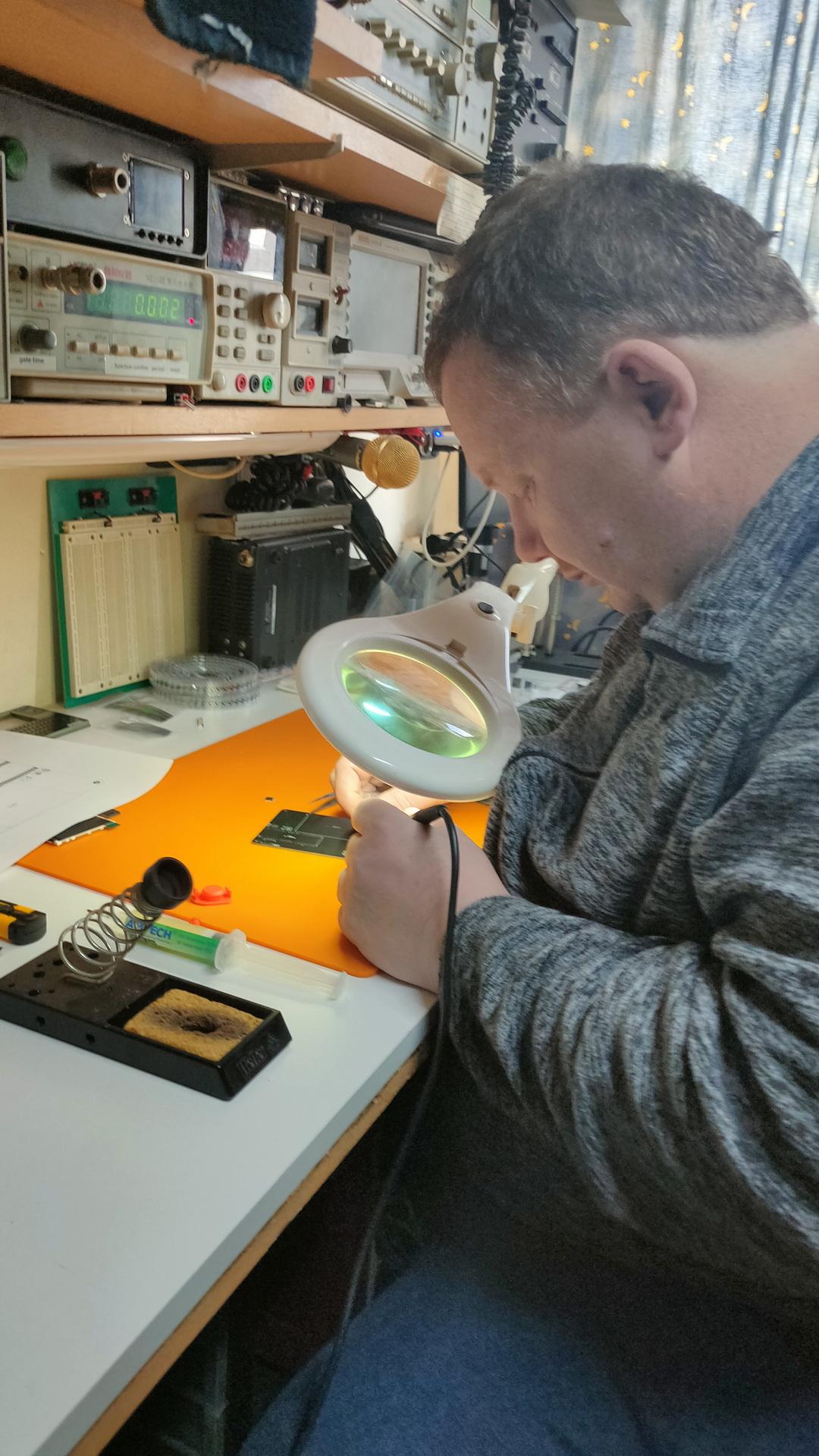
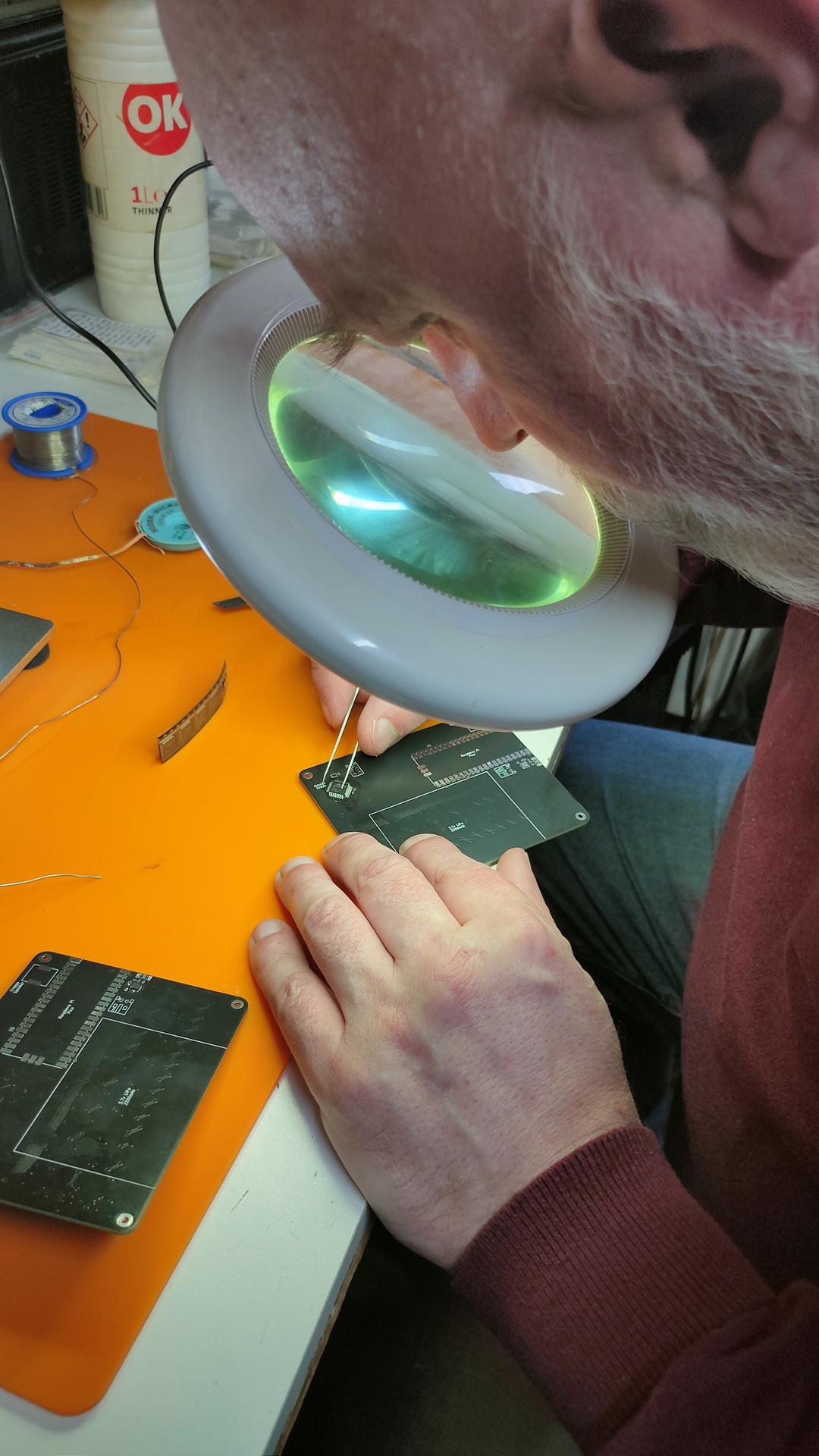
I was afraid to start this myself, SMD is on another level for me. But my good friend Marco said … No problem!
So I ordered components online, which was not easy. Selecting the correct parts, sizes and options.
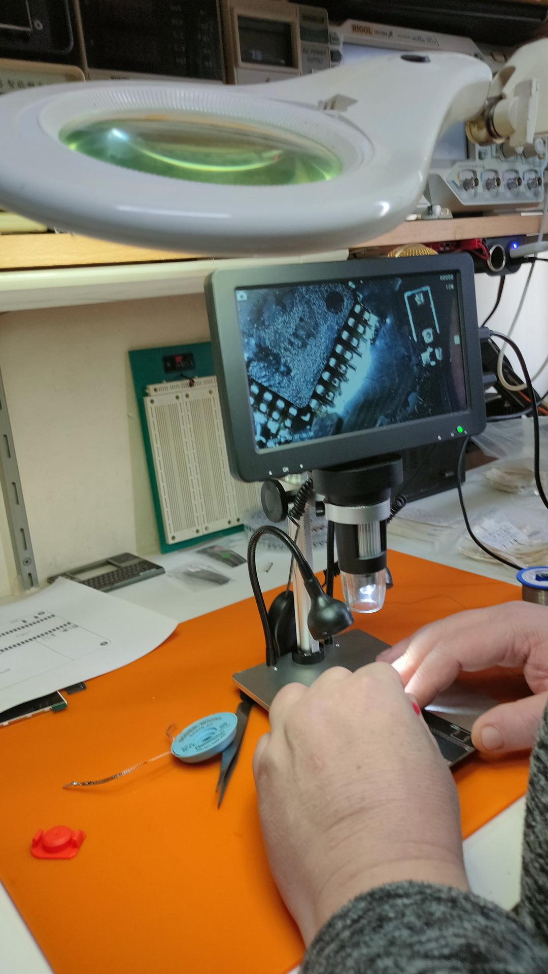
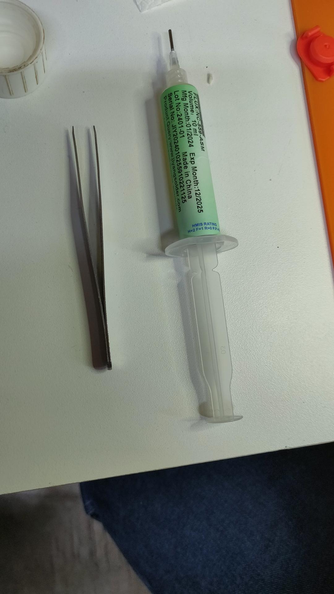
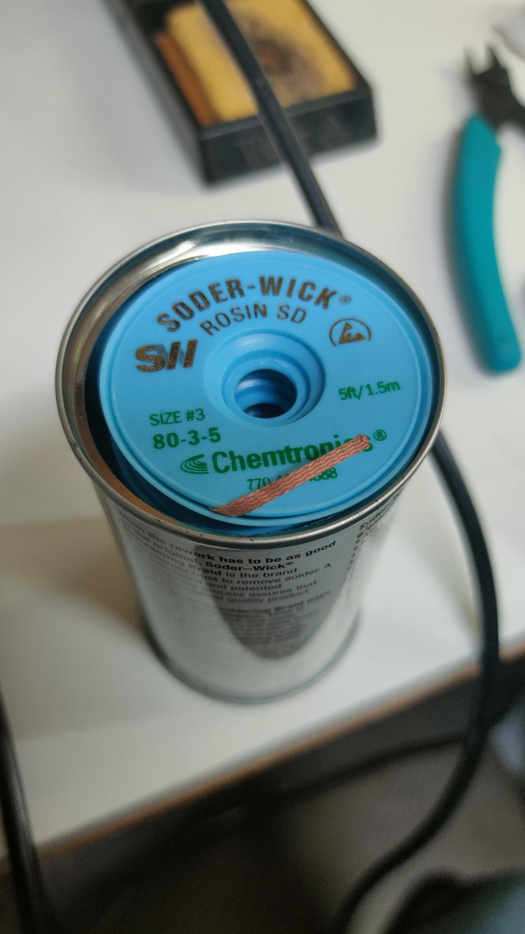
Finding orientations of the componentsThe master at work, he has always been our soldering master (see GPC)Using a microscopeFluxWickI have to do one myself
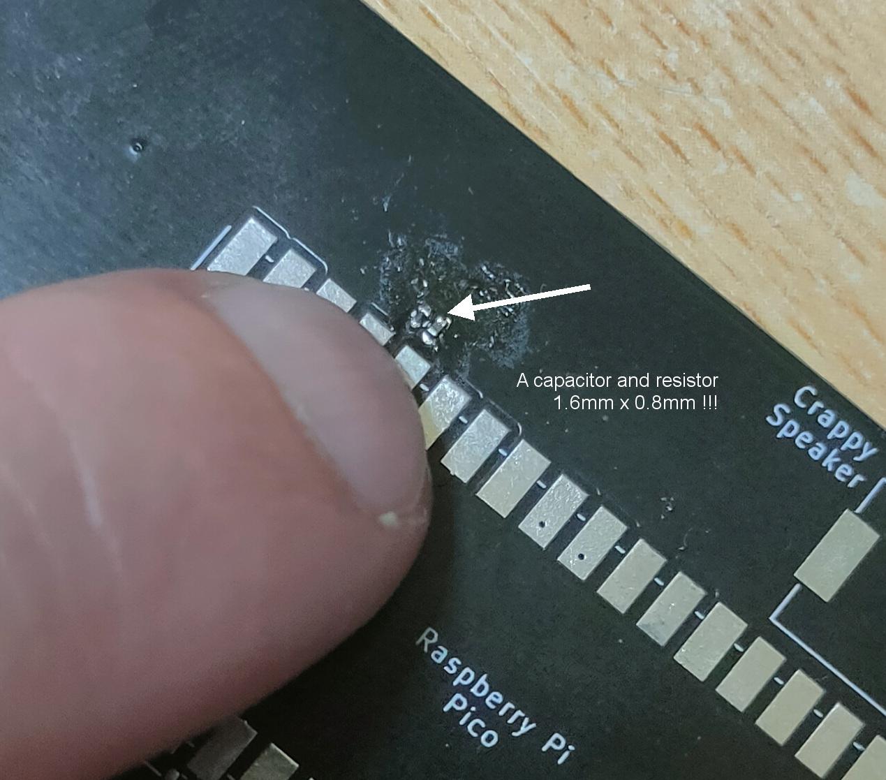
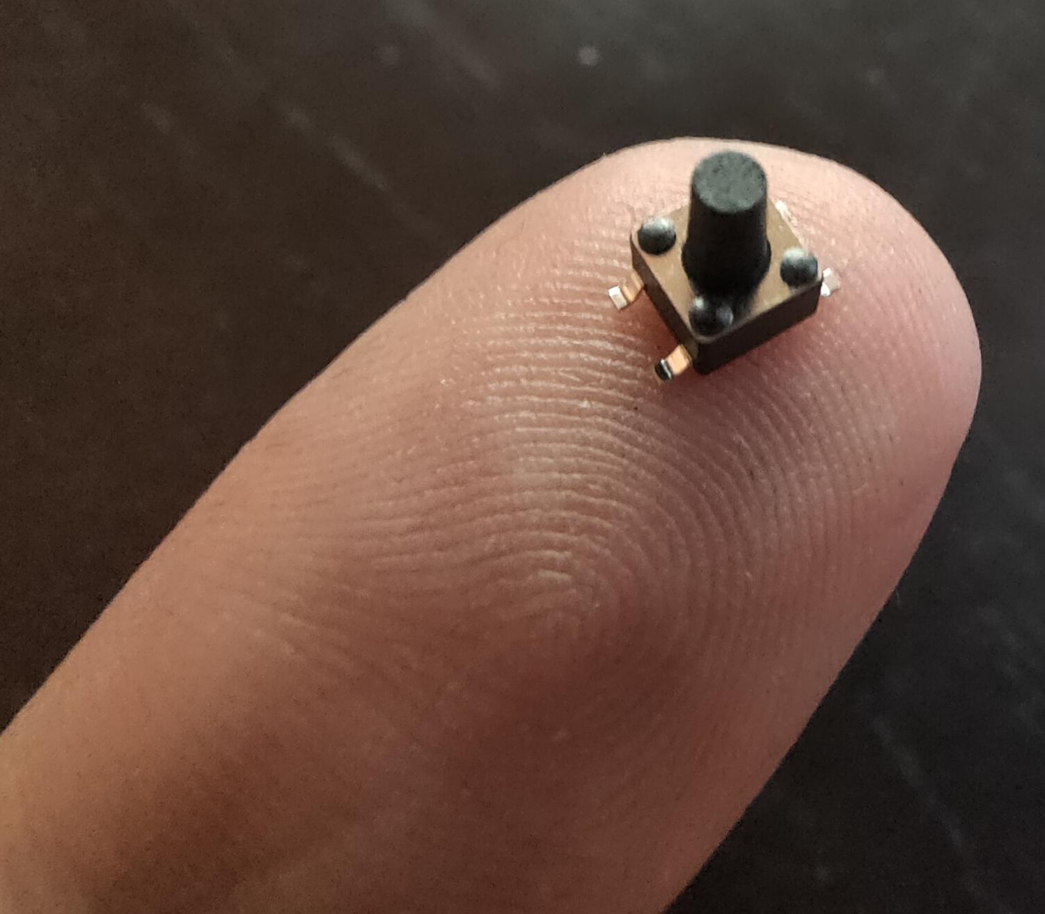
These things are really really small
1.6mm x 0.8mm40 connections / 20mm !
Using tweezers to place the components was even difficult. The slippery tiny bastard got catapulted everywhere. (Or got stuck on fingers, soldering iron and alike) Many small components got lost into the 7th dimension. Never to be found again.
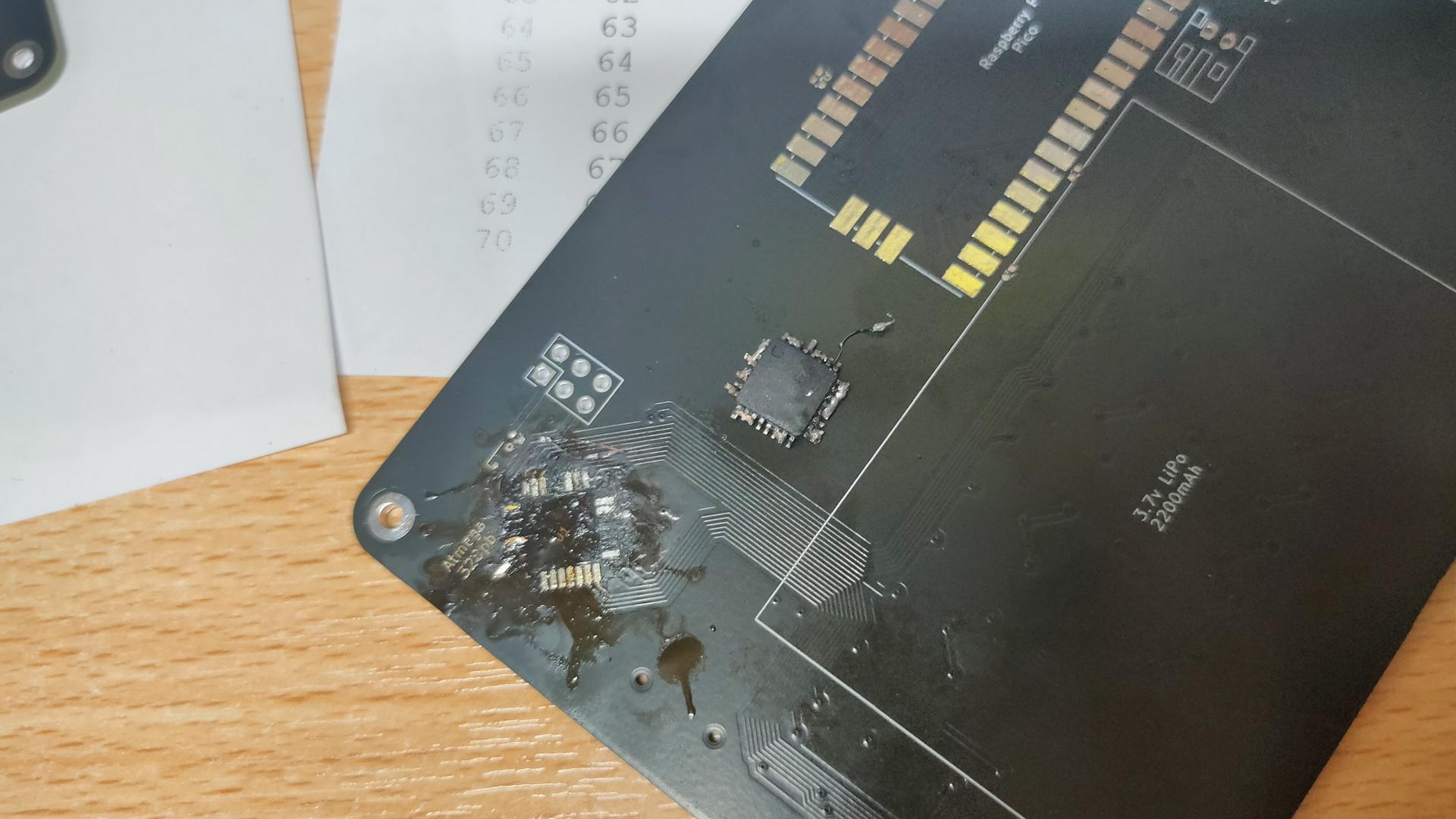
Awesome to work on this together, but Marco said that I have to try it myself. Welllll, I got 3/4 of the ATmega328PB-A perfectly soldered, then I notished that it was crooked. Desoldering was a mess, and I heated the PCB TOO much with the heatgun.
My messed-up PCB, and f*cked-up IC. Leave it to the professionals.
Next step for me is soldering the 75 mini buttons!
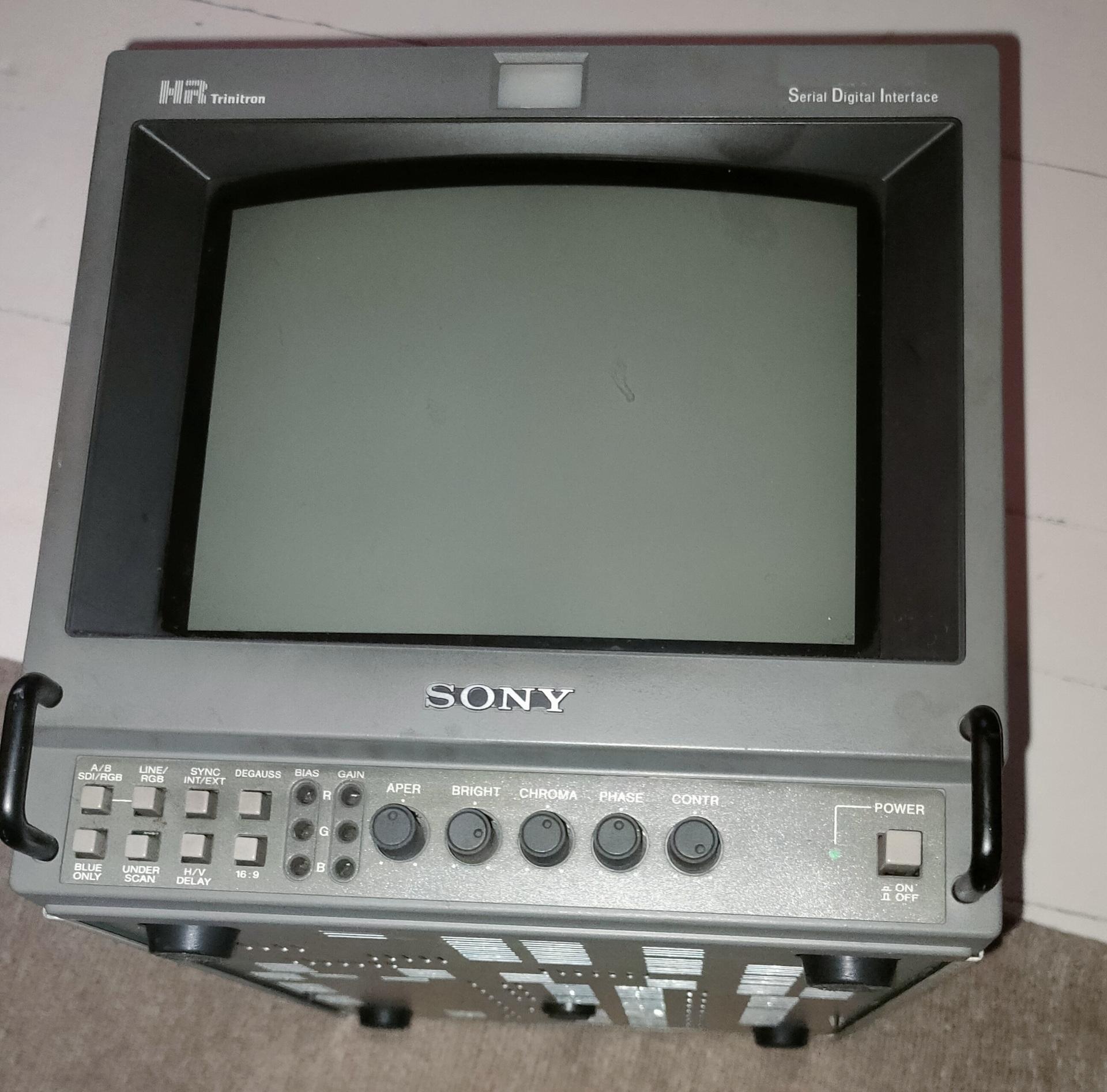
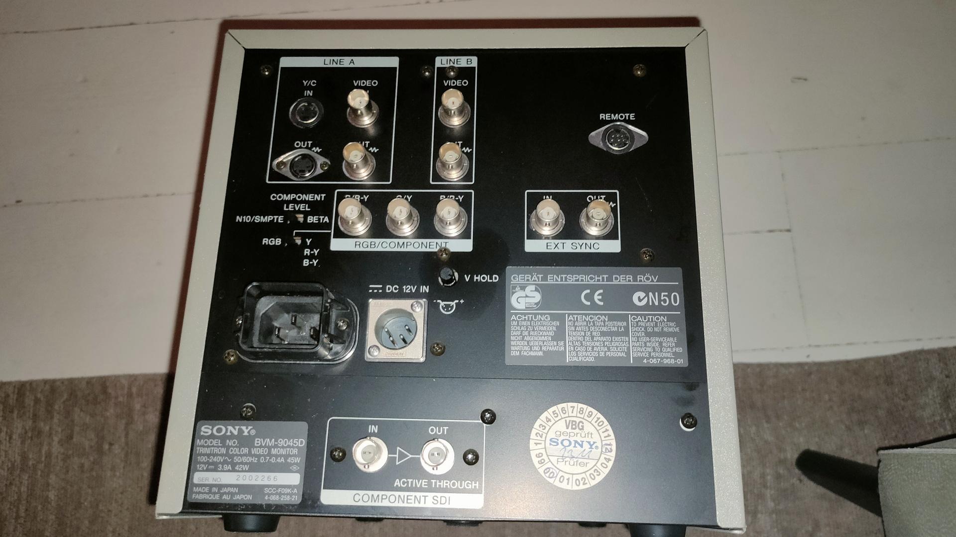
Got a Trinitron display from him, I was looking for this for a long time.
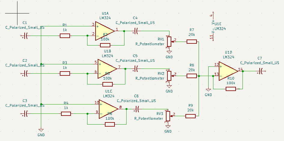
At the back the 8 pin single channel lm368 amplifier. At the front the 3 channel setup. I still have to tweak the resistors, and potmeters. Then I can make a permanent PCB, and figure out the connections to the 6502.
At the moment, the Arduino Nano is playing some real sound samples by using the registers of the sound chip. The music is being played by sending the register dumps directly to the chip.
Much like i’ve been using SID register dumps to play songs in another project.
This is version 0.1 .. do not use. If its wrong, or can do better please mail me. Oh it needs a 1k resistor from the 20K’s to ground I think.
I was working on a MCUME proof of concept, with my own compiled version. But my combination of a Pico and an ILI9341 display didn’t work.
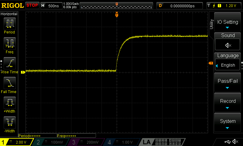
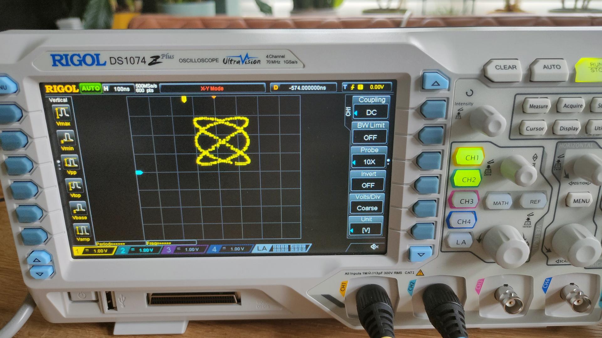
Luckily, a package arrived. My new scope!
A Rigol DS1074Z+ oscilloscope! The replacement of my CRT version.
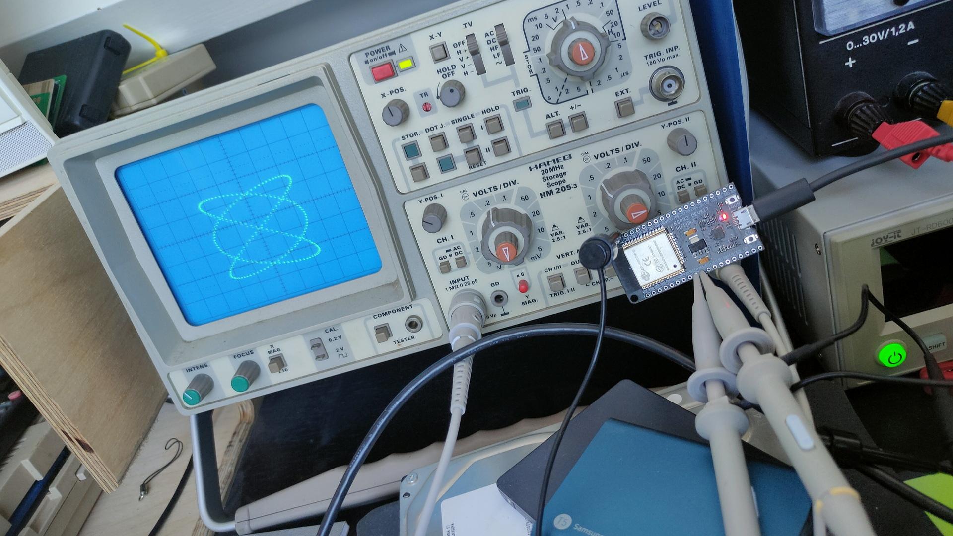
My new RigolThe old Crt versionNew and old, both with the ESP dual sine demo i’ve posted about.
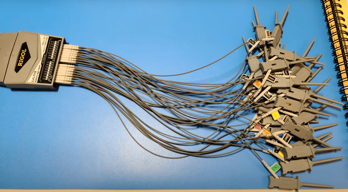
This new oscilloscope has 4 channels AND there is a add-on for a 16channel logic analyser.
For my next birthday?!? 🙂
The Rigol can be connected to a wired network. So that’s one of the first things I did. (It came with all software options enabled, so no need to ‘fix’ those)