This week (while preparing for a mini retro party) I fixed some Amiga stuff.
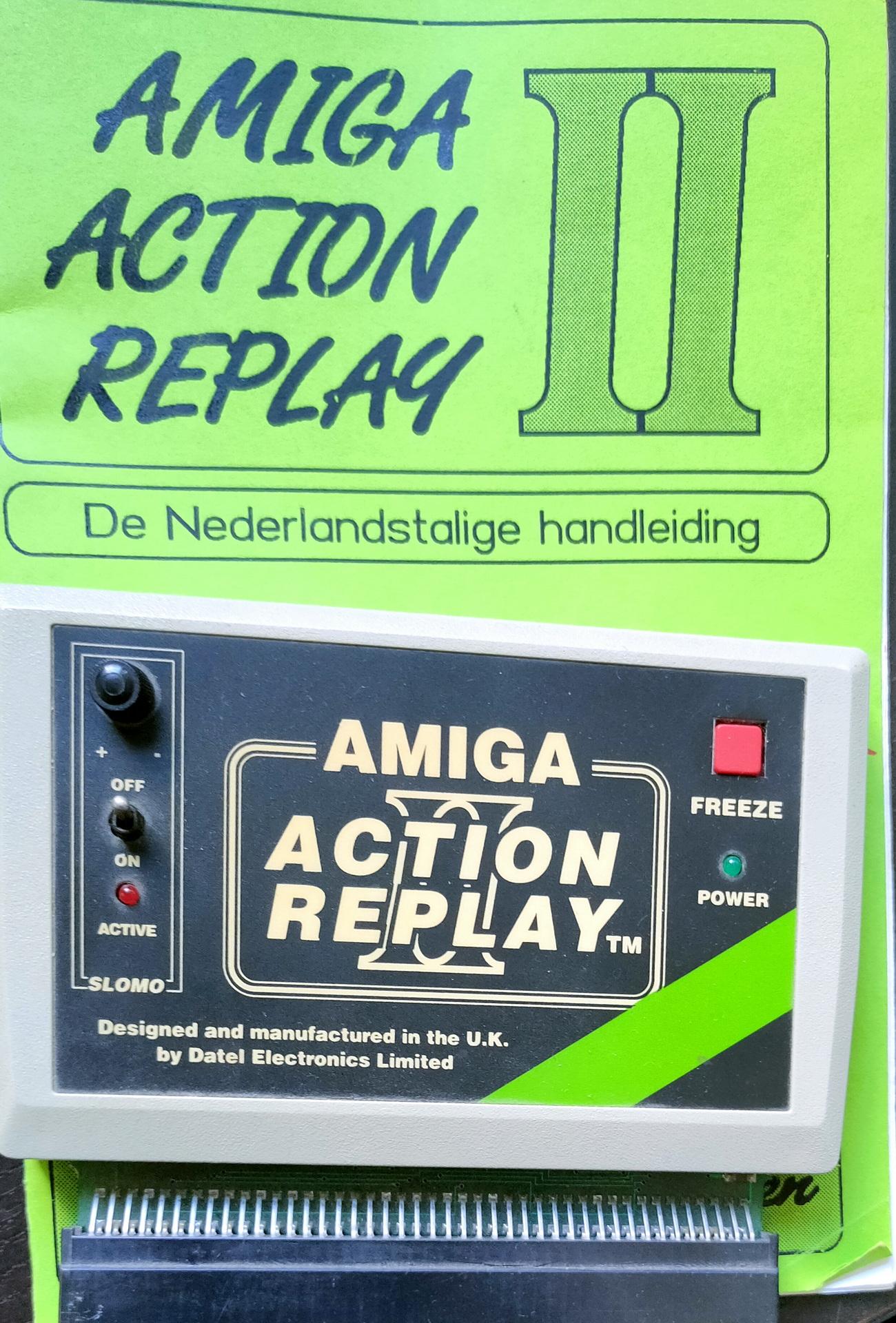
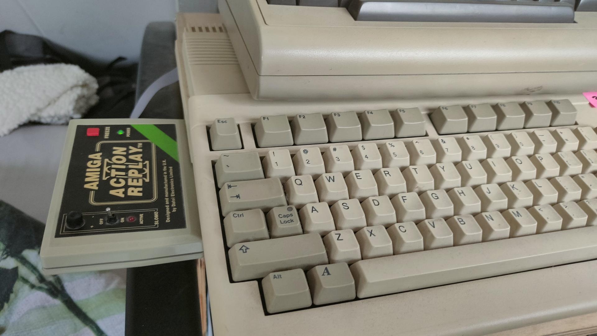
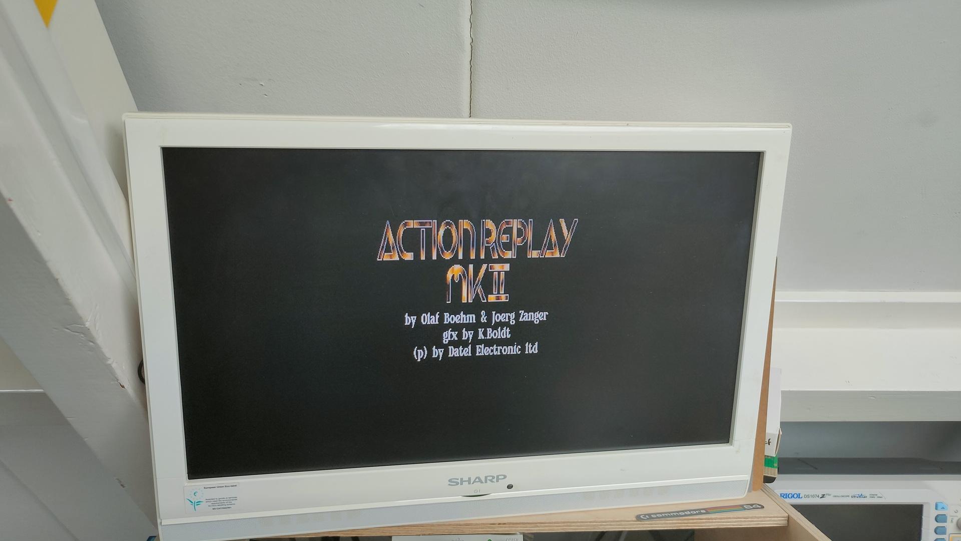
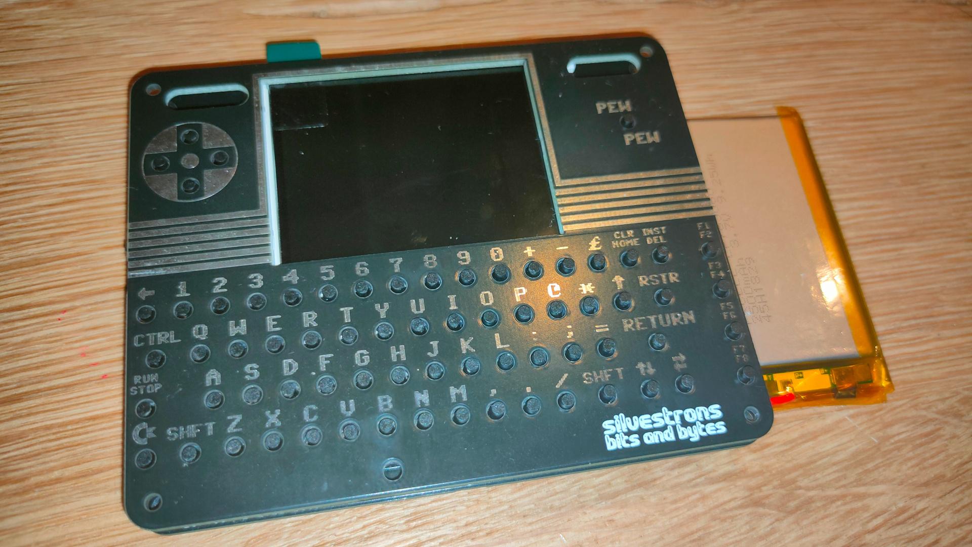
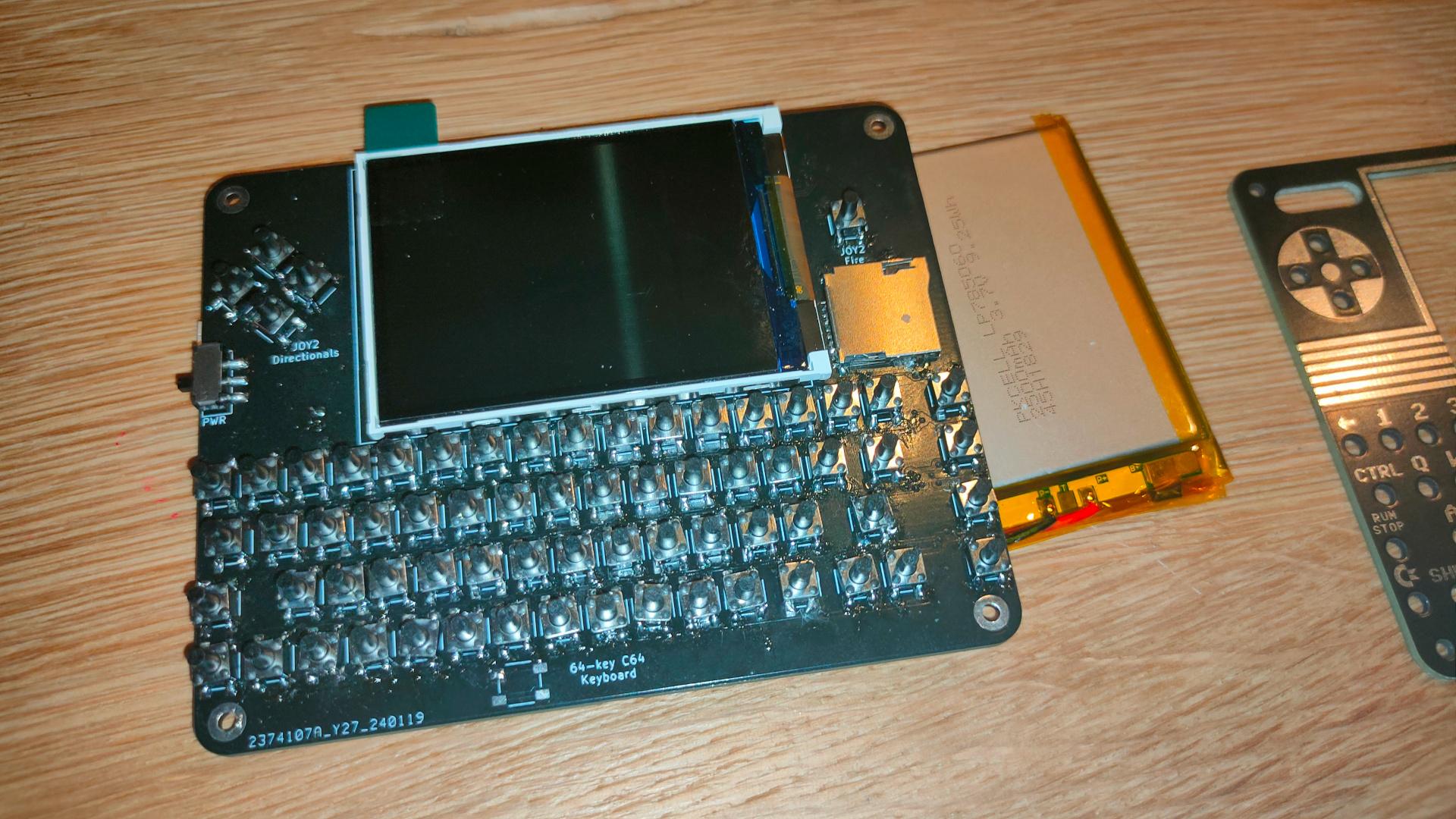
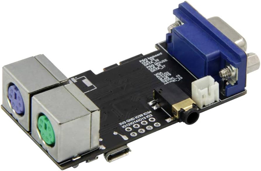
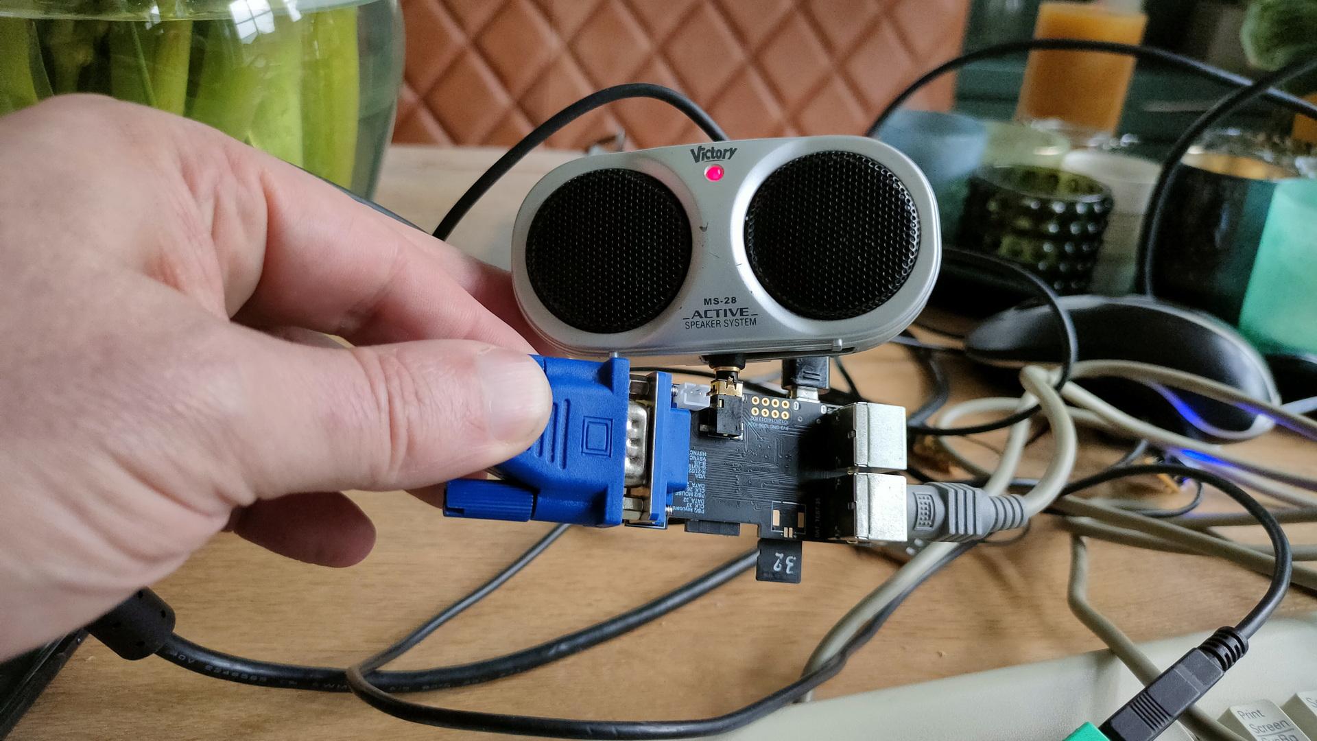
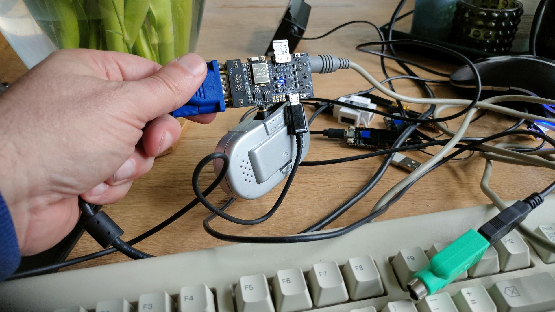
I’ve bought a new gadget.
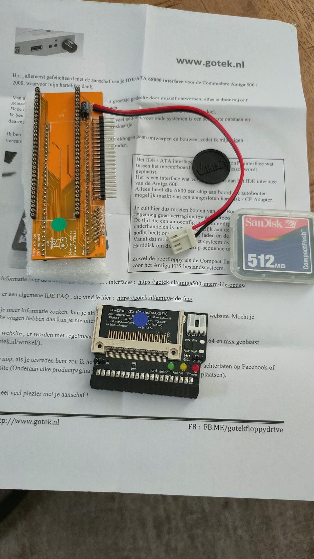
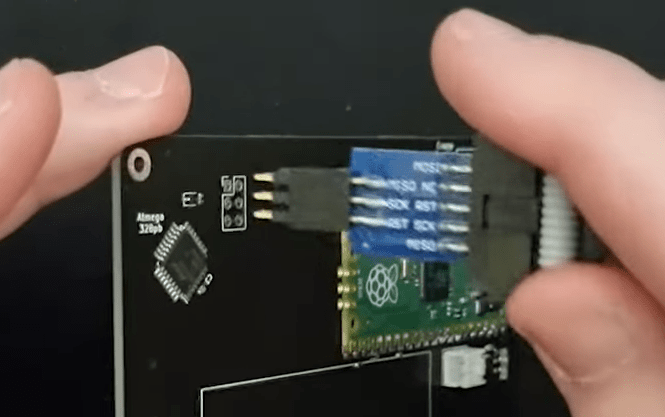
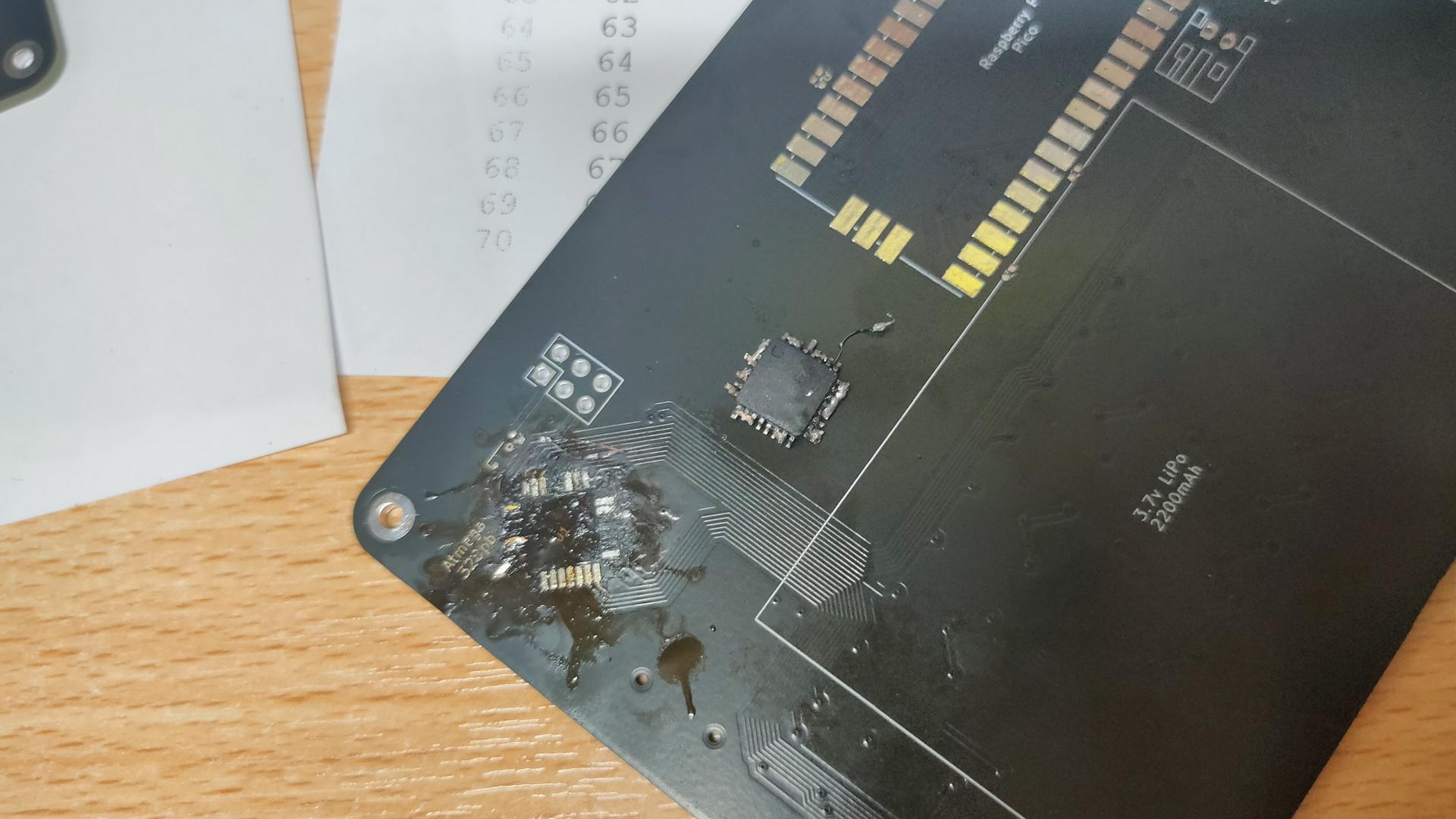
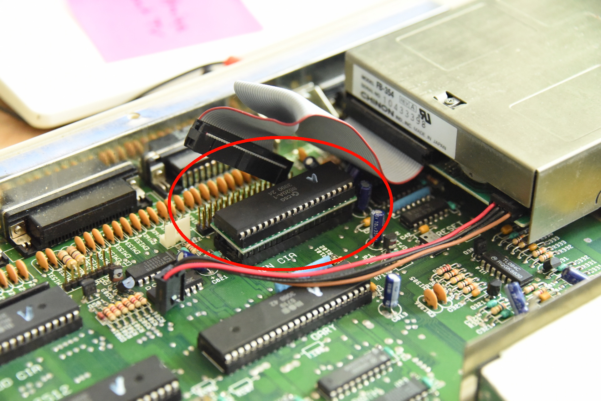
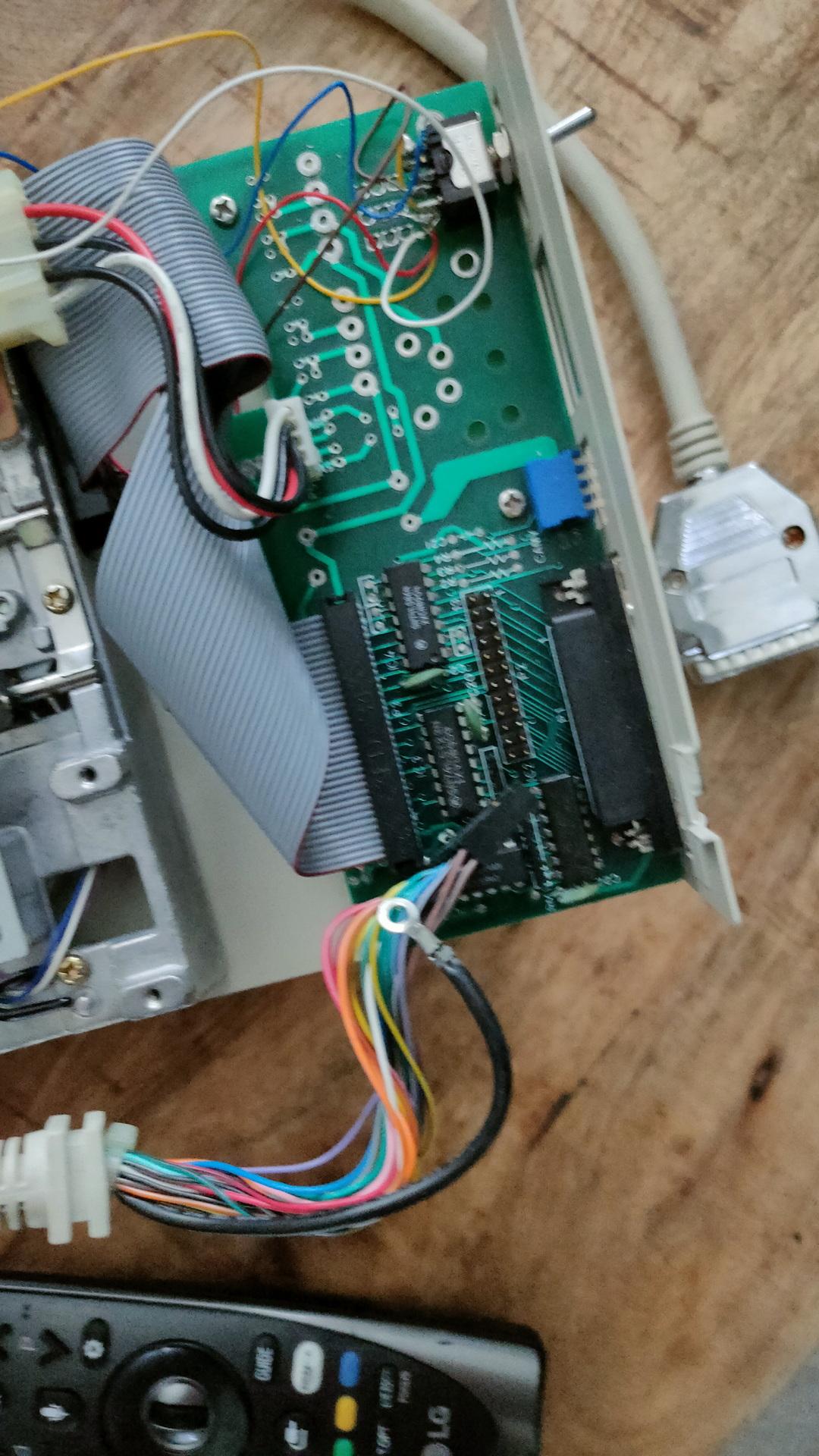
You place this PCB between the CPU IC socket and the CPU (68000) itself.
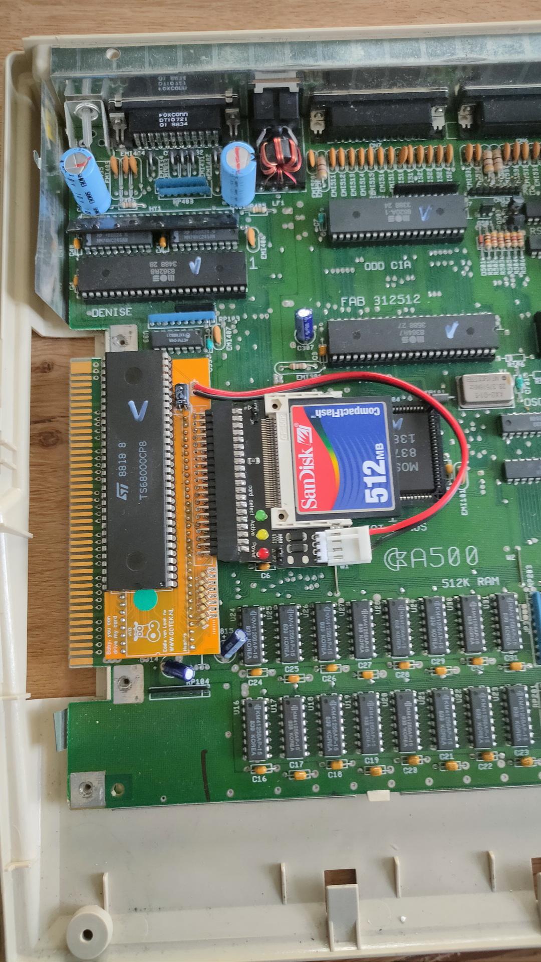
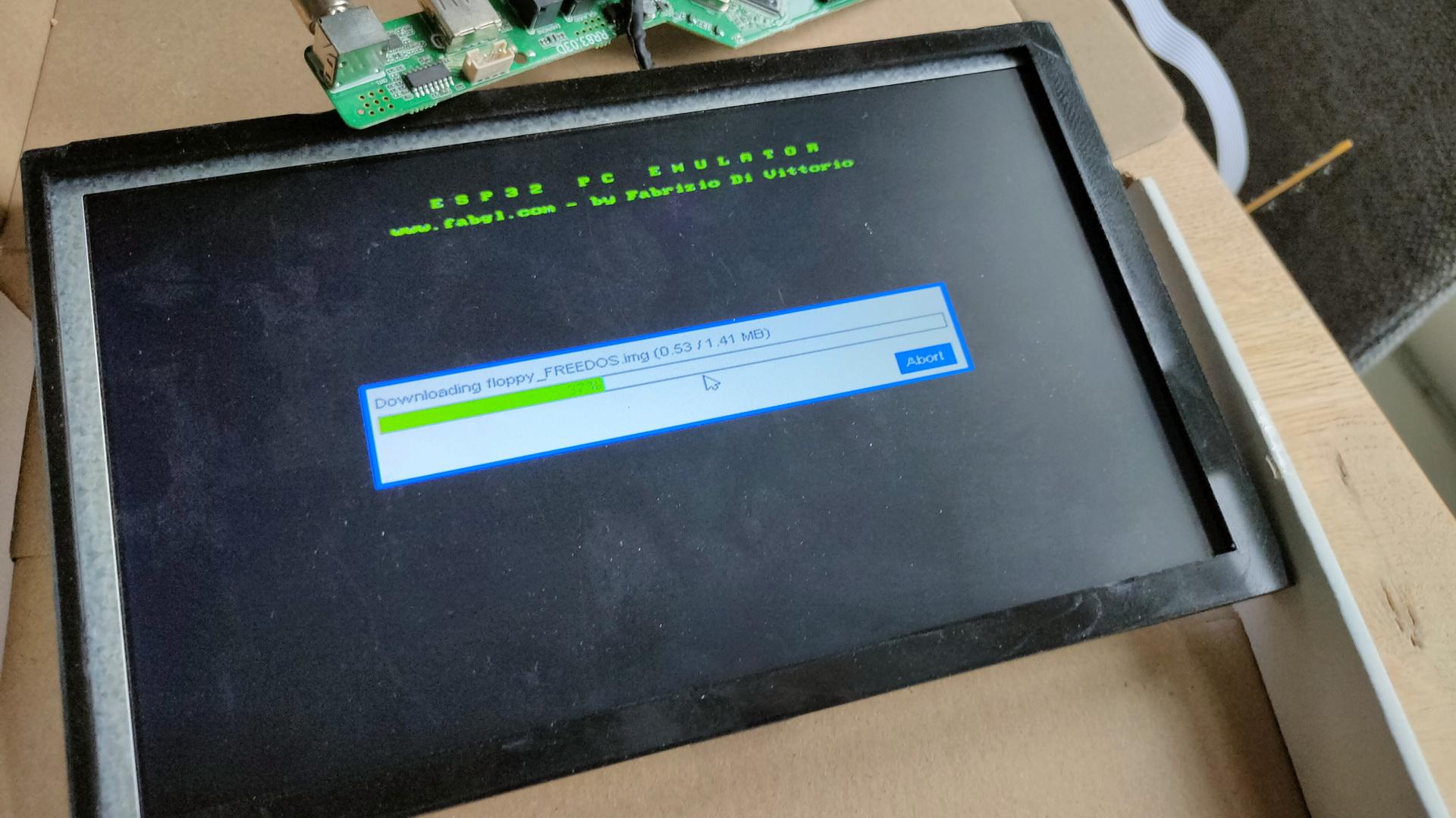
Now running a special floppy image, which loads a driver, I can use the 512MB sdcard as “harddisk”.
It at first ran into all kinds of hangups.
Checking everything, I found CIAB (8520) the culprit.
Timing errors I’ve never noticed before!
Switching this one with CIAA resolved the problem.
(I don’t use a printer anyway, but I have to remember that anything using the parallel port can have problems now.)
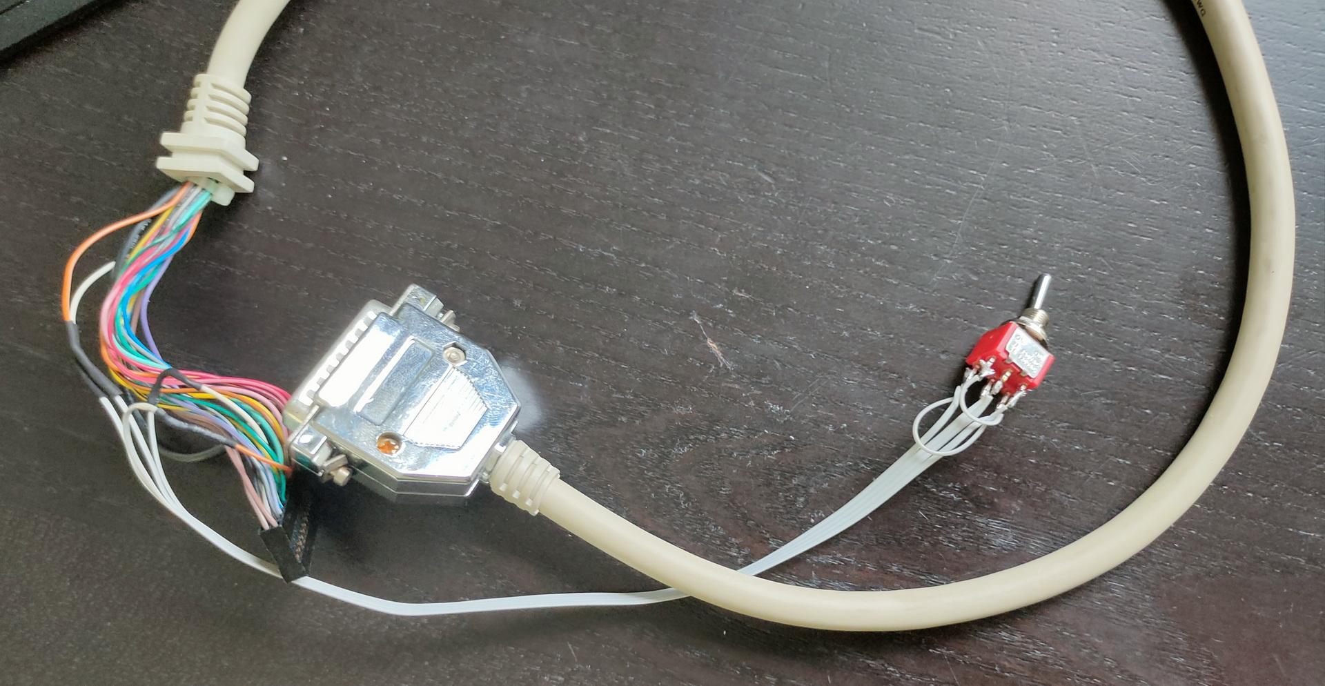
Meanwhile, I wanted to have a better control over the Amiga drives, so I’m planning to use a second switch to reassign drive numbers using a switch.
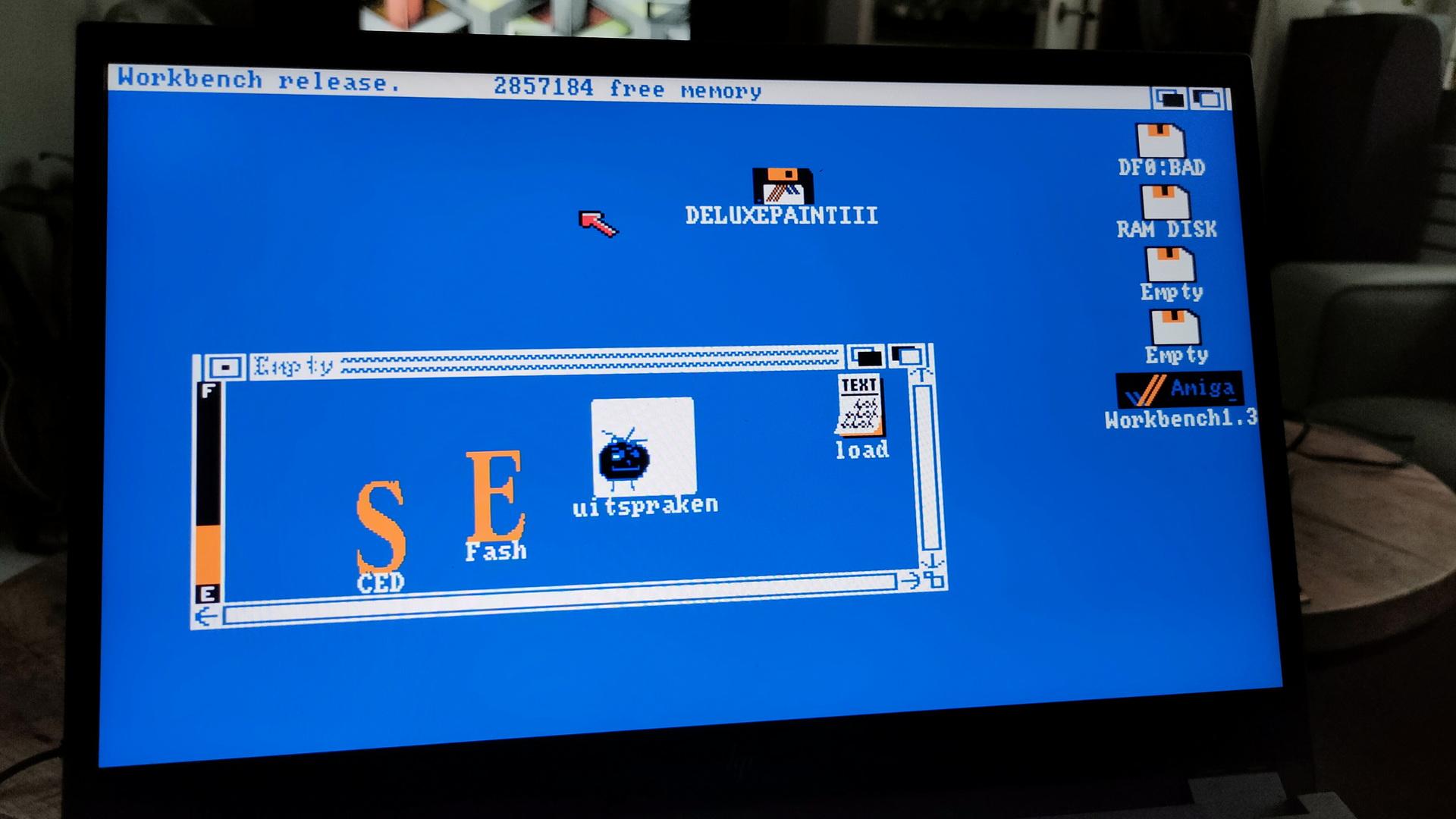
For switching Internal/External drive (df0/df1) I was using a Gotek boot switch. (Just press 3x ctrl-Amiga-Amiga)
See https://www.henriaanstoot.nl/2022/05/14/gotek-stuff/
But I have TWO external devices.
The Gotek virtual disk device and a real 5.24″ drive.
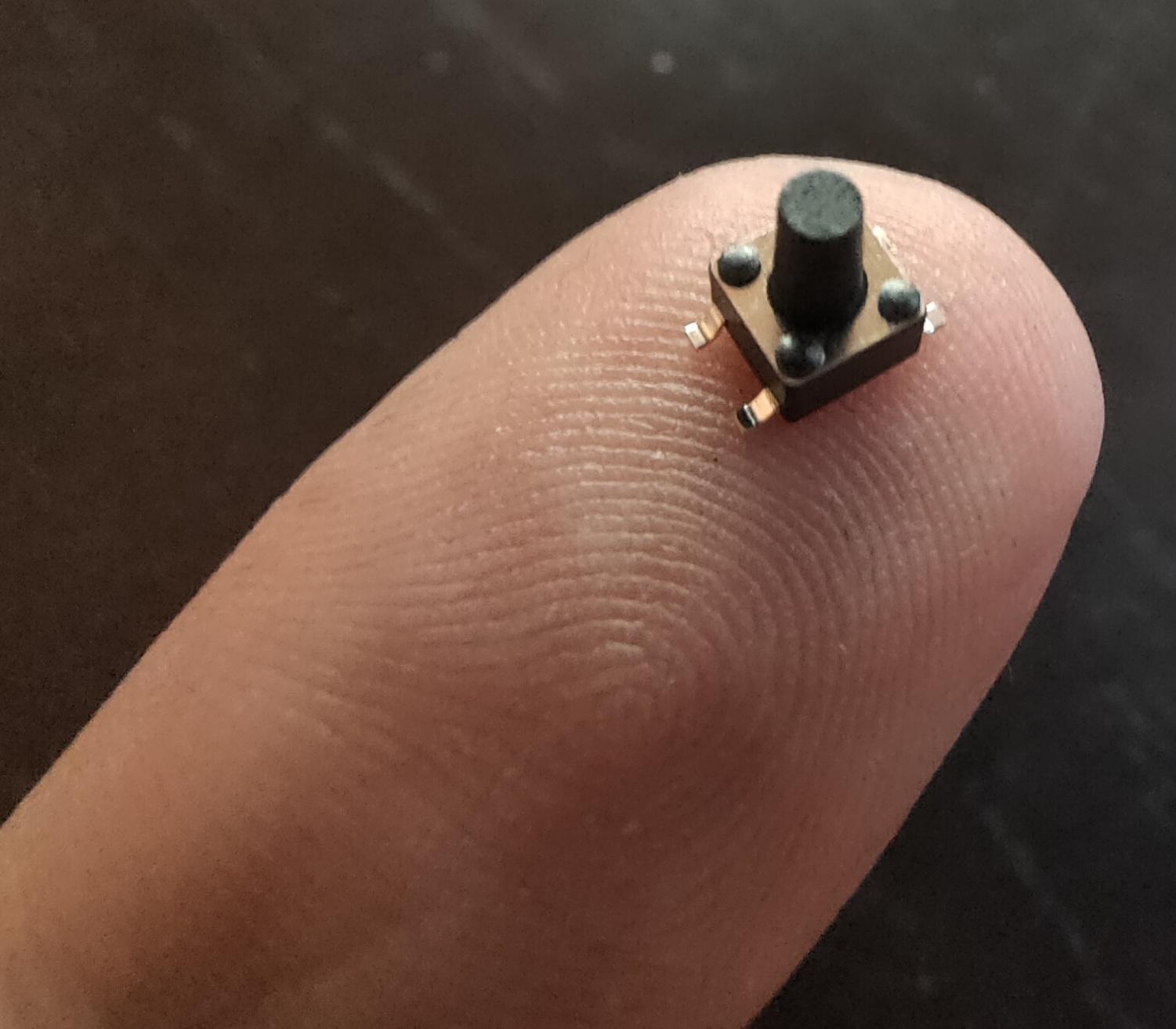
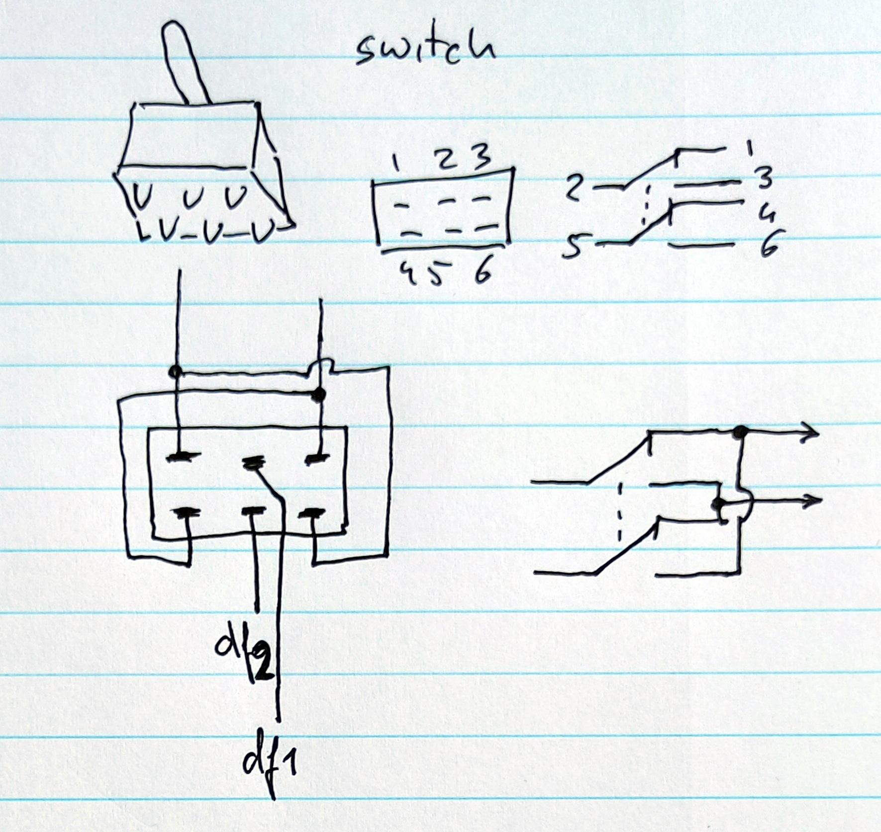
So I’m going to use a ON-ON double switch to toggle the external devices.
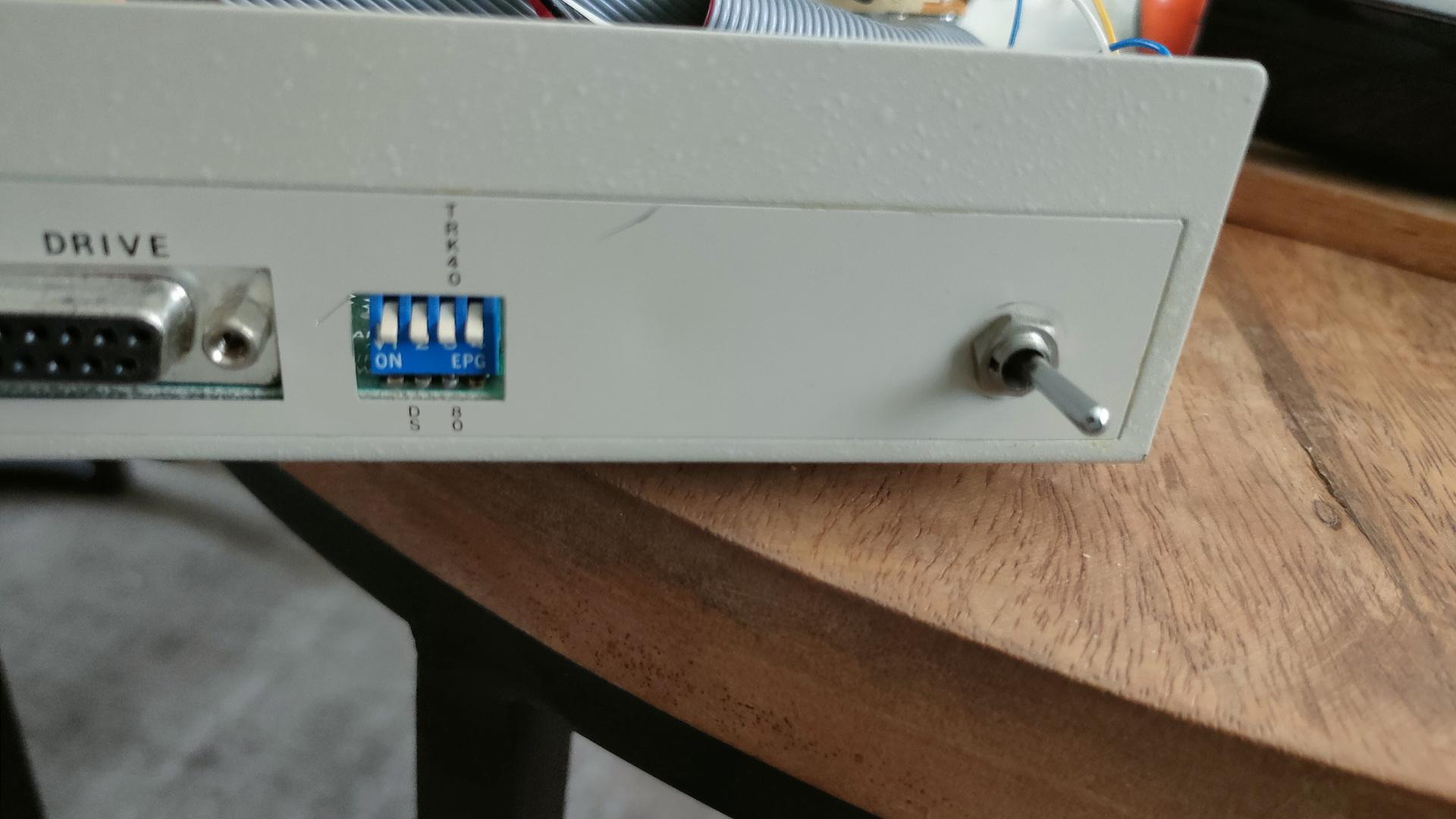
The internal switch toggles internal and external.
The secondary I’m going to build into the 5.25″ drive toggles df2 and the “df1”.
That way the internal drive can be 0 (boot) or 1.
The external drives can be 0,1 or 2.
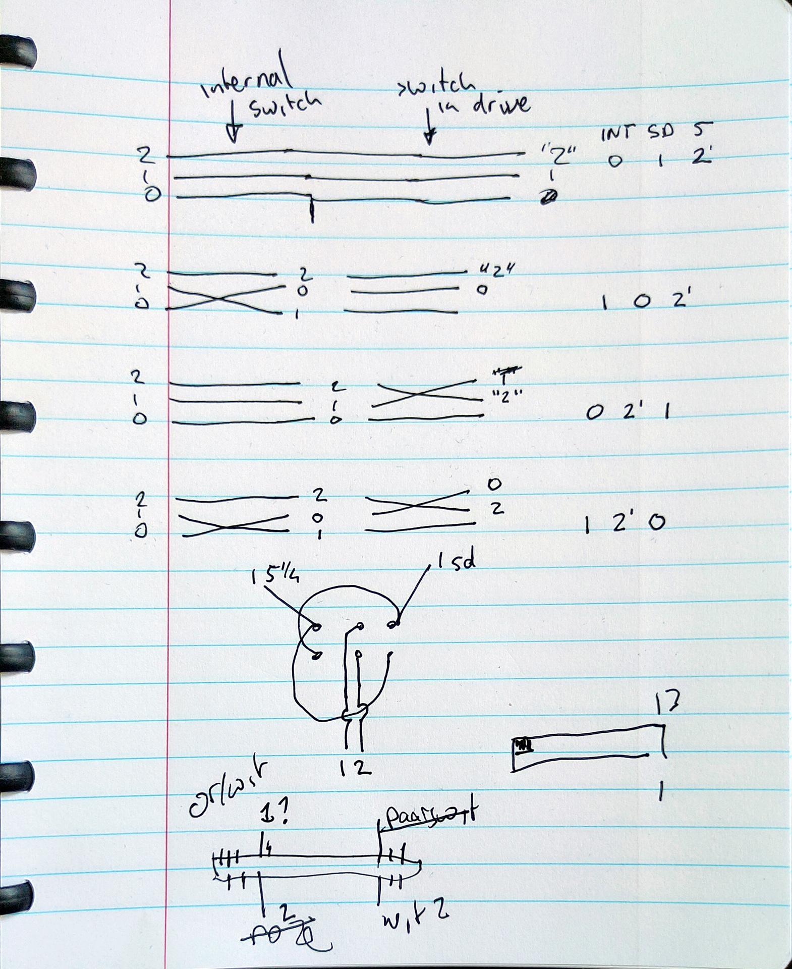
NOTE: Switch pin 21 and 9 using the cross switch!
SO: Amiga with internal drive -> External 5.24″ which has a passthrough to the Gotek.
Another amiga thing fixed:
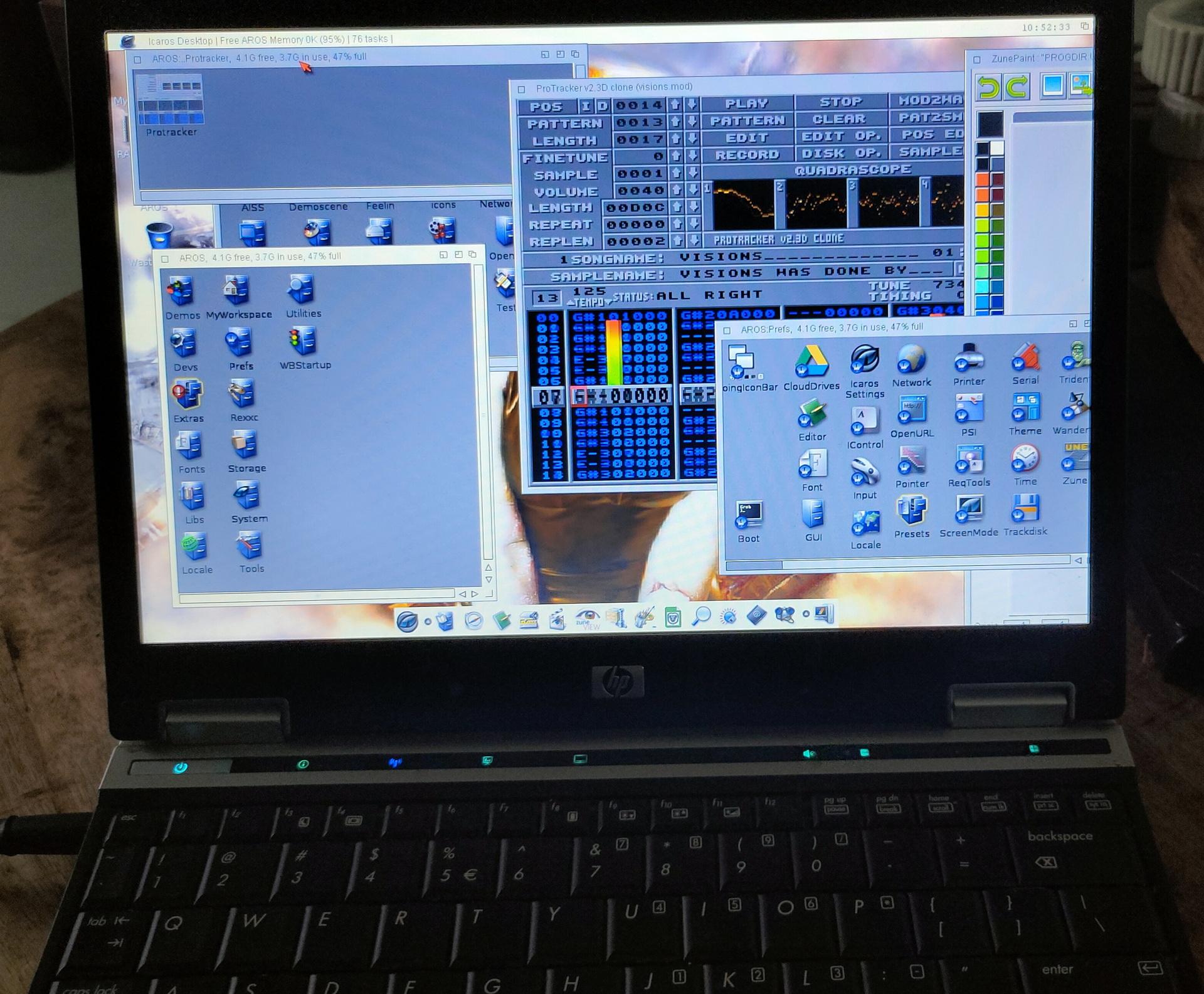
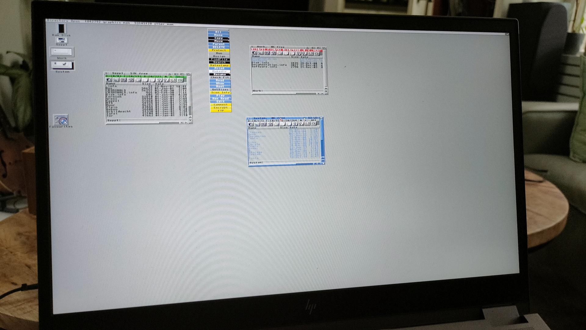
I re-installed Aros (on an old Laptop this time)
And third: I’ve bought the Amiga Forever cdrom.
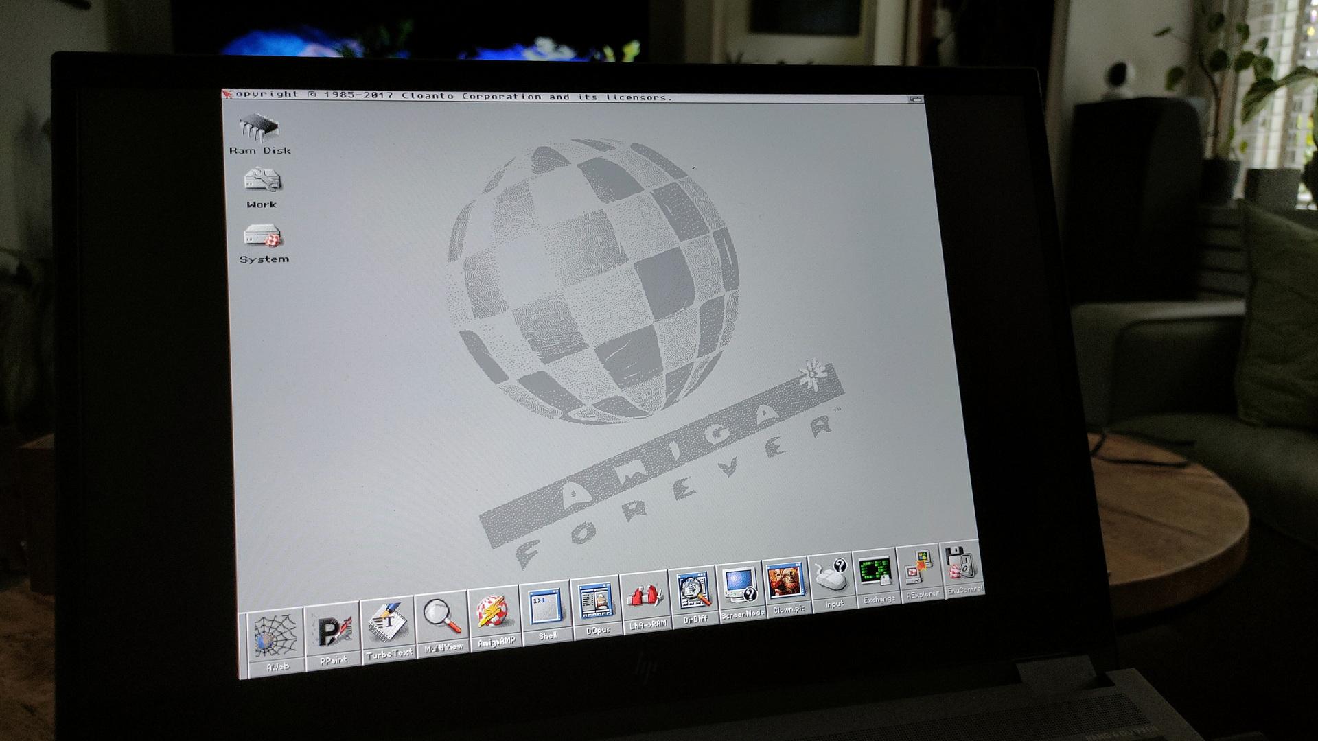
When you get the ISO image from AmigaForever, and want to run it using Linux, do this to get it working
sudo apt install xkbfile1:i386
sudo apt install libxkbfile1:i386
mkdir -p /cdrom
sudo mount -t iso9660 ~/Downloads/AF.iso /cdrom
cd /cdrom/Private/Linux/e-uae/
./kxlight-start.sh

If you install Wine, you can use the windows gui in linux also.
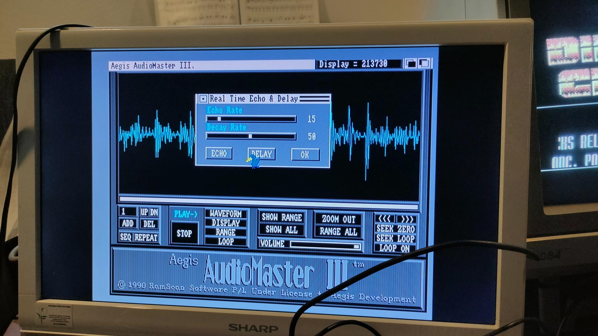
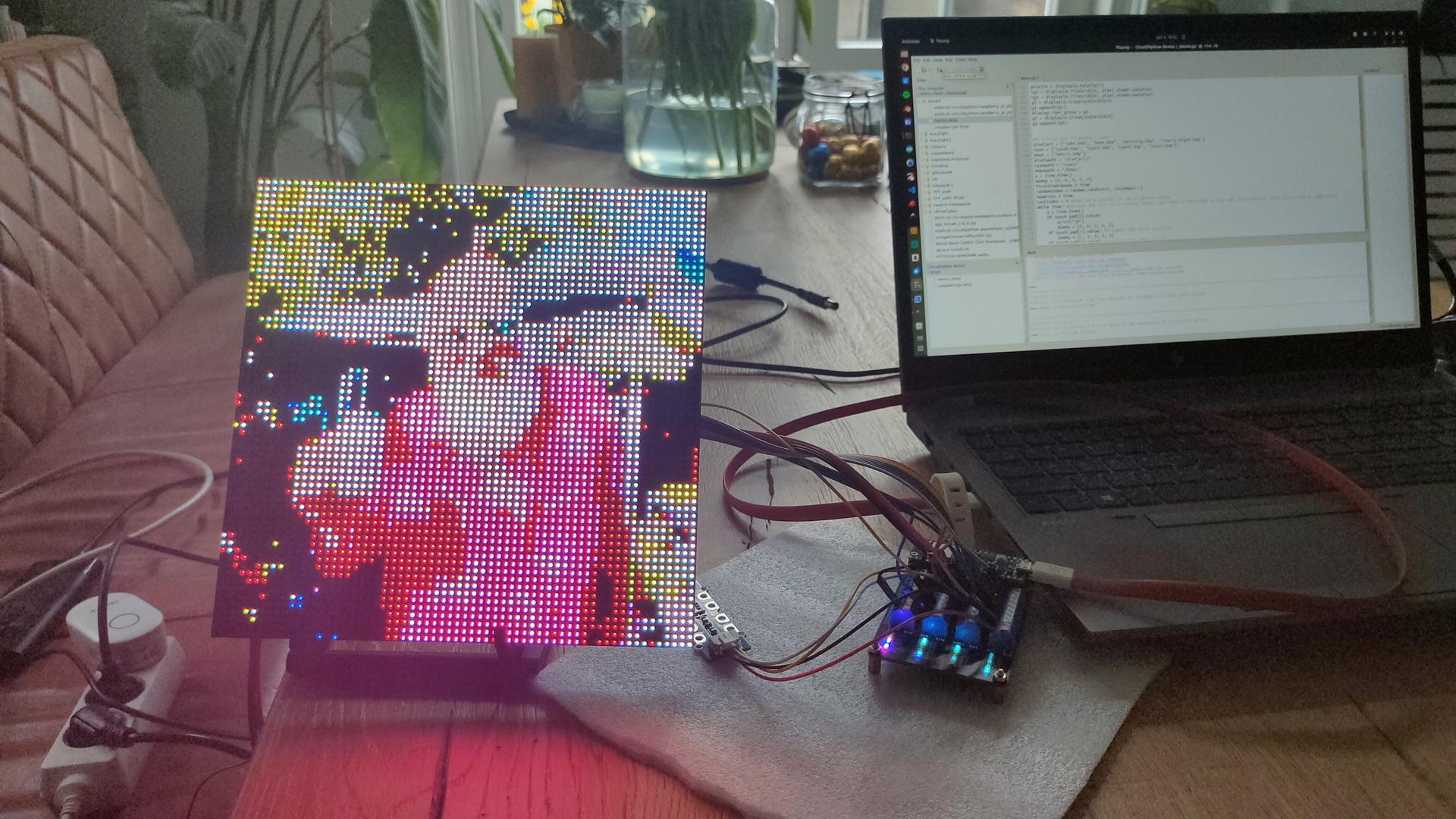
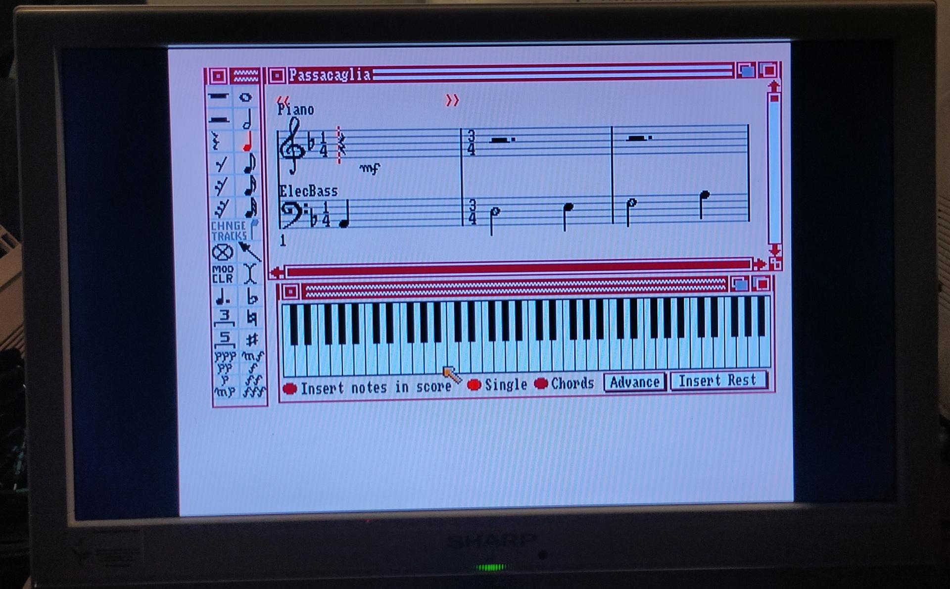
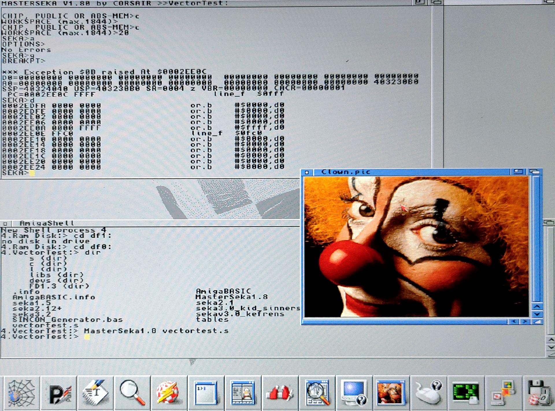
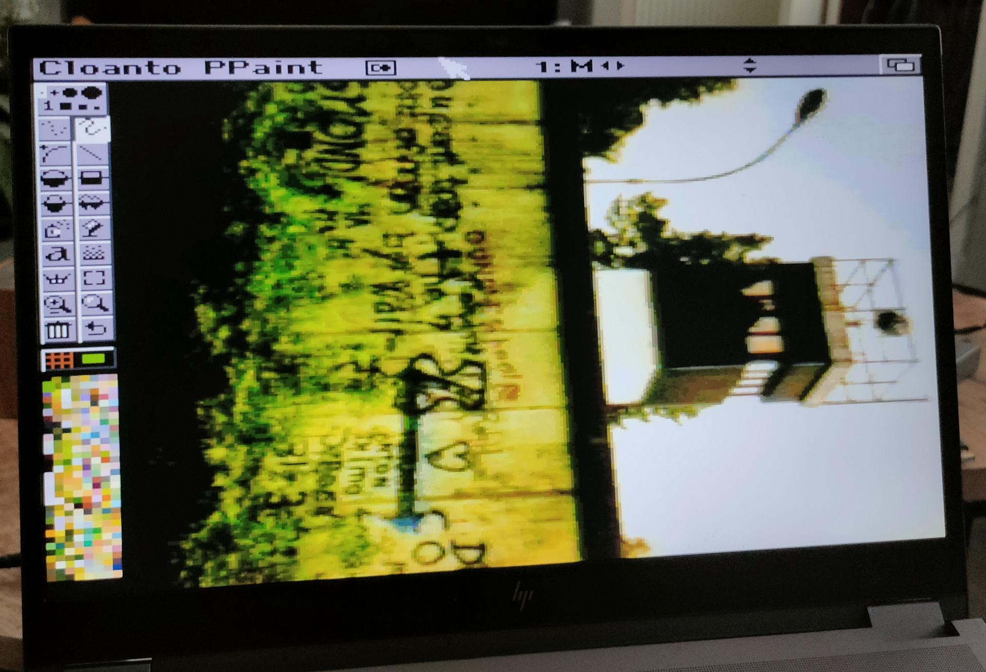
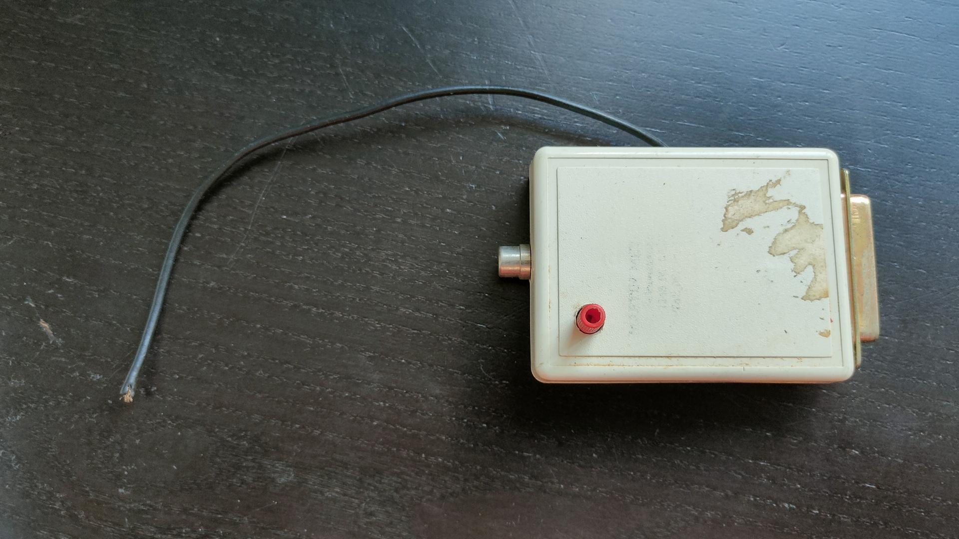
Amiga samplers
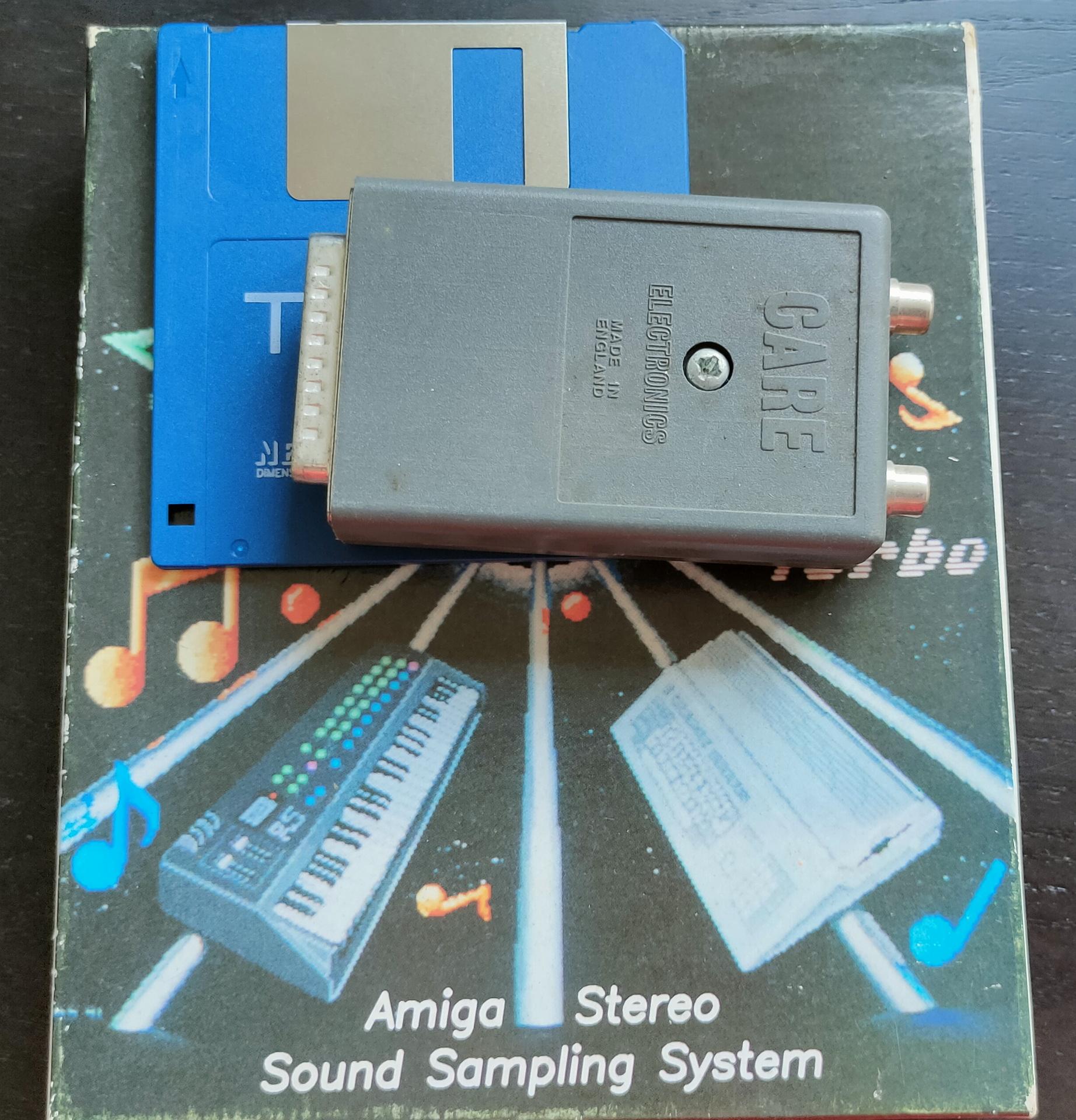
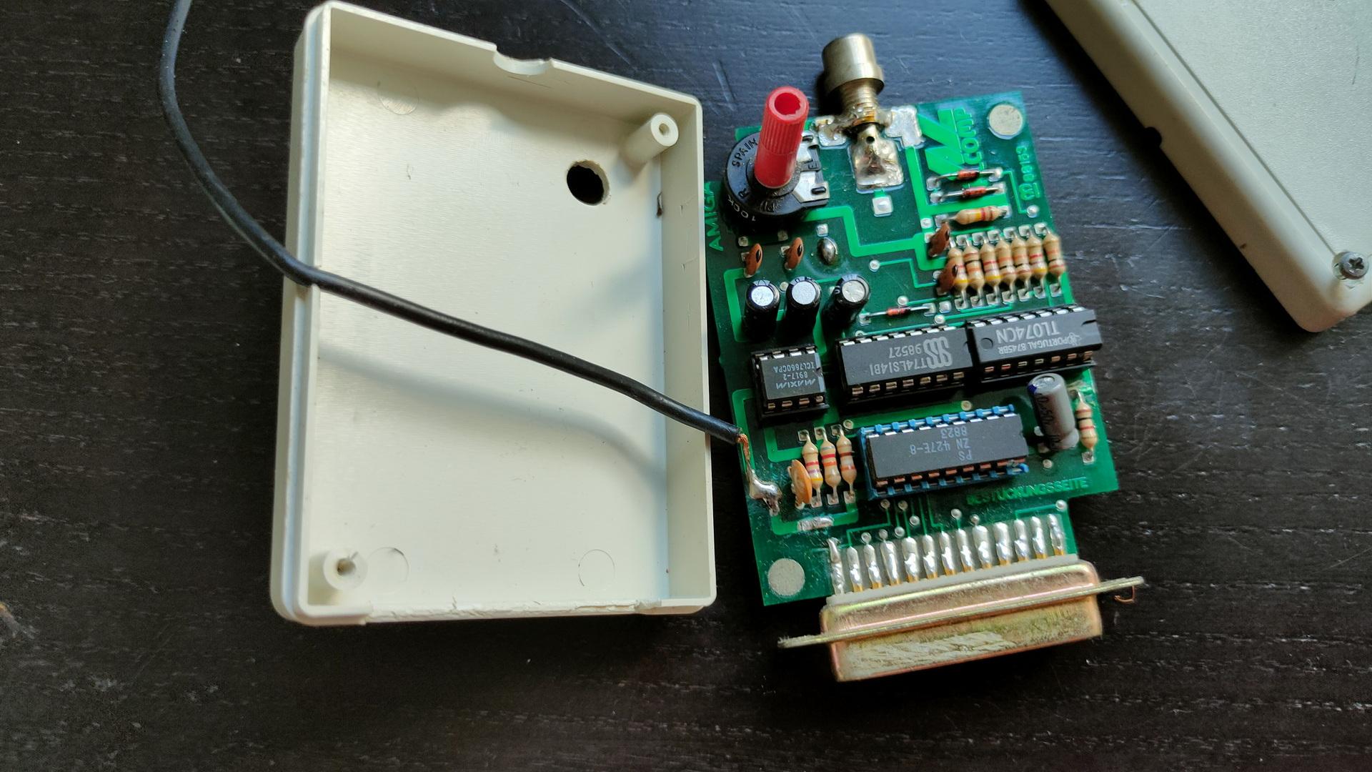
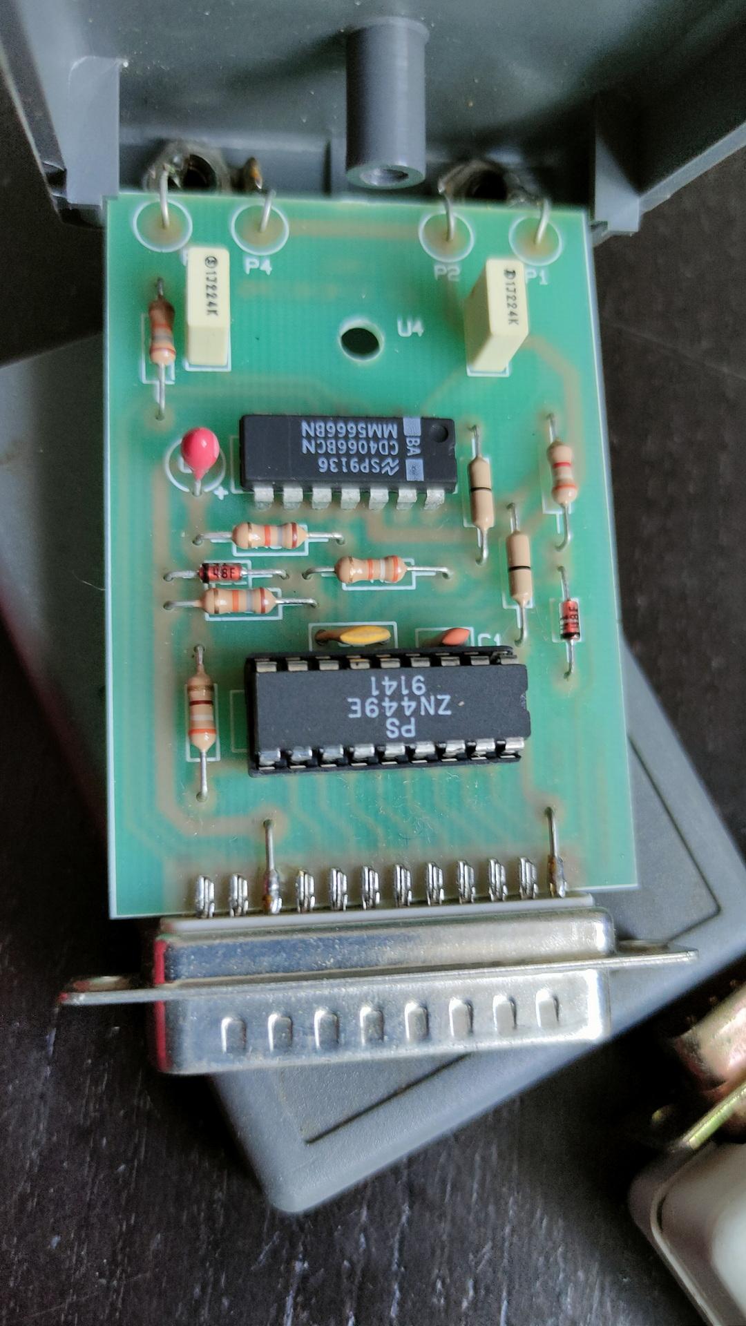
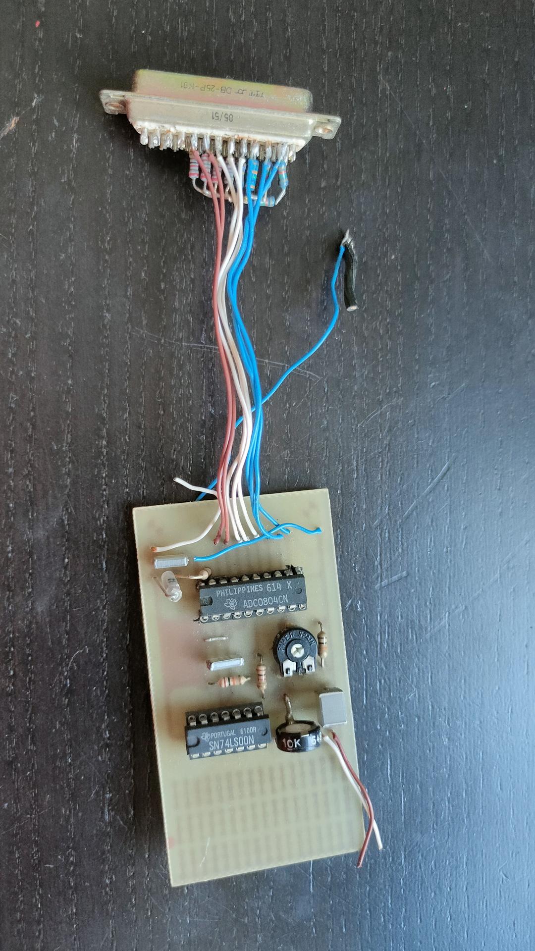
Testing the sampler (demo for Tyrone)
Sampling the sound of a C64 on an Amiga.
Started (booted) the sampling program from second external drive using switch setup as above.