yes, again. Another change.
UPDATE: Working example at bottom!
I don’t want IDs and Paths in a Home Assistant automation.
The RFIDs can store more than enough data to store the paths to albums.
I Also tested with ESPHOME in HA, but you can’t write tags.
ESPHOME Config for my RFID device (NOT USED ANYMORE)
esphome:
  name: rfidtag
  friendly_name: rfidtag

esp8266:
  board: d1_mini

mqtt:
  broker: IPMQTTBROKER

# Enable logging
logger:

# Enable Home Assistant API
api:
  encryption:
    key: "xxxxxxxxxxxxxxxxxx="

ota:
  password: "xxxxxxxxxxxxxxxxxxxxx"

wifi:
  ssid: !secret wifi_ssid
  password: !secret wifi_password

  # Enable fallback hotspot (captive portal) in case wifi connection fails
  ap:
    ssid: "Rfidtag Fallback Hotspot"
    password: "xxxxxxxxxxxxxx"

captive_portal:

spi:
  clk_pin: D5
  miso_pin: D6
  mosi_pin: D7
rc522_spi:
  cs_pin: D8
  update_interval: 1s
  on_tag:
    then:
      - mqtt.publish:
          topic: rc522/tag
          payload: !lambda 'return x;'
  on_tag_removed:
    then:
      - mqtt.publish:
          topic: rc522/tag_removed
          payload: !lambda 'return x;'
The next iteration of my Rfid controller will have a write function for the RFID tags.
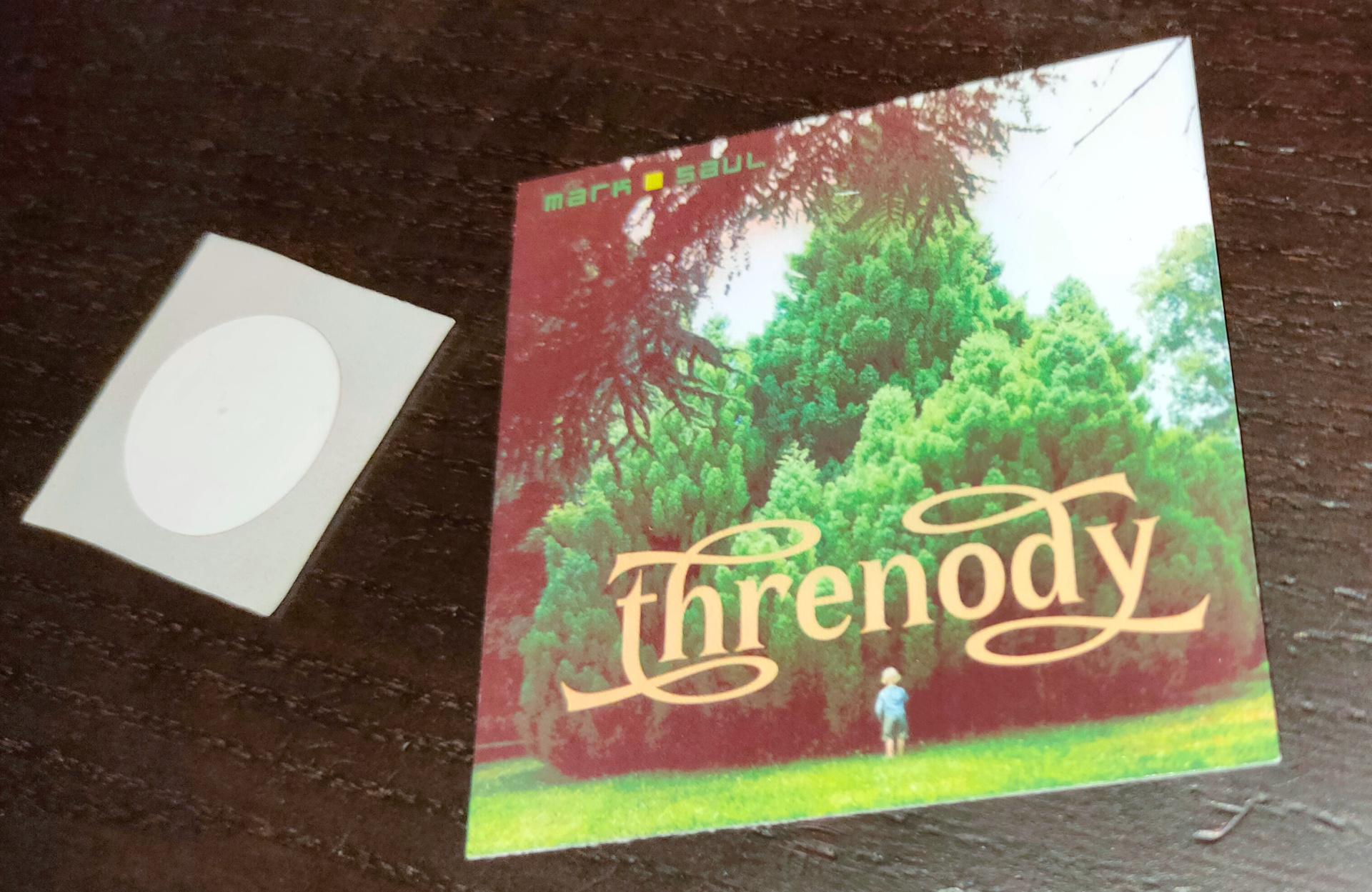
- Stick a tag on a cover art piece of cardboard. (see below)
- Read path from data sector.
- Send path to player automation
- Send path to program using MQTT or website if needed.
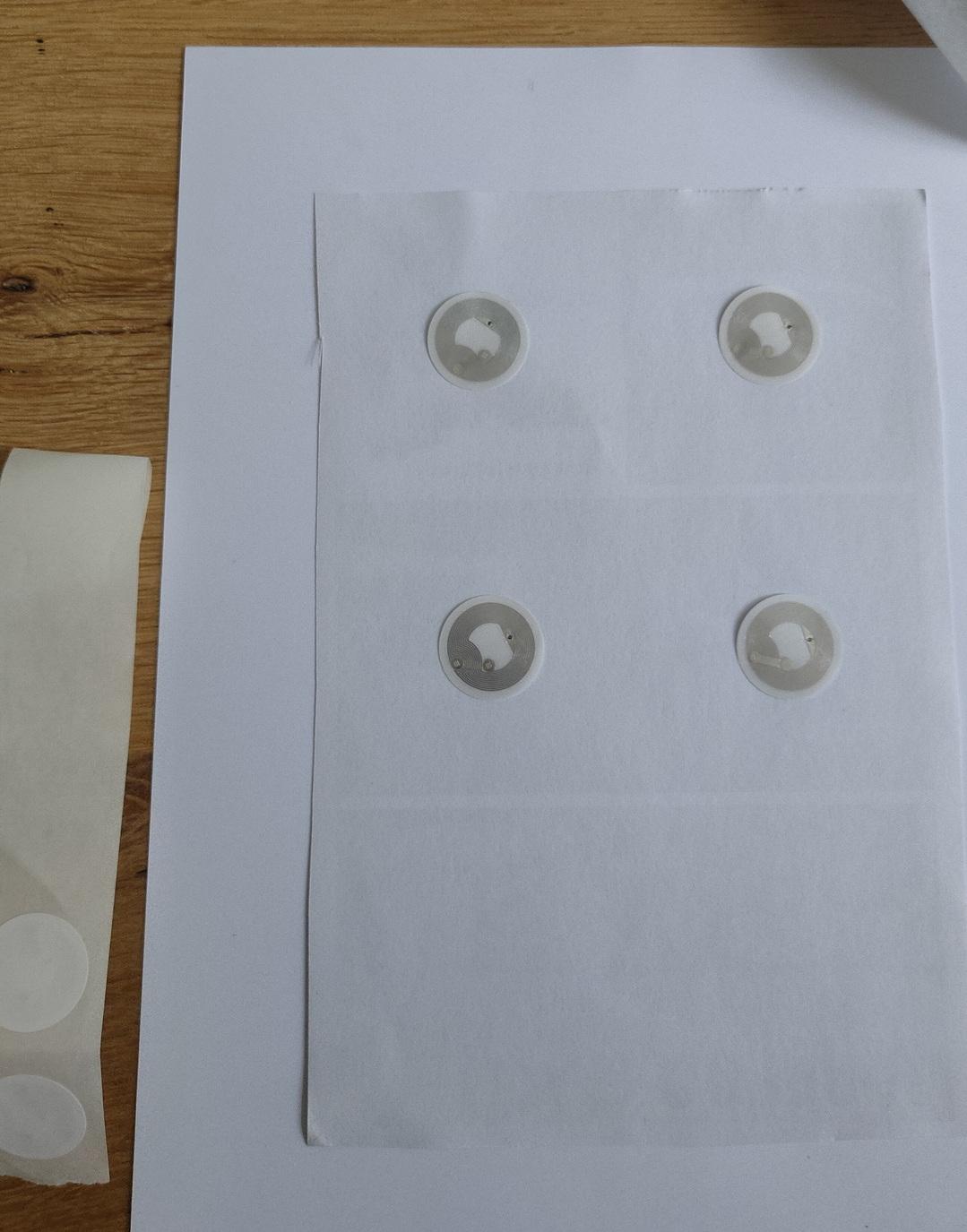
Not sure yet, also want to implement a wifi manager on the wemos.
Changes on above idea:
- Paths are too long, I could not work out how to create a working program using this.
- I stopped using paths, instead I’m using the Logitech media server album IDs.
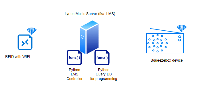
- Using two python scripts, I can use one for programming the card, and another script to control LMS.
How does it work
RFid device is connected to the network.
Start query.py on your LMS server.
Search for an album name, it will present an ID and Album name in a list.
Enter the ID you want to program, or 0 to exit.
(This will also reset the programming mode)
Place an empty or previously programmed tag on the device.
It will write the album ID on the tag.
Then it will start the album.
Changing the tags will also just change the album playing.
(NOTE: My genre spotify player still works using this method, using the same device)
A second python script will read the Mqtt topic and control the Squeezebox player.
Python Code DB Query
import sqlite3
#paho-mqtt
import paho.mqtt.publish as publish

host = "IPMQTTBROKER"
port = 1883
topic = "spotify/rfid/in/write"
auth = {'username': 'xxxx','password': 'xxxxx'}
client_id = "spotithing"

def readSqliteTable(albumname):
    try:
        sqliteConnection = sqlite3.connect('/var/lib/squeezeboxserver/cache/library.db')
        cursor = sqliteConnection.cursor()
        albumname = "%" + albumname + "%"
        cursor.execute("select * from albums where title Like ?",
               (albumname,))
        records = cursor.fetchall()
        for row in records:
            print("Id: ", row[0],row[1])
        cursor.close()

    except sqlite3.Error as error:
        print("Failed to read data from sqlite table", error)
    finally:
        if sqliteConnection:
            sqliteConnection.close()

album = input("Album name ? ")
readSqliteTable(album)

number = input("Enter ID or 0 to quit : ")
publish.single(topic, "00000" , qos=1, hostname=host, port=port,
        auth=auth, client_id=client_id)
if number == 0:
        exit()
publish.single(topic, number, qos=1, hostname=host, port=port,
        auth=auth, client_id=client_id)
print("Program your tag")
print("Reset/disable writing using exit with 0!")
Python Code Controller (this one needs to be running at all times)
import paho.mqtt.client as mqtt
import urllib.request

def on_connect(client, userdata, flags, rc):
        print("Connected with result code {0}".format(str(rc)))
        client.subscribe("spotify/rfid/idlms")

def on_message(client, userdata, msg):
        print("Message received-> " + msg.topic + " " + str(msg.payload))  # Print a received msg
        urllib.request.urlopen("http://IPADDRESLMS:9000/anyurl?p0=playlistcontrol&p1=album_id:" + msg.payload.decode() + "&p2=cmd:load&player=b8:27:eb:11:16:ab")
#NOTE also change b8:27:eb:11:16:ab into you players MACAddress!

client = mqtt.Client("digi_mqtt_test")
client.on_connect = on_connect
client.on_message = on_message
client.connect('IPMQTTBROKER', 1883)
client.loop_forever()
Arduino Code (see schematic in other post)
#include <Arduino.h>
#include <SPI.h>
#include <MFRC522.h>
#include <ESP8266WiFi.h>
#include <WiFiClient.h>
#include <PubSubClient.h>
#define SS_PIN 15
#define RST_PIN 0
MFRC522 mfrc522(SS_PIN, RST_PIN);
  MFRC522::StatusCode status; //variable to get card status
  byte buffer[18];  //data transfer buffer (16+2 bytes data+CRC)
  byte size = sizeof(buffer);
  uint8_t pageAddr = 0x06;  //In this example we will write/read 16 bytes (page 6,7,8 and 9).
                            //Ultraligth mem = 16 pages. 4 bytes per page.
                            //Pages 0 to 4 are for special functions.
unsigned long cardId = 0;
WiFiClient net;
PubSubClient client(net);
const char* mqtt_server = "IPMQTTBROKER";
const char* ssid = "MYSSID";
const char* password = "MYSSIDPASS";
String topicStr = "";
byte buffer2[8];

boolean Rflag=false;
int r_len;
char payload[5];
byte value[5];
void setup() {
  Serial.begin(9600);
  SPI.begin();
  mfrc522.PCD_Init();
  WiFi.mode(WIFI_AP_STA);
  WiFi.begin(ssid, password);
  client.setServer(mqtt_server, 1883);
     delay(100);
    client.setCallback(callback);
      delay(100);
    client.subscribe("spotify/rfid/in/#");
}
void reconnect() {
  while (WiFi.waitForConnectResult() != WL_CONNECTED) {
  }
  while (!client.connected()) {
    String clientId = "rfid-";
    clientId += String(random(0xffff), HEX);
    if (!client.connect(clientId.c_str(), "rfidclient", "...")) {
      Serial.print("failed, rc=");
      Serial.print(client.state());
      delay(5000);
    }
  }
  client.subscribe("spotify/rfid/in/#");
}
void callback(char* topic, byte* payload, unsigned int length) {

  Serial.print(F("Called"));
   Rflag=true; //will use in main loop
   r_len=length; //will use in main loop
   Serial.print("length message received in callback= ");
   Serial.println(length);
   int j=0;
     for (j;j<length;j++) {
       buffer2[j]=payload[j];
       }
if (r_len < 3) {
  Rflag=false;
  Serial.print(F("Set false"));
}
buffer2[j]='\0'; //terminate string
}

void loop() {
    if (!client.connected()) {
    reconnect();
  }
  client.loop();
  if (!mfrc522.PICC_IsNewCardPresent()) {
    return;
  }
  if (!mfrc522.PICC_ReadCardSerial()) {
    return;
  }
if (Rflag) {
        for (int i=0; i < 4; i++) {
    //data is writen in blocks of 4 bytes (4 bytes per page)
    status = (MFRC522::StatusCode) mfrc522.MIFARE_Ultralight_Write(pageAddr+i, &buffer2[i*4], 4);
    if (status != MFRC522::STATUS_OK) {
      Serial.print(F("MIFARE_Read() failed: (W) "));
      Serial.println(mfrc522.GetStatusCodeName(status));
      return;
    }
  }
  Serial.println(F("MIFARE_Ultralight_Write() OK "));
  Serial.println();
  Rflag=false;
}
  cardId = getCardId();
  char buffer3[10];
  sprintf(buffer3, "%lu", cardId);
  client.publish("spotify/rfid/id", buffer3);
  // Read data ***************************************************
  Serial.println(F("Reading data ... "));
  //data in 4 block is readed at once.
  status = (MFRC522::StatusCode) mfrc522.MIFARE_Read(pageAddr, buffer, &size);
  if (status != MFRC522::STATUS_OK) {
    Serial.println(F("MIFARE_Read() failed: (R)"));
    Serial.println(mfrc522.GetStatusCodeName(status));
    return;
  }

  Serial.println(F("Read data: "));
  //Dump a byte array to Serial
  for (byte i = 0; i < 5; i++) {
    Serial.write(buffer[i]);
       buffer2[i]=buffer[i];
    }
  client.publish("spotify/rfid/idlms", buffer,5);
  delay(1000);
  mfrc522.PICC_HaltA();
}

unsigned long getCardId() {
  byte readCard[4];
  for (int i = 0; i < 4; i++) {
    readCard[i] = mfrc522.uid.uidByte[i];
  }
  return (unsigned long)readCard[0] << 24
    | (unsigned long)readCard[1] << 16
    | (unsigned long)readCard[2] << 8
    | (unsigned long)readCard[3];
}
