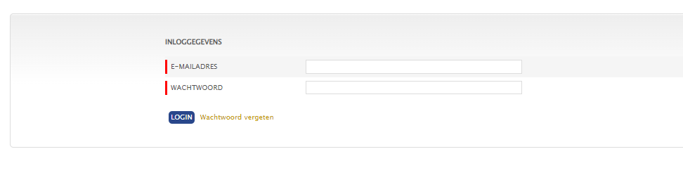
A friend needed to scrape data from an authenticated website.
This needs to be scripted and processed without human intervention.
Following steps are needed to get the correct curl commands (one time only)
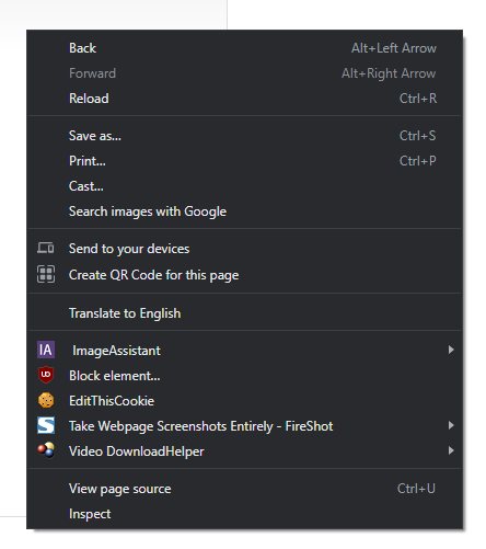
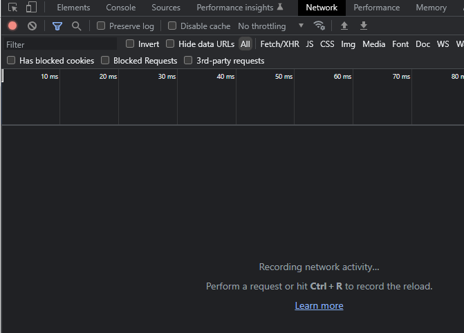
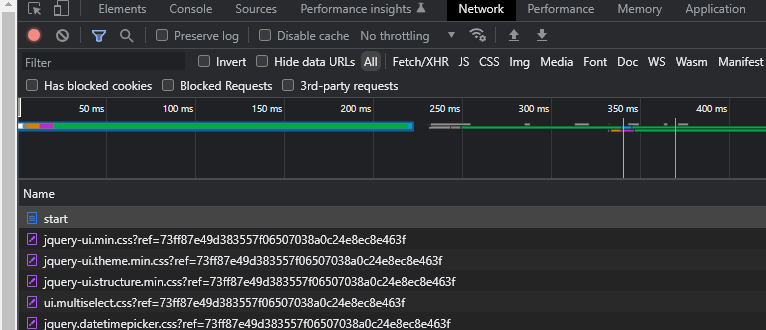
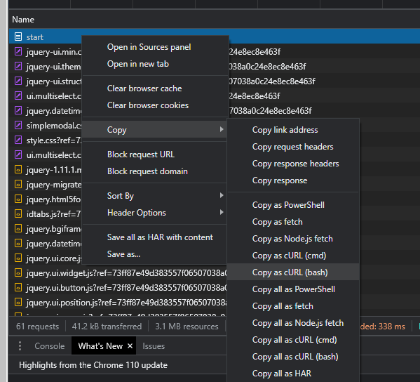
next steps
save curl command in a file
remove –compresssion and -H ‘Cookie: JSESSIONID=?????????????????????????????’
add just after curl
-k (no certificate check) and
–cookie-jar tmpcookiefile
excecute this. It will give you a file with a session id and a true field.
(This will change at every login)
but is needed for subsequential requests
Next: use this sessioncookie to get the next authenticated request
So to scrape with login, you need two lines in your script.
One to get the session cookie. (YOUR username/pass will be in here!!)
And the second to get the needed page using the cookie
#!/bin/bash
#authenticate and save sessioncookie
curl -k --cookie-jar part1.cookie 'https://xxx.xxxxx.xxx/site/dologin'   -H 'Accept: text/html,application/xhtml+xml,application/xml;q=0.9,image/avif,image/webp,image/apng,*/*;q=0.8,application/signed-exchange;v=b3;q=0.7'   -H 'Accept-Language: en-GB,en;q=0.9,nl-NL;q=0.8,nl;q=0.7'   -H 'Cache-Control: max-age=0'   -H 'Connection: keep-alive'   -H 'Content-Type: multipart/form-data; boundary=----WebKitFormBoundaryb1chvkAVZSF3hPSu'    -H 'Origin: https://xxx.xxxxx.xxx'   -H 'Referer: https://xxx.xxxxx.xxx/site/loginform'   -H 'Sec-Fetch-Dest: document'   -H 'Sec-Fetch-Mode: navigate'   -H 'Sec-Fetch-Site: same-origin'   -H 'Upgrade-Insecure-Requests: 1'   -H 'User-Agent: Mozilla/5.0 (Windows NT 10.0; Win64; x64) AppleWebKit/537.36 (KHTML, like Gecko) Chrome/110.0.0.0 Safari/537.36'   -H 'sec-ch-ua: "Chromium";v="110", "Not A(Brand";v="24", "Google Chrome";v="110"'   -H 'sec-ch-ua-mobile: ?0'   -H 'sec-ch-ua-platform: "Windows"'   --data-raw $'------WebKitFormBoundaryb1chvkAVZSF3hPSu\r\nContent-Disposition: form-data; name="form[username]"\r\n\r\nusername\r\n------WebKitFormBoundaryb1chvkAVZSF3hPSu\r\nContent-Disposition: form-data; name="form[password]"\r\n\r\npassword\r\n------WebKitFormBoundaryb1chvkAVZSF3hPSu\r\nContent-Disposition: form-data; name="form[refname]"\r\n\r\n\r\n------WebKitFormBoundaryb1chvkAVZSF3hPSu\r\nContent-Disposition: form-data; name="form[refid]"\r\n\r\n\r\n------WebKitFormBoundaryb1chvkAVZSF3hPSu\r\nContent-Disposition: form-data; name="form[refmod]"\r\n\r\n\r\n------WebKitFormBoundaryb1chvkAVZSF3hPSu\r\nContent-Disposition: form-data; name="form[csrf_hash]"\r\n\r\ncsrf_ab09f7887d9dacfe1489b68b64fe6a01\r\n------WebKitFormBoundaryb1chvkAVZSF3hPSu--\r\n'
#get data from second page
curl -k -l --cookie part1.cookie  https://xxx.xxxxx.xxx/subscriber/overview