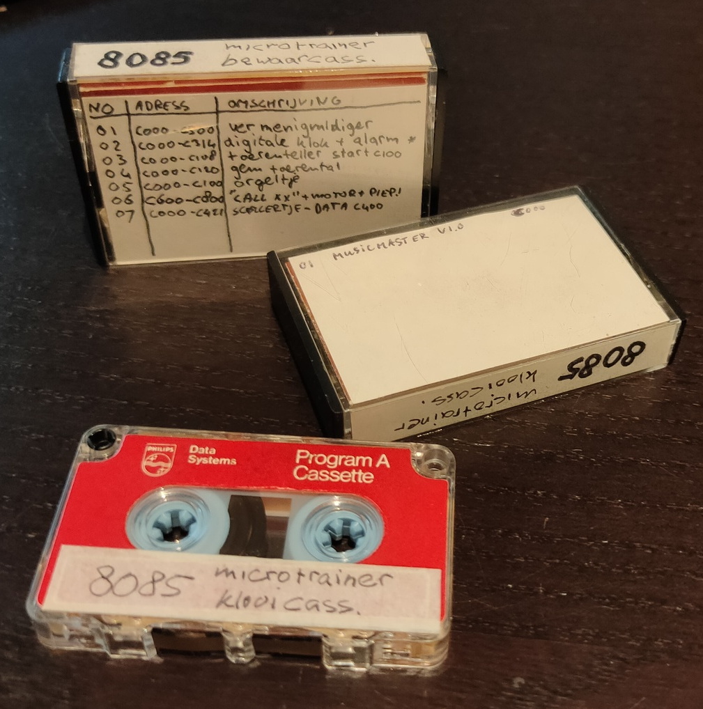
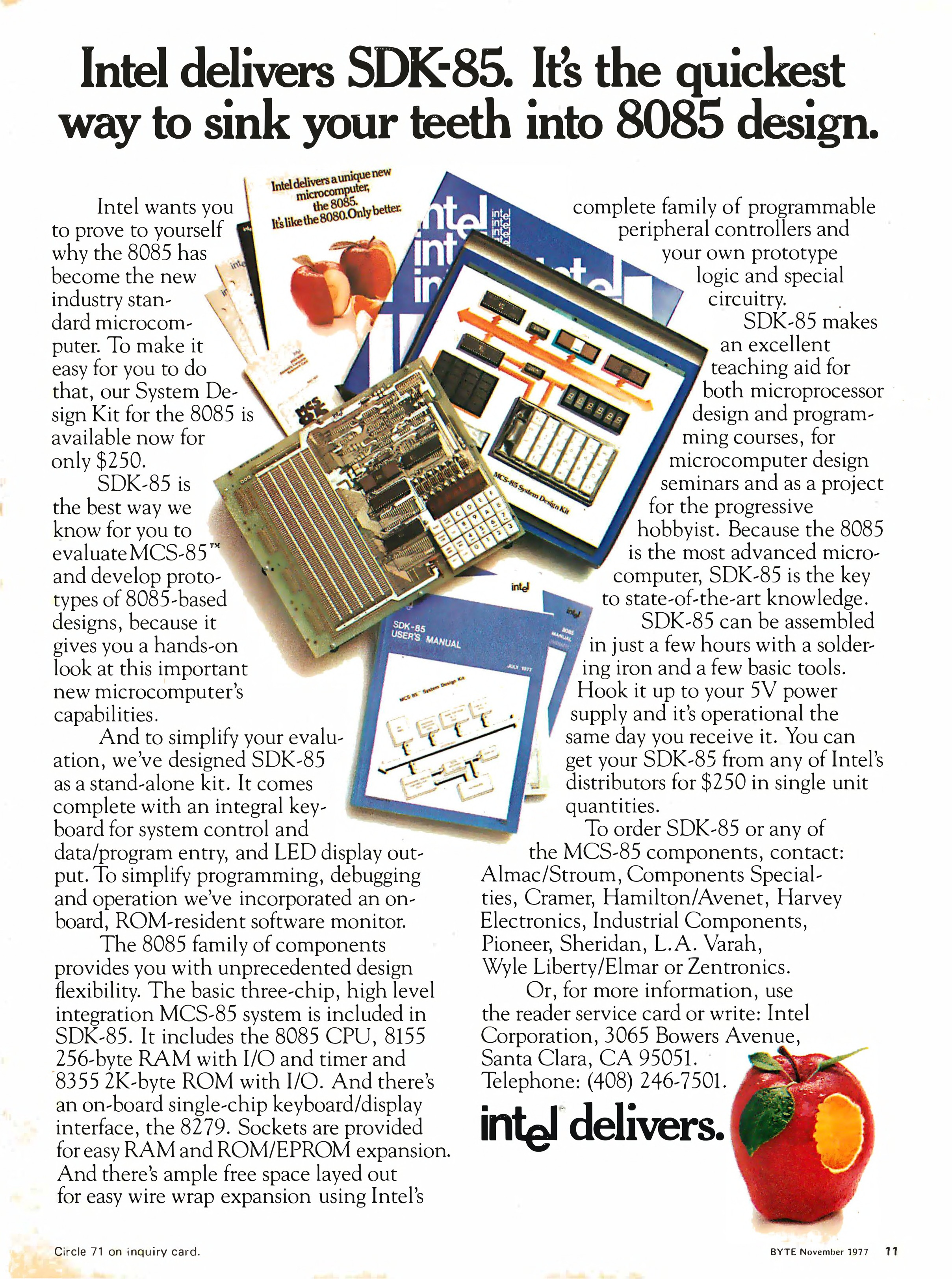
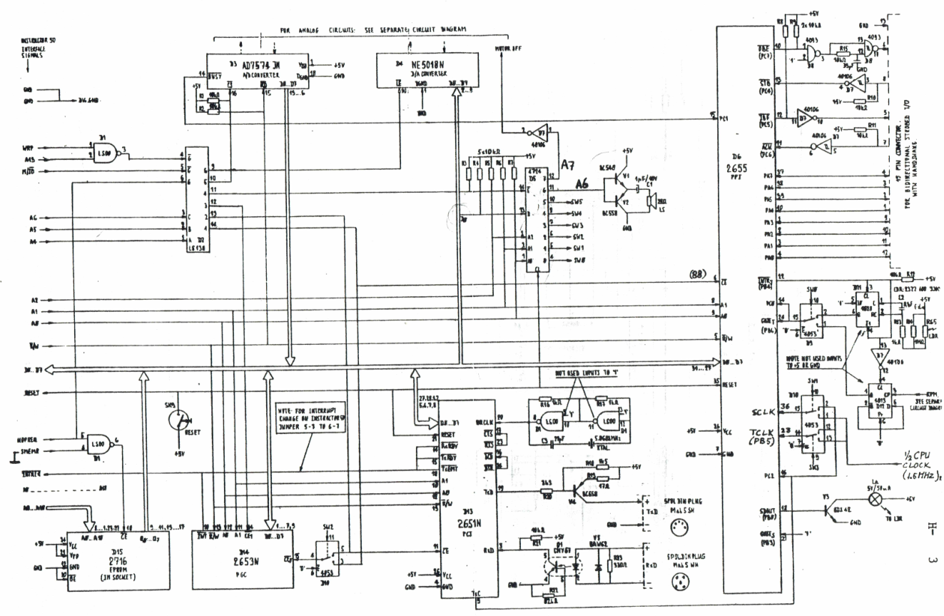
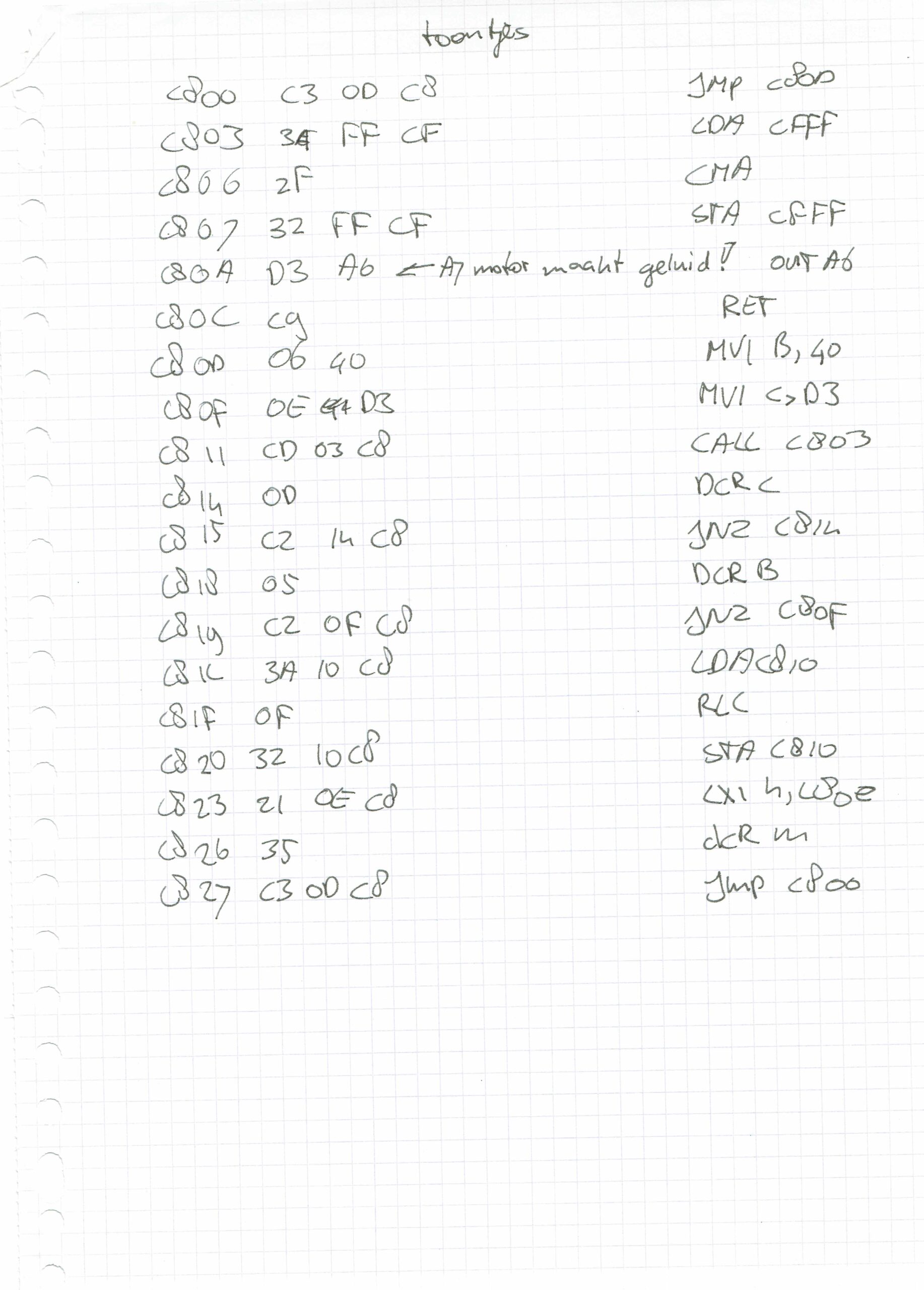
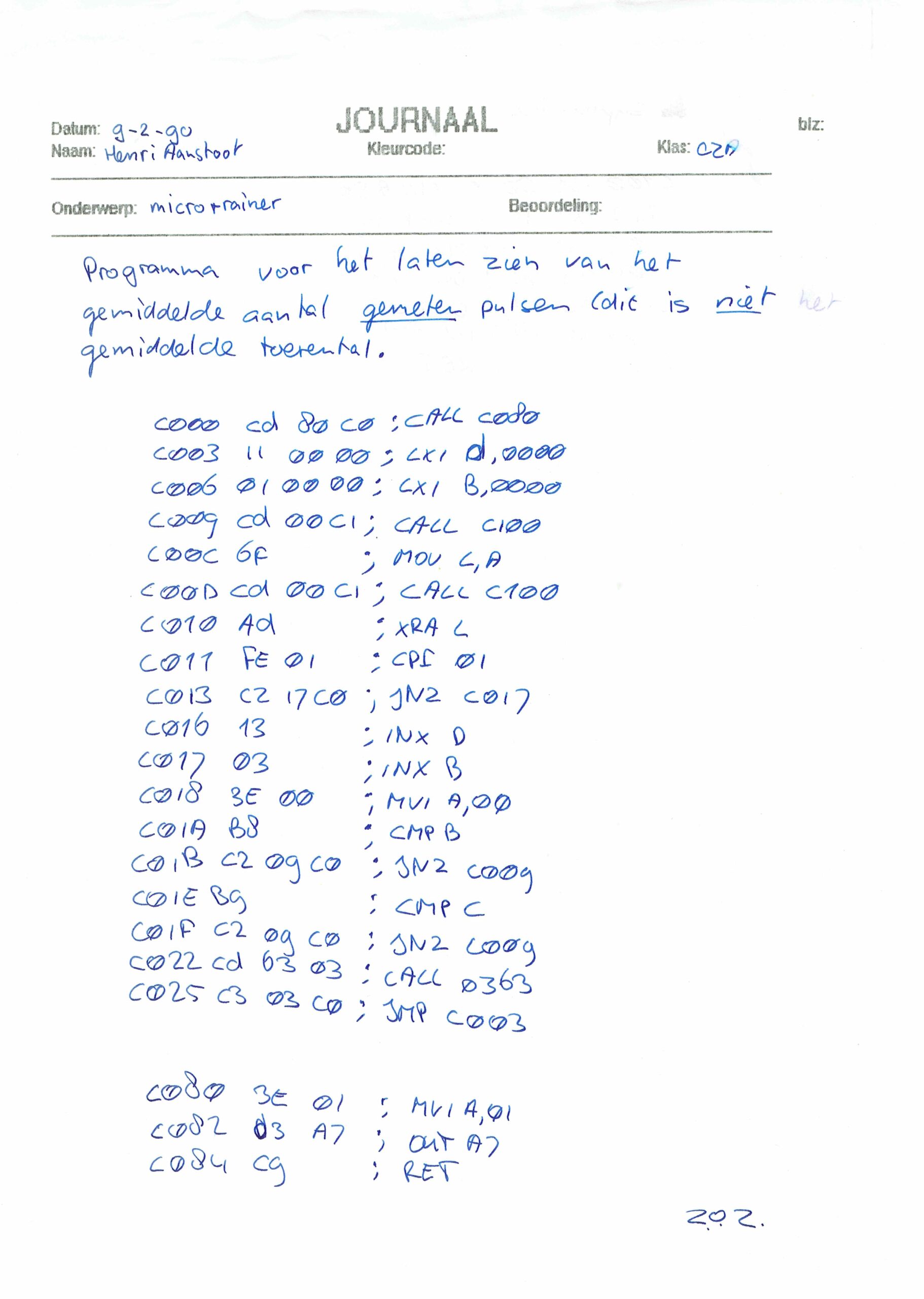
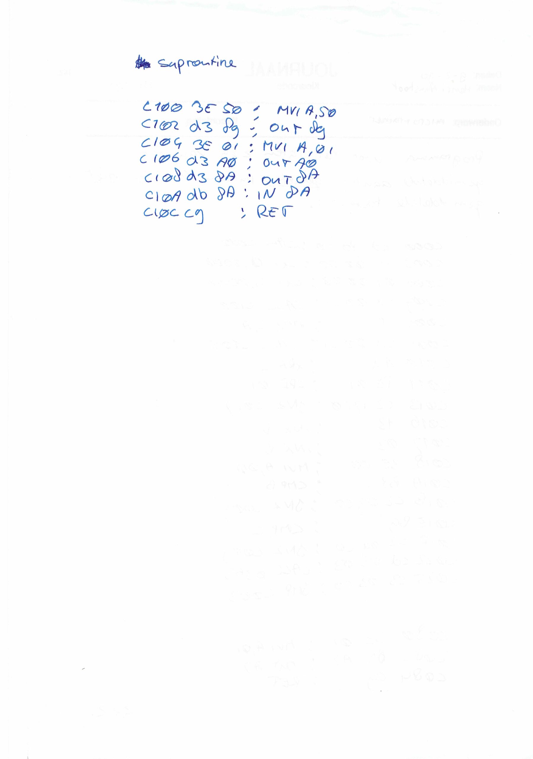
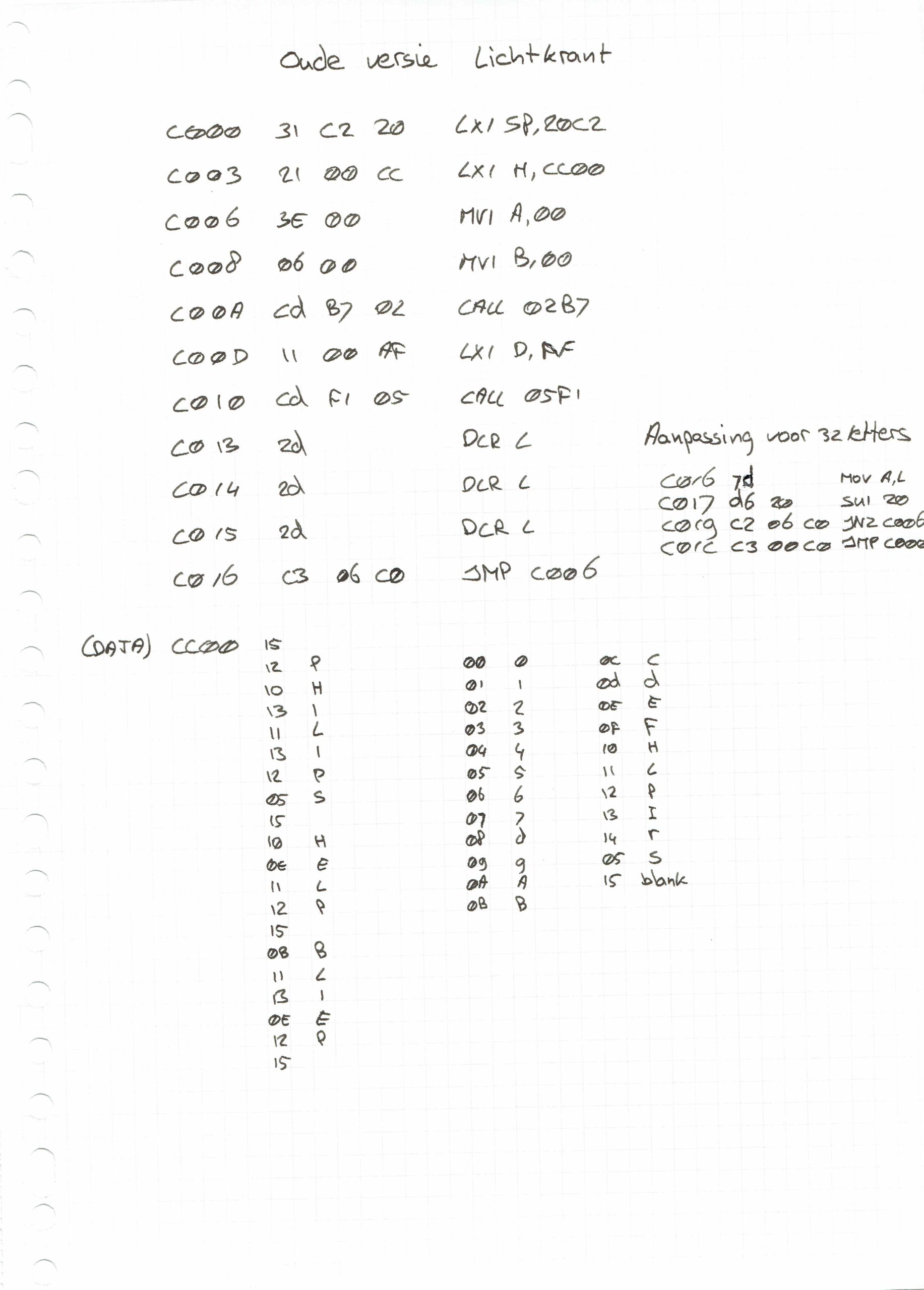
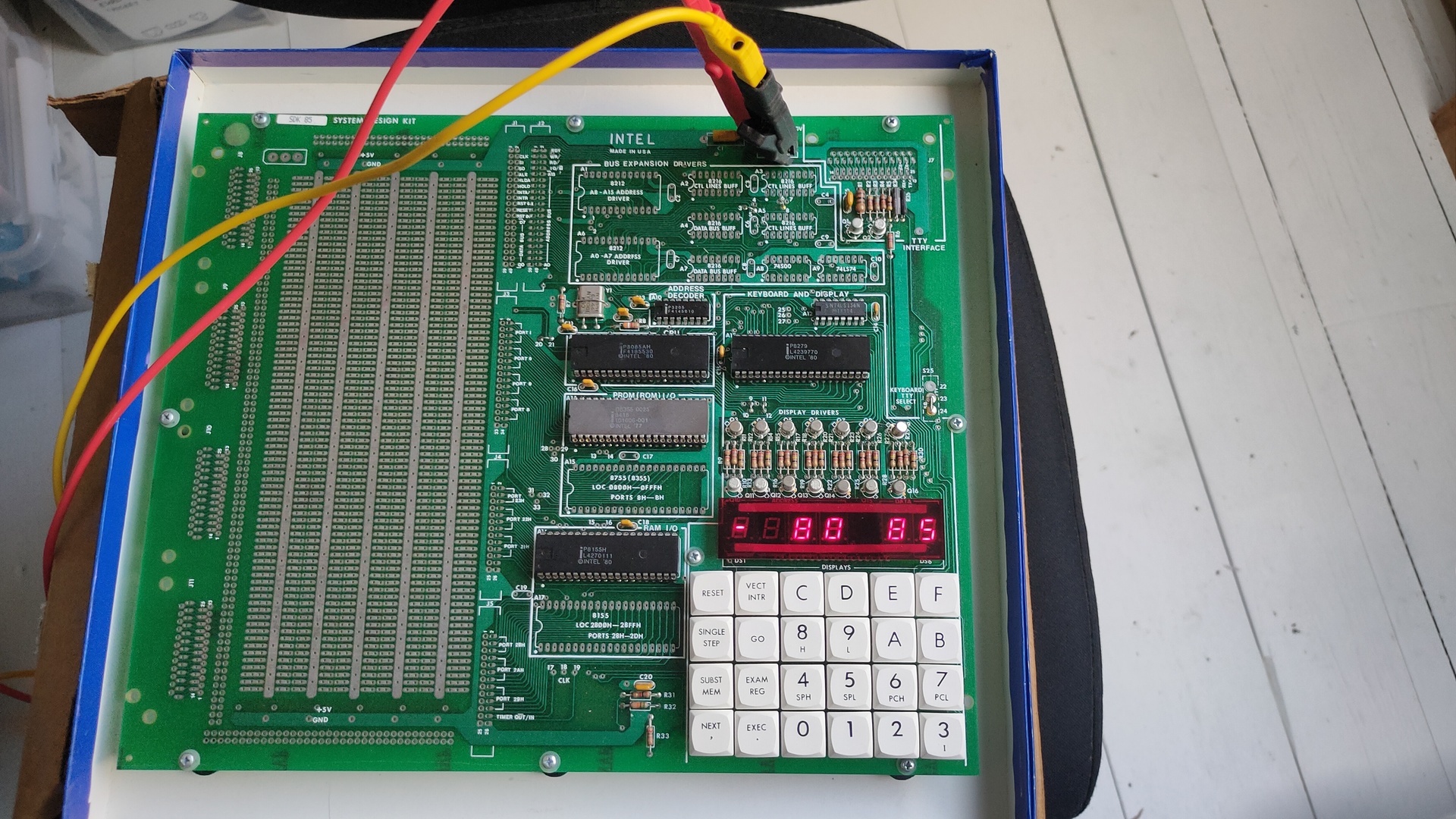
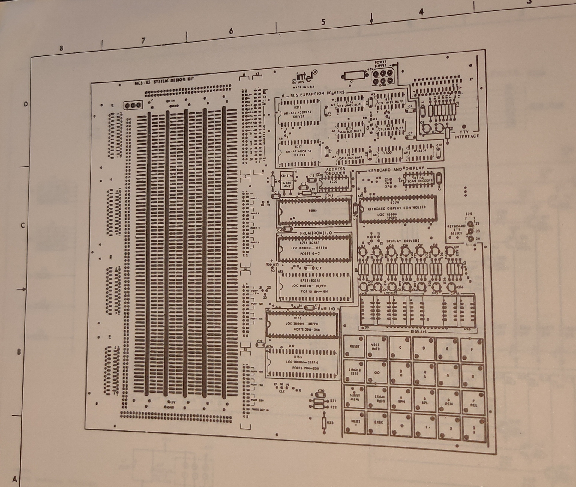
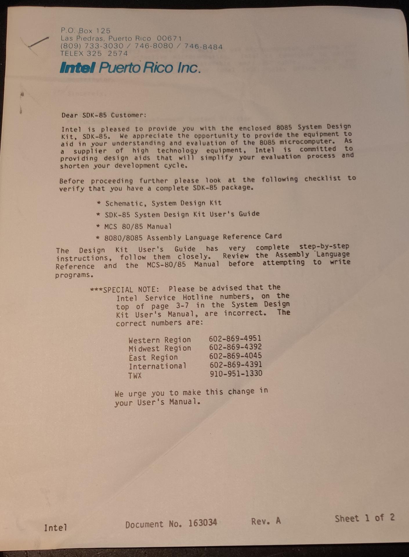
Found these old .. old mini-cassettes .. wish i could read these now. The sdk units we had, had tapedrives and few other hardware devices you could play with. Like a motor you could control, which had a disc with slots in it on top. These slots could be read and counted with a sensor to determine the speed.
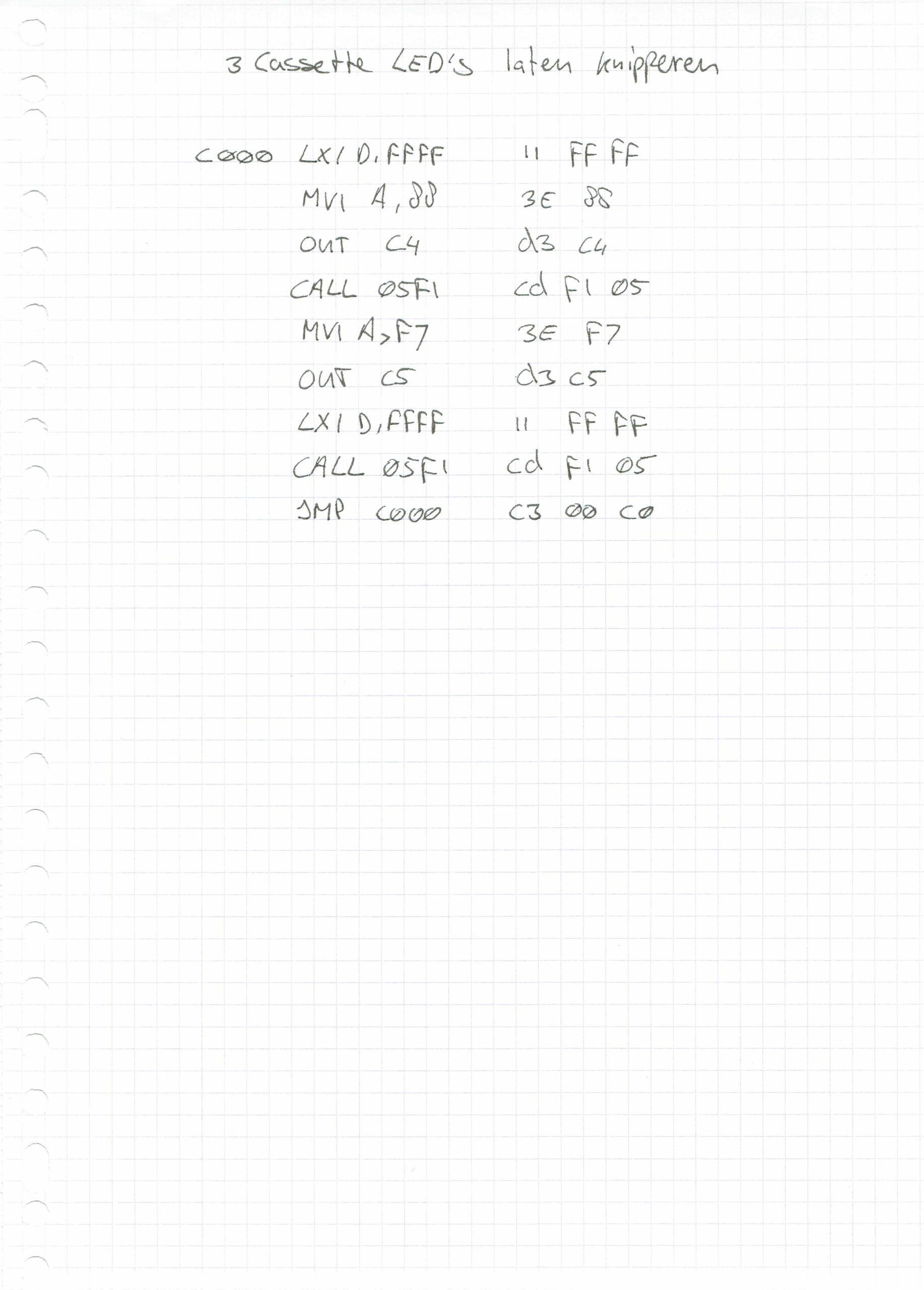
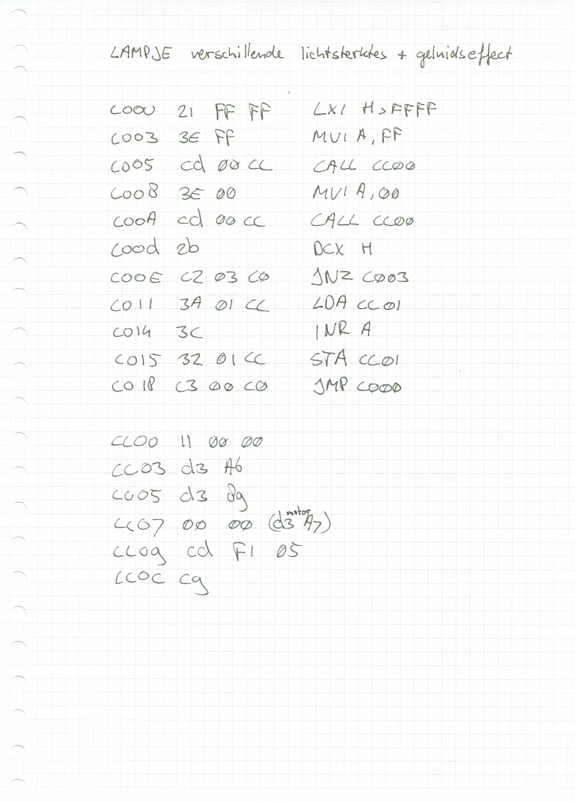
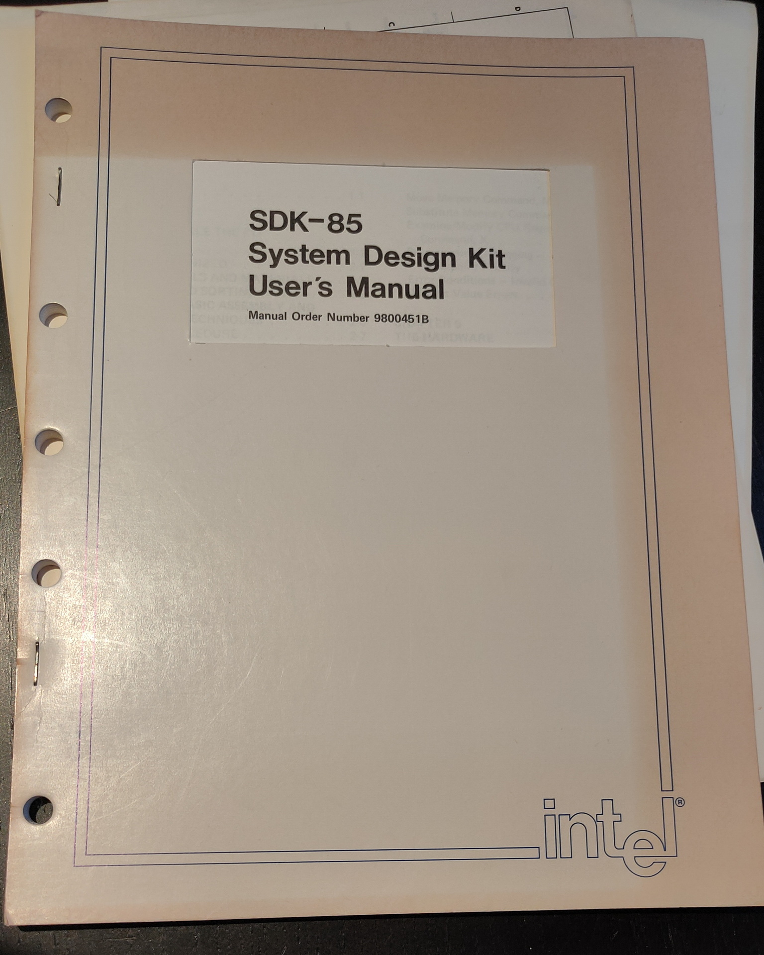
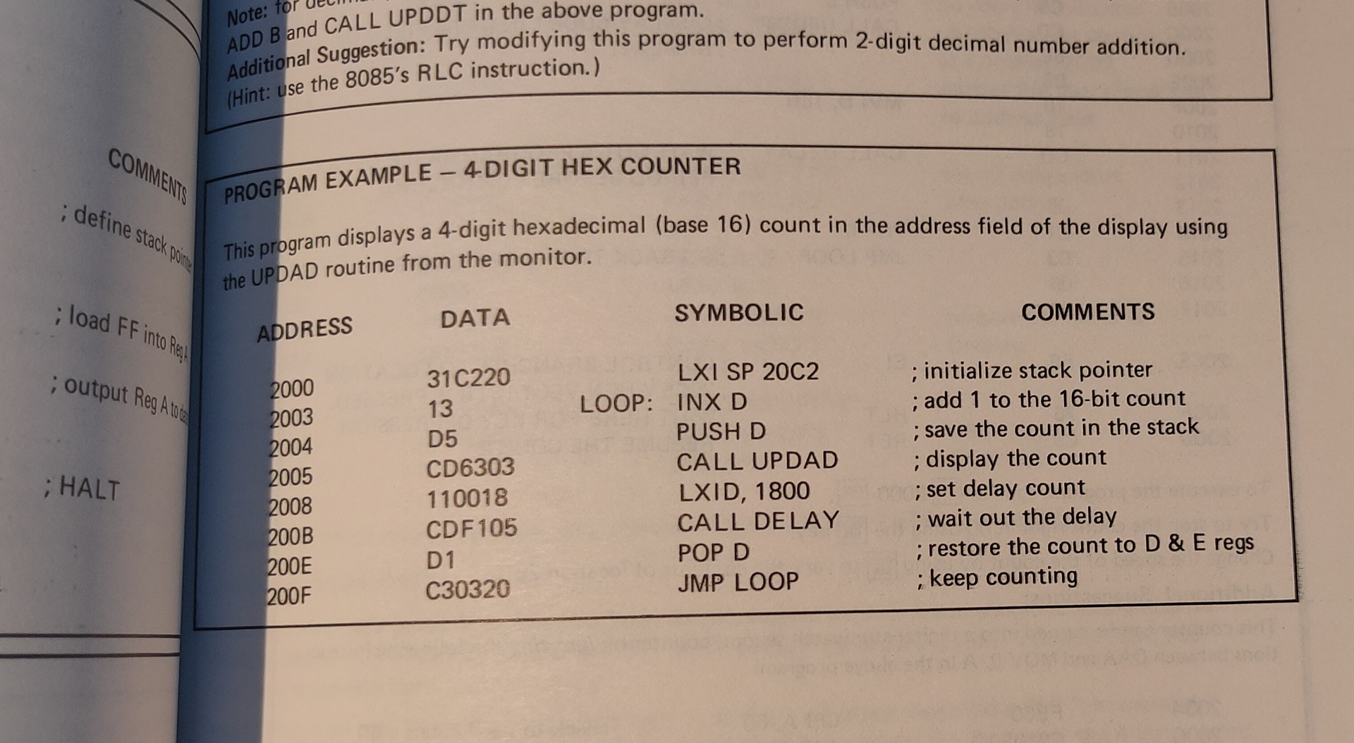
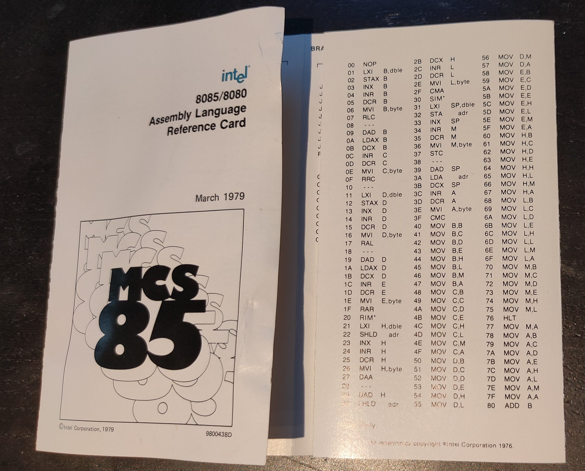
Also this scanned pages, from school i found. There should also be a little notbook with programs and notes ..
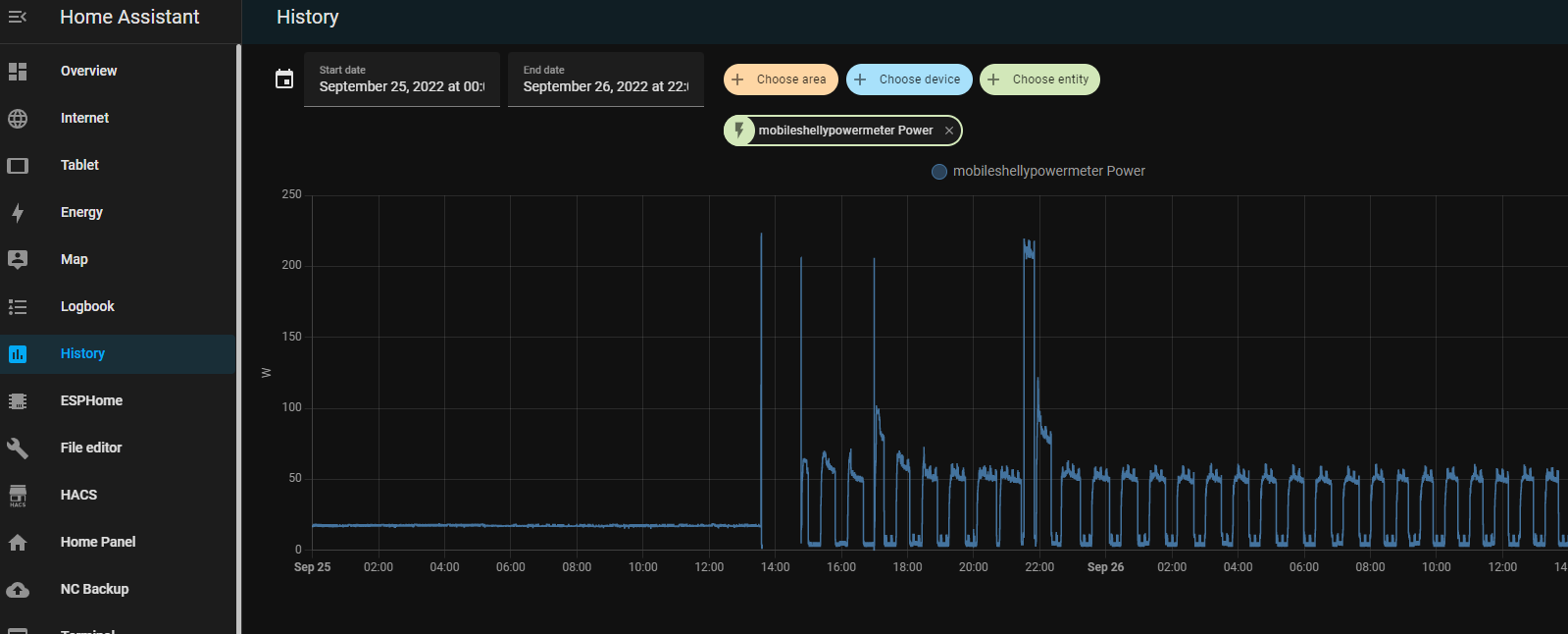
Having a lot of devices and running a Lab wil use a lot of energy. Now with the energy crisis in Europe, i had to take a closer look at whats using power in my house.
I notished some weird usage patterns while measuring.
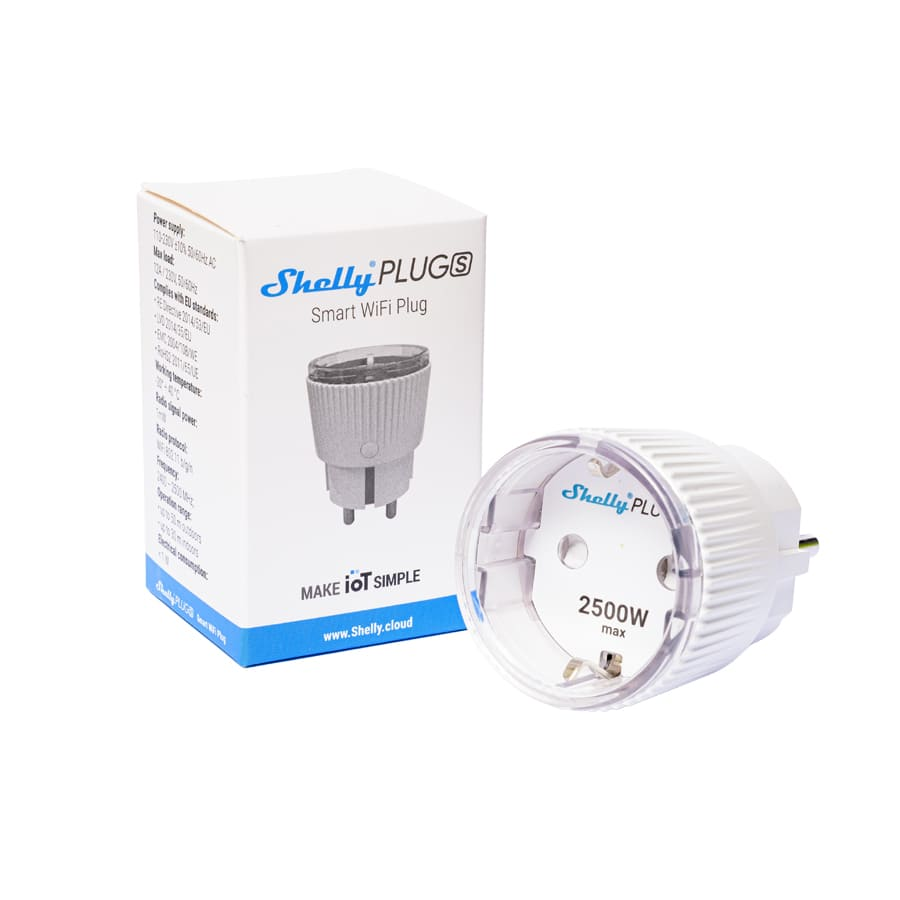
I’m using a few shelly power plugs, to measure devices and powerstrips.
With these devices you can control devices connected to it. On/Off/Timer etcetera. It wil measure the power usage in watts, and it even got a temperature sensor. I like the fact that it perfectly integrates into your home automation using an extensive API. curl commands to controll, and even MQTT messaging. Intergrating in Home Assistant is a breeze.
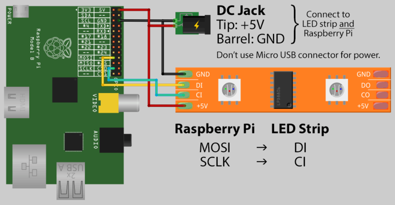
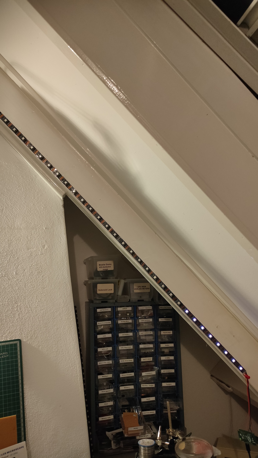
So i was monitoring a bunch of stuff using Nodered/Grafana/Homeassistant and saw some recurring usage. But being always late to check things, i made use of my ledserver i’ve build a long time ago.
This ledserver consists of a Raspberry Pi Zero, with a led string and a API written in python.
Below is autostarted on the Raspberry
( I made this ledserver for work, it showed the status of servers and services. Beside that every colleage had a range which he could use for his own scripts. I made some little bash script templates to have led funtions standard in your bash profile.
#!/usr/bin/python


# apt-get install python-flask
#

import Adafruit_WS2801
import Adafruit_GPIO.SPI as SPI
import struct

from flask import Flask, render_template, request
app = Flask(__name__)

PIXEL_COUNT = 32
SPI_PORT   = 0
SPI_DEVICE = 0

pixels = Adafruit_WS2801.WS2801Pixels(PIXEL_COUNT, spi=SPI.SpiDev(SPI_PORT, SPI_DEVICE))

pixels.clear()
pixels.show()

@app.route("/led/<deviceName>/<color>")
def action(deviceName, color):
        if deviceName == 'reset':
                print ("reset")
                pixels.clear()
        print (deviceName)
        led = int(deviceName)
        s = color
        r = int(s[ :2], 16)
        b = int(s[2:4], 16)
        g = int(s[4: ], 16)

        pixels.set_pixel_rgb(led, r,g,b)
        pixels.show()

        templateData = {
                'rled'  : r,
                'bled'  : b,
                'gled'  : g,
                'deviceName'  : deviceName,
        }
        return render_template('index.html', **templateData)

@app.route("/control/<controlcommand>")
def actioncommand(controlcommand):
        if controlcommand == 'clear':

                print("clear")
                pixels.clear()
                pixels.show()

        templateData = {
                'controlcommand'  : controlcommand,
        }
        return render_template('index.html', **templateData)

@app.route("/range/<start>/<stop>/<color>")
def rangecommand(start,stop,color):
        s = color
        r = int(s[ :2], 16)
        b = int(s[2:4], 16)
        g = int(s[4: ], 16)
        startled = int(start)
        stopled = int(stop)
        while (startled < stopled):
          pixels.set_pixel_rgb(startled, r,g,b)
          startled=startled + 1
        pixels.show()

        templateData = {
                'rangecommand'  : rangecommand,
        }


        return render_template('index.html', **templateData)


if __name__ == "__main__":
   app.run(host='0.0.0.0', port=8080, debug=True)
Now you can control the leds with a simple curl command:
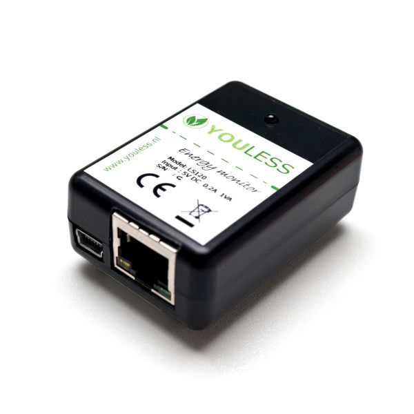
So today i made a little script to show power usage.
I’m reading the current power usage from a LS120 Youless
Youless LS120 device, which you can connect to your P1 connector.
With below bash script i’m reading the webinterface and update the ledstring. I was using this ledserver for general notification usage. Below a 2 minute hack ..
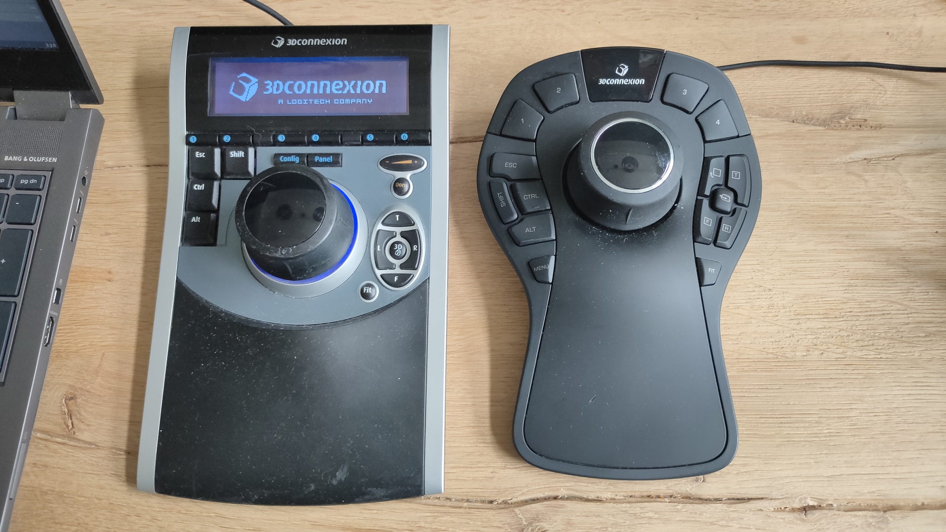
Yesterday i got two 3DConnexion 3D CAD mouses (mice) from my friend Vincent. While we where fixing his Mikrotik network i got to play with these cool devices.
I always wanted one of those, but they are quite expensive
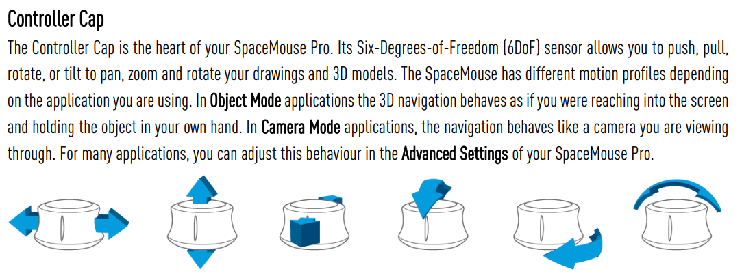
First i tried to install the Software from 3DConnexion. It kindda worked but needed some workarounds and still wasn’t okay.
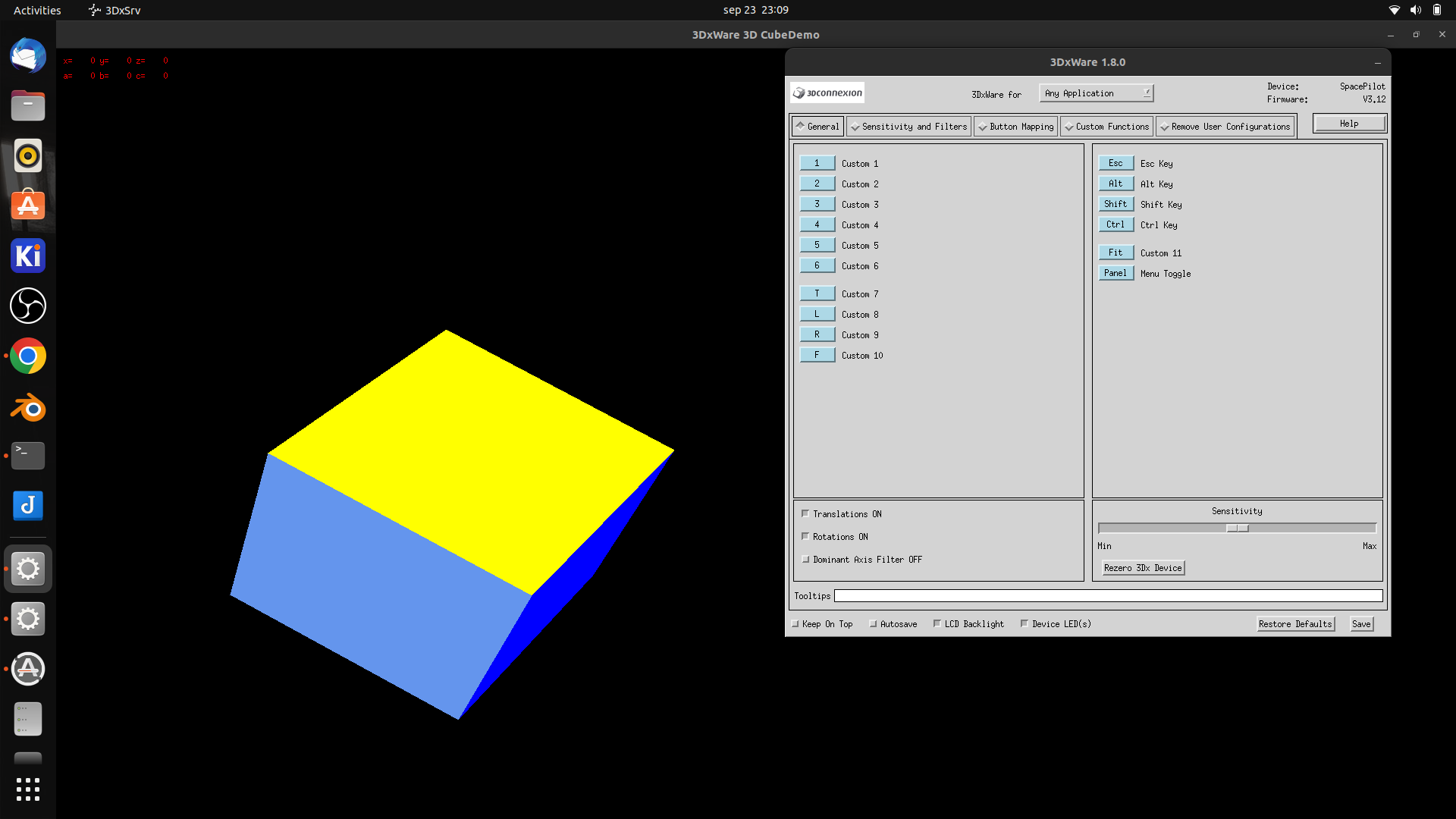
Downloaded 3dxware-linux-v1-8-0.x86_64.tar.gz (Maybe this version is TOO new, SpacePilot i a little ouder)
there is a install-3dxunix.sh, but it was made for Suse/Redhat

This program needed motif .. and a lot of libraries (libmotif/libxm)
After that some fonts xfonts-100dpi xfonts-75dpi


workaround was starting by
sudo /etc/3DxWare/daemon/3dxsvr -userName ${USER} -d usb
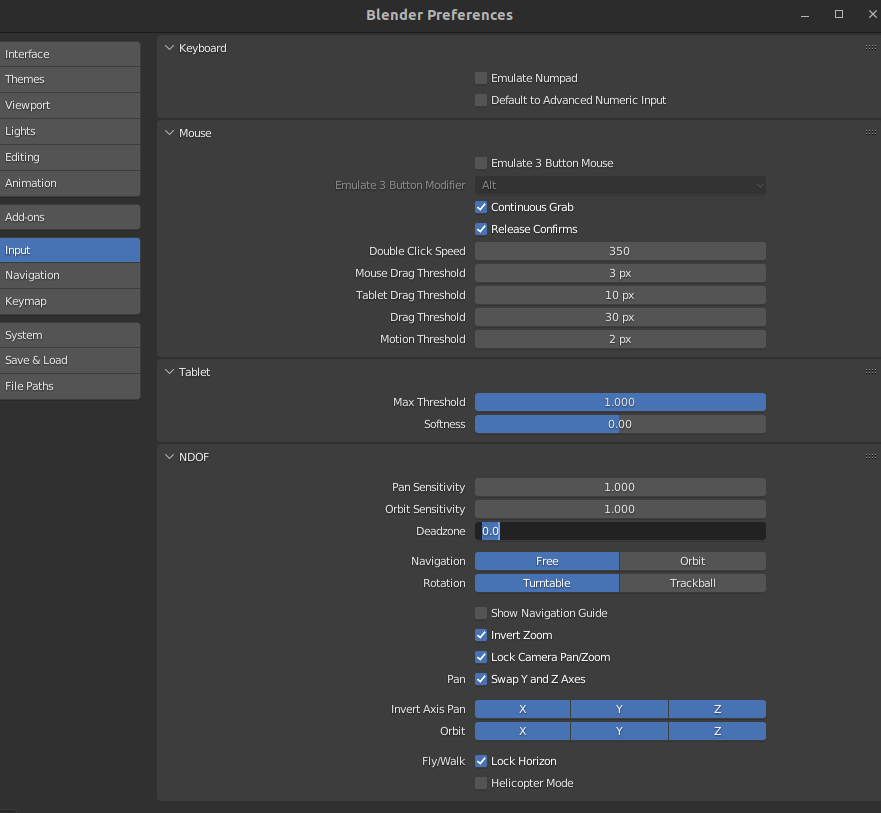
After that the demo program worked perfectly … but Blender didn’t After some tinkering it work a little, it was far to sensitive, and was all over the place.
Luckily i found a opensource replacement. https://spacenav.sourceforge.net/ git cloned the package, then i notished .. there is a precompiled version for ubuntu!
apt-get install spacenavd .. start the service .. and go!
i cloned the test demos (libspnav) and compiled those test programs.
apt-get install libglu1-mesa-dev
git clone https://github.com/FreeSpacenav/libspnav.git
cd libspnav
./configure
make
... fly is a nice little test program
So lets start blender
Pan tilt roll .. nice!
This wil speedup modeling, and for sure sculpting !
Some settings which worked for me .. let the tweaking begin!
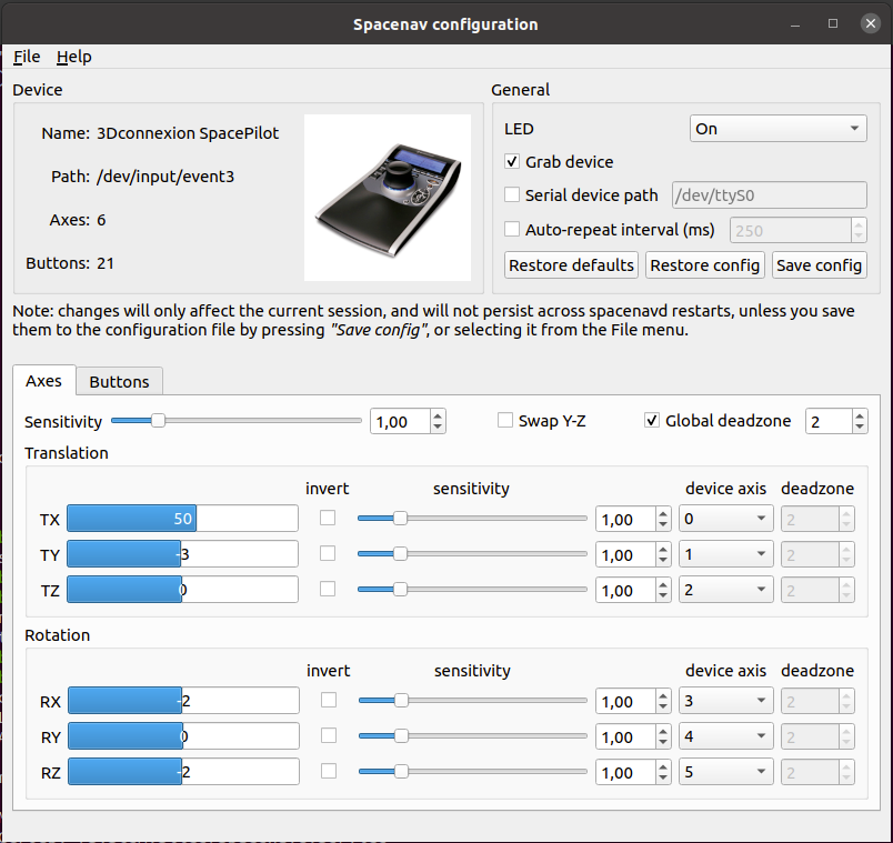
UPDATE: 2022-09-29
I removed the version in the apt repository, and installed everything from git. Now i have a cool configure tool
How about a quess the picture from our photo collection?? (123580 photos .. ) So i show a random picture, and when i press ESC it will show some information about the picture … Quess the year and the event
Well i gave myself 15 minutes to program something ..
I was watching a tv show meanwhile .. but i managed to come up with this …
This script is showing a picture, when you press ESC it wil show some details.After that it will select another random picture.
Improvements : reading tags and other metadata from my photo database, to give more information.
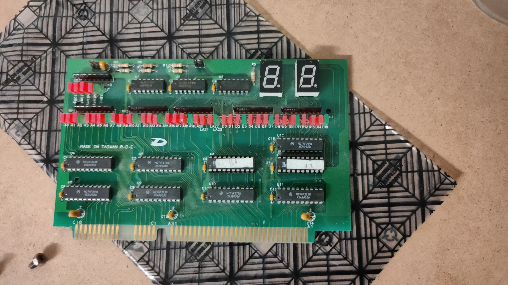
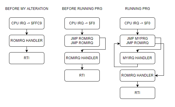
I’ve got a ROM in my 6502 which can load programs at $0200. When running own programs i want to use IRQ’s, but my rom is also using IRQ routines. So i was wondering if i could ‘hijack’ this IRQ for own program purposes.
So i’ve altered the rom to use a vector in userspace.
CPU starts, getting vector from FFFC
Goto $8000 main ROM program
Setting a jmp routine on zero page $F0
4C C9 FF
4C C9 FF ; second time, first one will redirect
Running my program on $0200
Change first jmp C9 FF to my own IRQ part
Changed jmp vectors
4C 6E 02 ; jmp $026E (myprg)
4C C9 FF ; jmp $FFC9 (rom)
Run rest of program
All seems fine and dandy … buzzer is sounding, but no blinky leds. When flashing the rom with only my program, everything works .. So whats going on? .. anyone?
MYIRQ = $F0                                     ; Own IRQ vector <=================== my additions/alterations

; Below definitions for VIA 1 my loadable program uses VIA 2
PORTB = $6000                                   ; VIA port B
PORTA = $6001                                   ; VIA port A
DDRB = $6002                                    ; Data Direction Register B
DDRA = $6003                                    ; Data Direction Register A

-------------8<------- snip

PROGRAM_LOCATION = $0200                        ; memory location for user programs

    .org $8000

main:                                           ; boot routine, first thing loaded
    ldx #$ff                                    ; initialize the stackpointer with 0xff
    txs

; ISR redirect code  <=================== my additions/alterations
    sei
    lda #$4C
    sta MYIRQ
    sta MYIRQ + 3
    lda #<ISR
    sta MYIRQ + 1
    sta MYIRQ + 4
    lda #>ISR
    sta MYIRQ + 2
    sta MYIRQ + 5
    cli

; End ISR redirect <=================== till here

; below this the standard rom routines

-------------8<------- snip
    .org $FFC9                                  ; as close as possible to the ROM's end

ISR:                                                  <====================== Whole ISR not my code
CURRENT_RAM_ADDRESS = Z0                        ; a RAM address handle for indirect writing
    pha
    tya
    pha
    lda ISR_FIRST_RUN                           ; check whether we are called for the first time
    bne .write_data                             ; if not, just continue writing
    lda #1                                      ; otherwise set the first time marker
    sta ISR_FIRST_RUN                           ; and return from the interrupt
    jmp .doneisr
.write_data:
    lda #$01                                    ; progressing state of loading operation
    sta LOADING_STATE                           ; so program_ram routine knows, data's still flowing
    lda PORTB                                   ; load serial data byte
    ldy #0
    sta (CURRENT_RAM_ADDRESS),Y                 ; store byte at current RAM location
                                                ; increase the 16bit RAM location
    inc CURRENT_RAM_ADDRESS_L
    bne .doneisr
    inc CURRENT_RAM_ADDRESS_H
.doneisr
    pla                                         ; restore Y
    tay
    pla                                         ; restore A
    rti

    .org $fffc
    .word main                                  ; Main ROM program
    .word MYIRQ                                 ; Redirect to OWN irq vector <=================== my additions/alterations
RAM Program
; Second VIA stuff
PORTB = $5000
PORTA = $5001
DDRB = $5002
DDRA = $5003
;------------------8<-------------

; Vector pointer on zero page
MYIRQ = $F0

ticks = $00 ; 4 Bytes
toggle_time = $04 ; 1 Byte

    .org $0200

start:
; IRQ REDIRECT
    sei               ; irq masked
    lda #<irq         ; get low byte IRQ routine address
    sta MYIRQ + 1     ; store at $F1

    lda #>irq         ; get high part of address
    sta MYIRQ + 2     ; store at $F2
    cli               ; irq enabled
; IRQ END REDIRECT

; init of program part
    lda #%11111111
    sta DDRA
    sta DDRB
        lda #$00
    sta PORTA
    sta PORTB
    sta toggle_time
    jsr init_timer
    lda #$77
    sta T1CL
    lda #$07
    sta T1CH

loop:                       ; loop
    jsr update_led          ; update led routine
    jmp loop

update_led:
    sec
    lda ticks
    sbc toggle_time
    cmp #25
    bcc exit_update_led
    ; Toggle led
    lda #%01000000
    eor PORTB
    sta PORTB
    lda ticks
    sta toggle_time
exit_update_led:
    rts

;-----------------------------8<------------- snip

irq:
    pha
    lda #$0e
    sta T2CL
    lda #$27
    sta T2CH
    inc ticks
    bne end_irq
    inc ticks + 1
    bne end_irq
    inc ticks + 2
    bne end_irq
    inc ticks + 3
end_irq:
    pla
    jmp MYIRQ + 3           ; jmp to vector which points to ROM routine ; should be $FFC9
Buzzer and led on VIA 2, blinky and sound timed by the internal timers of the 6522
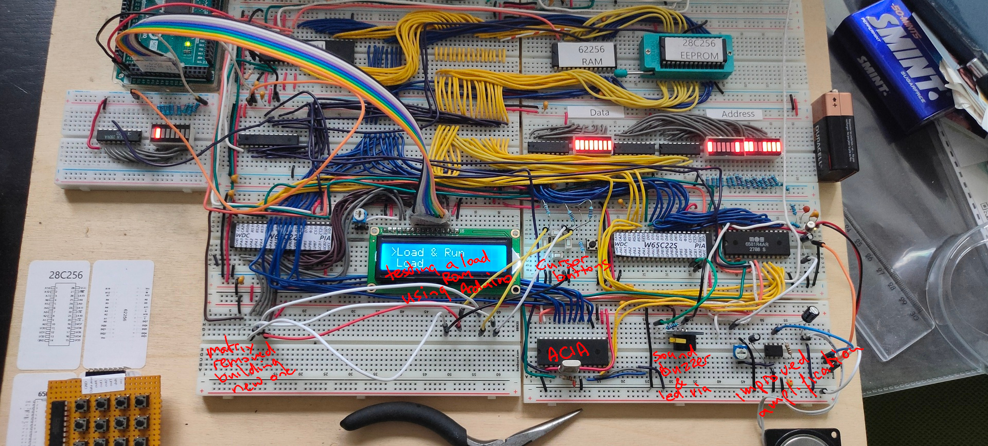
ACIA testing still going on, writing software
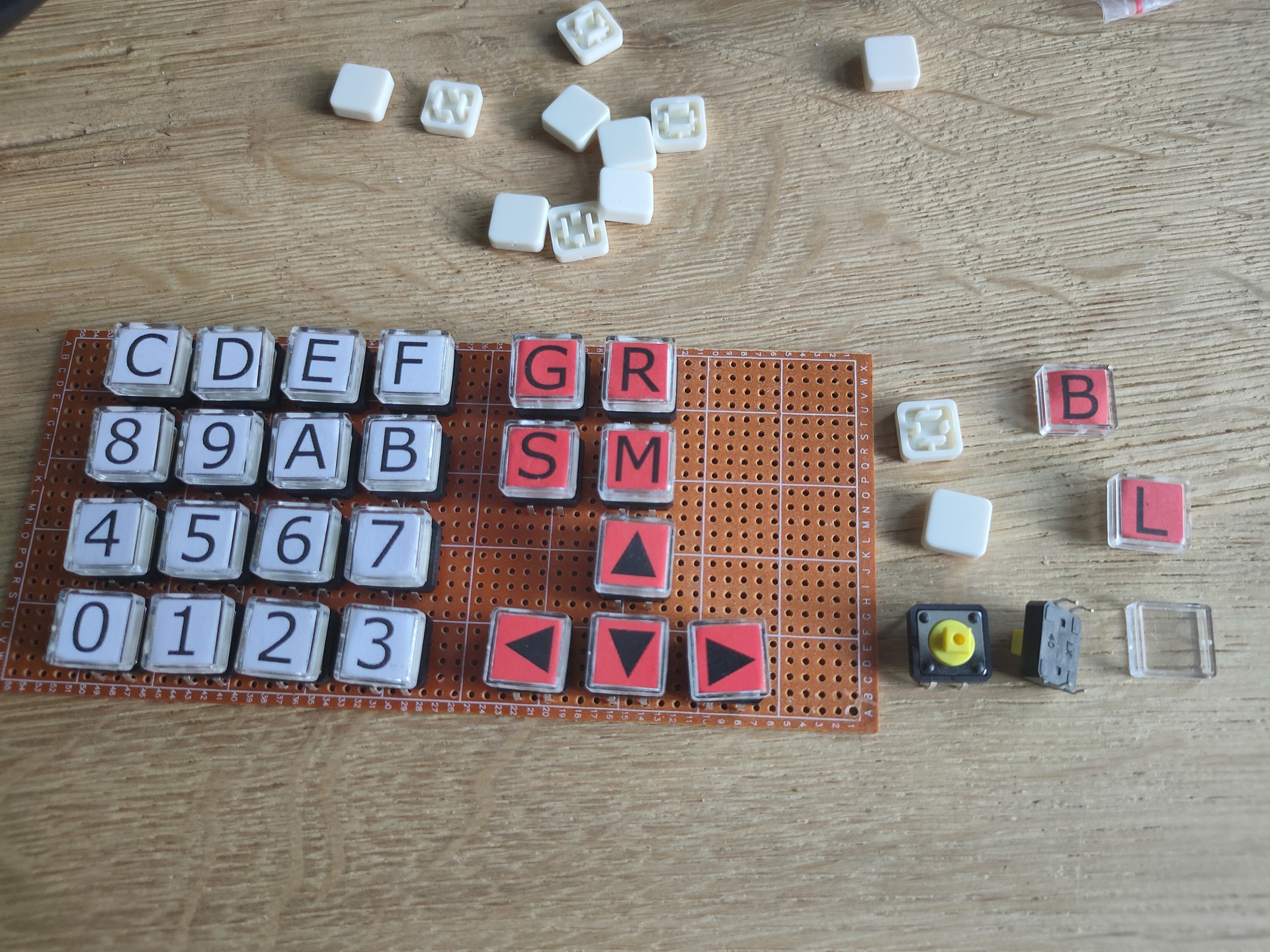
Mini matrix keyboard removed, and used the temporary cursor buttons for the test with a rom which allows for a 8bits upload method using a arduino and the 6522. (I’m working on the big keyboard)
Work in progress code
PORT2B = $5000 		; VIA PORTB
PORT2A = $5001 		; VIA PORTA
DDR2B = $5002  		; Data direction register
DDR2A = $5003  		; Data direction register

PORTB = $6000 		; display
PORTA = $6001 		; control display + matrix keyboard
DDRB = $6002  		; data direction register
DDRA = $6003  		; data direction register
SID = $7000   		; sid base address

E  = %10000000		; enable bit
RW = %01000000		; RW bit
RS = %00100000		; Register Select bit
HOME = %00000010 	; VIA PORTB HOME command
DADDR = %00010000 	; VIA DADDRESS

LINENO = $0200		; temp address linenumber (move to other location)
NEXTLINE = 40		; 2x16 Chars but internally 40


  .org $8000

reset:
  ldx #$ff
  txs		; reset stack

; ###################################################
; #                 DISPLAY CONTROL                 #
; ###################################################
; VIA Setup

  lda #%11111111 	; Set all pins on port B to output
  sta DDRB
  lda #%11100000 	; Set top 3 pins on port A to output
  sta DDRA

; DISPLAY Setup
  lda #%00111000 	; Set 8-bit mode; 2-line display; 5x8 font
  jsr lcd_instruction
  lda #%00001110 	; Display on; cursor on; blink off
  jsr lcd_instruction
  lda #%00000110 	; Increment and shift cursor; don't shift display
  jsr lcd_instruction
  lda #$00000001 	; Clear display
  jsr lcd_instruction

; ###################################################
; #             PRINT MESSAGE LINE NO 0             #
; ###################################################
  lda #0  		; set line number
  sta LINENO      	; store for subroutine
  jsr gotoline		; move cursor

  ldx #0		; message index pointer
print:
  lda message0,x 	; start of message
  beq nextprint      	; stop when null in message (asciiz <- Zero padded)
  jsr print_char	; print char
  inx			; incr index
  jmp print		; resume print
; ###################################################
; #             PRINT MESSAGE LINE NO 1             #
; ###################################################
nextprint:
  lda #1  		; set line number
  sta LINENO      	; store
  jsr gotoline
  ldx #0  		; index pointer
print2:
  lda message1,x  	; absolute address message + x in A
  beq sidsound        	; if x is 0, end of message
  jsr print_char  	; jump subroutine
  inx             	; increment x
  jmp print2      	; loop print2


; ###################################################
; #             SID SOUND                           #
; ###################################################
sidsound:
  lda #0
  sta SID+$5		; attack/decay duration

  lda #250
  sta SID+$6		; sustain level/release duration

  lda #$95		; frequency voice 1 low byte
  sta SID+$0

  lda #$44		; frequency voice 1 high byte
  sta SID+$1

  lda #%00100001	; sawtooth + gate
  sta SID+$4		; control register voice 1

  lda #$0f		; filter mode and volume (bits 3-0 main volume)
  sta SID+$18		; filter mode and volume


; ###################################################
; #             2ND VIA                             #
; ###################################################
  lda #%11111111 	; set port A output
  sta DDR2A

  lda #%11111111	; all ones!
  sta PORT2A
; ###################################################
  lda #%11111111 	; set port A output
  sta DDR2A

  lda #%11111111	; all ones!
  sta PORT2A


; ###################################################
; #             MAIN PROGRAM LOOP                   #
; ###################################################
loop:
  jmp loop
;                   1234567812345678
message0: .asciiz  "VIA 1,2 SID TEST"
message1: .asciiz  "   FASH  2022   "

; ###################################################
; #             ONLY SUBROUTINES                    #
; ###################################################

; ###################################################
; #             Subroutine gotoline                 #
; # Moves character placement position on display   #
; # Needs : $LINENO ADDRESS                         #
; # Exit values : -                                 #
; # Destroys registers: -                           #
; ###################################################

gotoline:
  pha                             ; store a
  txa
  pha                             ; store x
  ldx LINENO
  lda #HOME                       ; cursor down
  jsr lcd_instruction
  lda #$80
nextline:
  ldx LINENO
  cpx #00
  beq endnextlines
loopline:
  adc #40
  jsr lcd_instruction
  dex
  stx LINENO
  jmp nextline
endnextlines:
  pla                             ; pop a
  tax                             ; a to x
  pla                             ; pop a
  rts


; ###################################################
; #             LCD SUBROUTINES                     #
; ###################################################
lcd_wait:
  pha
  lda #%00000000  ; Port B is input
  sta DDRB
lcdbusy:
  lda #RW
  sta PORTA
  lda #(RW | E)
  sta PORTA
  lda PORTB
  and #%10000000
  bne lcdbusy
  lda #RW
  sta PORTA
  lda #%11111111  ; Port B is output
  sta DDRB
  pla
  rts
lcd_instruction:
  jsr lcd_wait
  sta PORTB
  lda #0         ; Clear RS/RW/E bits
  sta PORTA
  lda #E         ; Set E bit to send instruction
  sta PORTA
  lda #0         ; Clear RS/RW/E bits
  sta PORTA
  rts
print_char:
  jsr lcd_wait
  sta PORTB
  lda #RS         ; Set RS; Clear RW/E bits
  sta PORTA
  lda #(RS | E)   ; Set E bit to send instruction
  sta PORTA
  lda #RS         ; Clear E bits
  sta PORTA
  rts

nmi:
  rti

irq:
  rti

  .org $fffa
  .word nmi
  .word reset
  .word irq
;  .word $0000
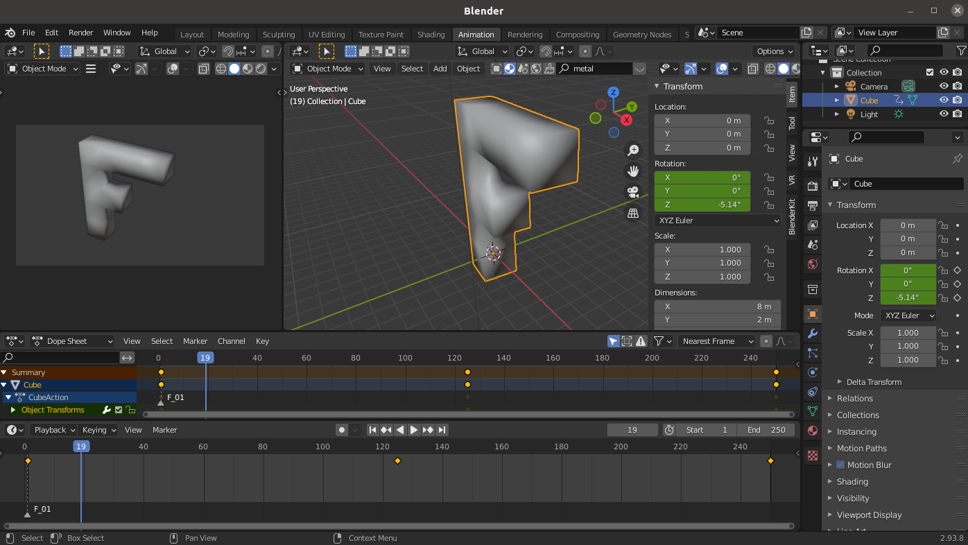
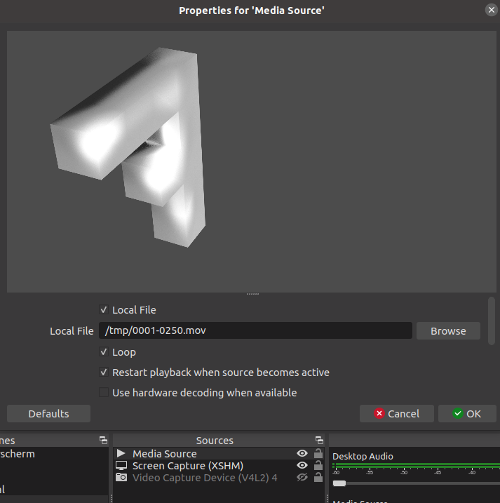
First test to make a personalised logo for myself to use embedded on movies or in OBS streams.
Created a simple animation in Blender.
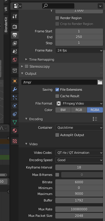
We need to export in RGBA (A for aplha), One of the supported video codex you can use is : Quicktime – QT rle. Select this one, and make sure it’s RGBA and not RGB
Now i can use the exported video file in OBS for streaming. I made the animation i a way that it can be looped. (Don’t forget to set this option in OBS.)
Also useable in Kdenlive editor as watermark.
"If something is worth doing, it's worth overdoing."