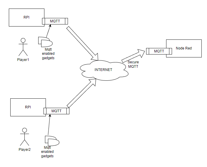
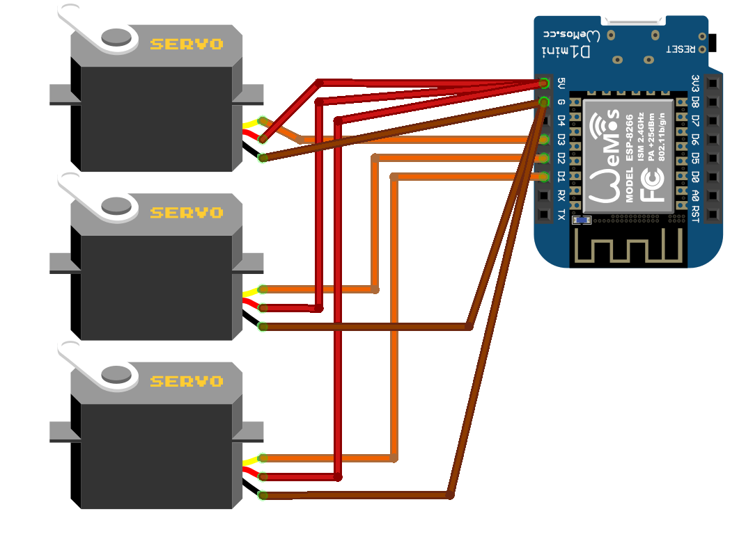
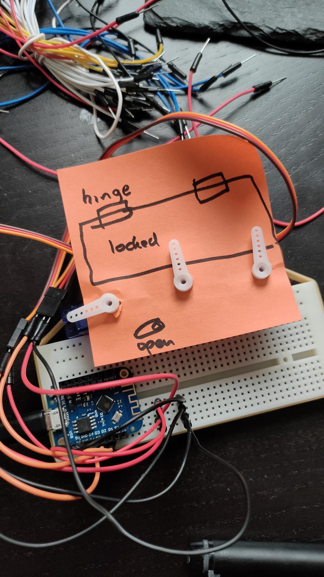
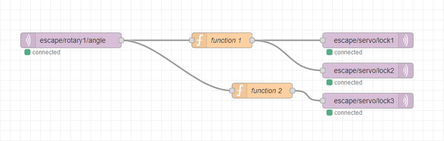
Multiple rotary encoders are controlling a servo based lock. 3 players have to work together to open the lock.
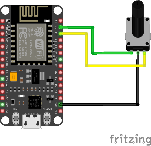
Arduino Rotary button (mqtt)
#include <ESP8266WiFi.h>
#include <WiFiClientSecure.h>
#include <time.h>
#include <PubSubClient.h>

#define encoderCLK 5   //D1
#define encoderDT 4    //D2
int servoAngle = 0;
int crntCLK;
int prvsCLK;
String myString;
char ang[50];

#ifndef SECRET
const char ssid[] = "MYSSID";
const char pass[] = "MSSIDPASS";

#define HOSTNAME "rotary1"

const char MQTT_HOST[] = "securemqttserver";
const int MQTT_PORT = 8883;
const char MQTT_USER[] = "user"; // leave blank if no credentials used
const char MQTT_PASS[] = "pass"; // leave blank if no credentials used

const char MQTT_SUB_TOPIC[] = "escape/" HOSTNAME "/in";
const char MQTT_PUB_TOPIC[] = "escape/" HOSTNAME "/out";
const char MQTT_PUB_TOPIC_angle[] = "escape/" HOSTNAME "/angle";

#ifdef CHECK_CA_ROOT
static const char digicert[] PROGMEM = R"EOF(
-----BEGIN CERTIFICATE-----
MIIFtTCCA52gAwIBAgIUXEEQRLHhYox8a95YiAYX/wQ/XeMwDQYJKoZIhvcNAQEN
----8< snip snap
CyLjTT2rtllw==
-----END CERTIFICATE-----
)EOF";
    #endif

    #ifdef CHECK_PUB_KEY
    // Extracted by: openssl x509 -pubkey -noout -in ca.crt
    static const char pubkey[] PROGMEM = R"KEY(
    -----BEGIN PUBLIC KEY-----
    xxxxxxxxxxxxxxxxxxxxxxxxxxxxxxxxxxxxxxxxxxxxxxxxxxxxxxxxxxxxxxxx
    xxxxxxxxxxxxxxxxxxxxxxxxxxxxxxxxxxxxxxxxxxxxxxxxxxxxxxxxxxxxxxxx
    xxxxxxxxxxxxxxxxxxxxxxxxxxxxxxxxxxxxxxxxxxxxxxxxxxxxxxxxxxxxxxxx
    xxxxxxxxxxxxxxxxxxxxxxxxxxxxxxxxxxxxxxxxxxxxxxxxxxxxxxxxxxxxxxxx
    xxxxxxxxxxxxxxxxxxxxxxxxxxxxxxxxxxxxxxxxxxxxxxxxxxxxxxxxxxxxxxxx
    xxxxxxxxxxxxxxxxxxxxxxxxxxxxxxxxxxxxxxxxxxxxxxxxxxxxxxxxxxxxxxxx
    xxxxxxxxxxxxxxxxxxxxxxxxxxxxxxxxxxxxxxxxxxxxxxxxxxxxxxxxxxxxxxxx
    xxxxxxxxxxxxxxxxxxxxxxxxxxxxxxxxxxxxxxxxxxxxxxxxxxxxxxxxxxxxxxxx
    xxxxxxxx
    -----END PUBLIC KEY-----
    )KEY";
    #endif

    #ifdef CHECK_FINGERPRINT
	// Extracted by: openssl x509 -fingerprint -in ca.crt
    static const char fp[] PROGMEM = "AA:BB:CC:DD:EE:FF:00:11:22:33:44:55:66:77:88:99:AA:BB:CC:DD";
    #endif
#endif

//////////////////////////////////////////////////////

#if (defined(CHECK_PUB_KEY) and defined(CHECK_CA_ROOT)) or (defined(CHECK_PUB_KEY) and defined(CHECK_FINGERPRINT)) or (defined(CHECK_FINGERPRINT) and defined(CHECK_CA_ROOT)) or (defined(CHECK_PUB_KEY) and defined(CHECK_CA_ROOT) and defined(CHECK_FINGERPRINT))
  #error "cant have both CHECK_CA_ROOT and CHECK_PUB_KEY enabled"
#endif

BearSSL::WiFiClientSecure net;
PubSubClient client(net);

time_t now;
unsigned long lastMillis = 0;

void mqtt_connect()
{
  while (!client.connected()) {
    Serial.print("Time: ");
    Serial.print(ctime(&now));
    Serial.print("MQTT connecting ... ");
    if (client.connect(HOSTNAME, MQTT_USER, MQTT_PASS)) {
      Serial.println("connected.");
      client.subscribe(MQTT_SUB_TOPIC);
    } else {
      Serial.print("failed, status code =");
      Serial.print(client.state());
      Serial.println(". Try again in 5 seconds.");
      /* Wait 5 seconds before retrying */
      delay(5000);
    }
  }
}

void receivedCallback(char* topic, byte* payload, unsigned int length) {
  Serial.print("Received [");
  Serial.print(topic);
  Serial.print("]: ");
  for (int i = 0; i < length; i++) {
    Serial.print((char)payload[i]);
  }
}

void setup()
{
  pinMode (encoderCLK,INPUT_PULLUP);
  pinMode (encoderDT,INPUT_PULLUP);
  prvsCLK = digitalRead(encoderCLK);
  Serial.begin(115200);
  Serial.println();
  Serial.println();
  Serial.print("Attempting to connect to SSID: ");
  Serial.print(ssid);
  WiFi.hostname(HOSTNAME);
  WiFi.mode(WIFI_STA);
  WiFi.begin(ssid, pass);
  while (WiFi.status() != WL_CONNECTED)
  {
    Serial.print(".");
    delay(1000);
  }
  Serial.println("connected!");

  Serial.print("Setting time using SNTP");
  configTime(1 * 3600, 0, "pool.ntp.org", "time.nist.gov");
  now = time(nullptr);
  while (now < 1510592825) {
    delay(500);
    Serial.print(".");
    now = time(nullptr);
  }
  Serial.println("done!");
  struct tm timeinfo;
  gmtime_r(&now, &timeinfo);
  Serial.print("Current time: ");
  Serial.print(asctime(&timeinfo));

  #ifdef CHECK_CA_ROOT
    BearSSL::X509List cert(digicert);
    net.setTrustAnchors(&cert);
  #endif
  #ifdef CHECK_PUB_KEY
    BearSSL::PublicKey key(pubkey);
    net.setKnownKey(&key);
  #endif
  #ifdef CHECK_FINGERPRINT
    net.setFingerprint(fp);
  #endif
  #if (!defined(CHECK_PUB_KEY) and !defined(CHECK_CA_ROOT) and !defined(CHECK_FINGERPRINT))
    net.setInsecure();
  #endif

  client.setServer(MQTT_HOST, MQTT_PORT);
  client.setCallback(receivedCallback);
  mqtt_connect();
}

void loop()
{
   crntCLK = digitalRead(encoderCLK);

 if (crntCLK != prvsCLK){
      // If the encoderDT state is different than the encoderCLK state then the rotary encoder is rotating counterclockwise
        if (digitalRead(encoderDT) != crntCLK) {
          servoAngle ++;

        }
        else {
          servoAngle --;
         }
         Serial.println(servoAngle);
          String myString = String(servoAngle);
          myString.toCharArray(ang, myString.length() + 1);
          client.publish(MQTT_PUB_TOPIC_angle, ang, false);
 }
  prvsCLK = crntCLK;

  now = time(nullptr);
  if (WiFi.status() != WL_CONNECTED)
  {
    Serial.print("Checking wifi");
    while (WiFi.waitForConnectResult() != WL_CONNECTED)
    {
      WiFi.begin(ssid, pass);
      Serial.print(".");
      delay(10);
    }
    Serial.println("connected");
  }
  else
  {
    if (!client.connected())
    {
      mqtt_connect();
    }
    else
    {
      client.loop();
    }
  }

  if (millis() - lastMillis > 5000) {
    lastMillis = millis();
    client.publish(MQTT_PUB_TOPIC, ctime(&now), false);
  }
}
Arduino 3 servos using mqtt
#include <ESP8266WiFi.h>
#include <PubSubClient.h>
#include <Servo.h>
Servo lock1;
Servo lock2;
Servo lock3;

const char* ssid = "MYSSID";                // WiFi SSID
const char* password = "MYSSIDPASS";        // WiFi Password
const char* mqtt_server = "MQTTSERVER";  // IP Broker MQTT
const char* topic_lock1 = "escape/servo/lock1";
const char* topic_lock2 = "escape/servo/lock2";
const char* topic_lock3 = "escape/servo/lock3";

WiFiClient espClient;
PubSubClient client(espClient);
long lastMsg = 0;
char msg[50];
int value = 0;

void setup() {

  Serial.begin(115200);
  lock1.attach(D1);
  lock2.attach(D2);
  lock3.attach(D3);
  setup_wifi();
  client.setServer(mqtt_server, 1883);
  client.setCallback(callback);
}

void setup_wifi() {
  delay(10);
  // We start by connecting to a WiFi network
  Serial.println();
  Serial.print("Connecting to ");
  Serial.println(ssid);

  WiFi.begin(ssid, password);

  while (WiFi.status() != WL_CONNECTED) {
    delay(500);
    Serial.print(".");
  }

  Serial.println("");
  Serial.println("WiFi connected");
  Serial.println("IP address: ");
  Serial.println(WiFi.localIP());
}

void callback(char* topic, byte* payload, unsigned int length) {
 String string;
 Serial.print("Message arrived [");
 Serial.print(topic);
 Serial.print("] ");
 for (int i = 0; i < length; i++) {
 string+=((char)payload[i]);
 }
 Serial.print(string);
 Serial.print(" toInt ");
 int pos = string.toInt();
 Serial.println(pos);


 if ( strcmp(topic, topic_lock1) == 0 ) {
 Serial.print("lock1 ");
 Serial.println(pos);
 lock1.write(pos);
 }
 if ( strcmp(topic, topic_lock2) == 0 ) {
 Serial.print("lock2 ");
 Serial.println(pos);
 lock2.write(pos);
 }
 if ( strcmp(topic, topic_lock3) == 0 ) {
 Serial.print("lock3 ");
 Serial.println(pos);
 lock3.write(pos);
 }

 delay(15);
}

void reconnect() {
  // Loop until we're reconnected
  while (!client.connected()) {
    Serial.print("Attempting MQTT connection...");
    // Attempt to connect
    if (client.connect("ESP8266servolocks")) {
      Serial.println("connected");
      client.subscribe(topic_lock1);
      client.subscribe(topic_lock2);
      client.subscribe(topic_lock3);
    } else {
      Serial.print("failed, rc=");
      Serial.print(client.state());
      Serial.println(" try again in 5 seconds");
      // Wait 5 seconds before retrying
      delay(5000);
    }
  }
}
void loop() {
  if (!client.connected()) {
    reconnect();
  }
  client.loop();
  delay(100);
}