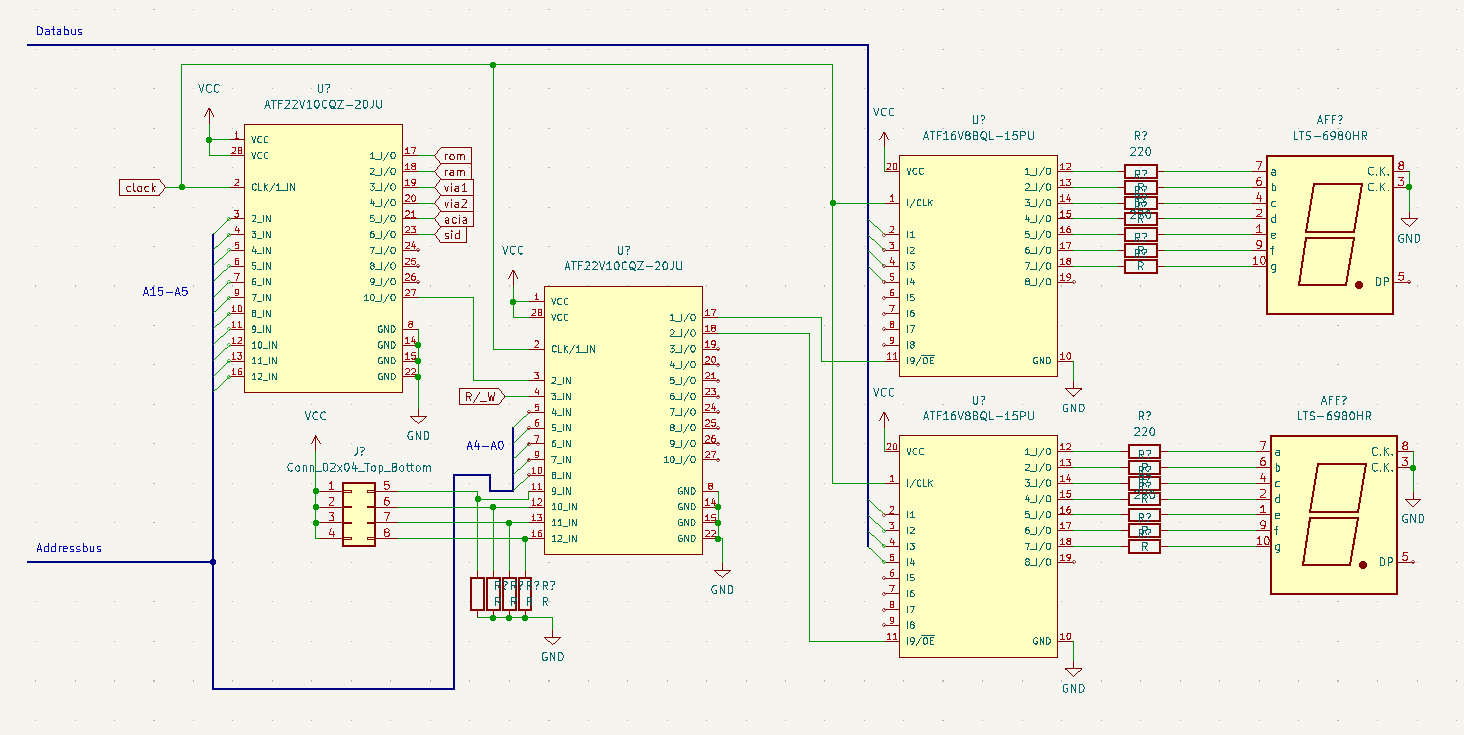
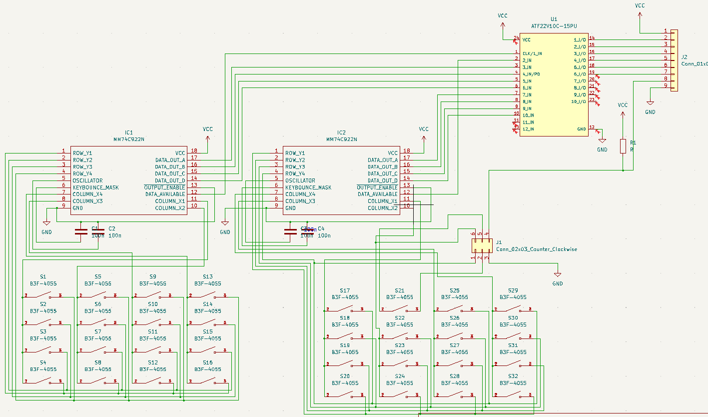
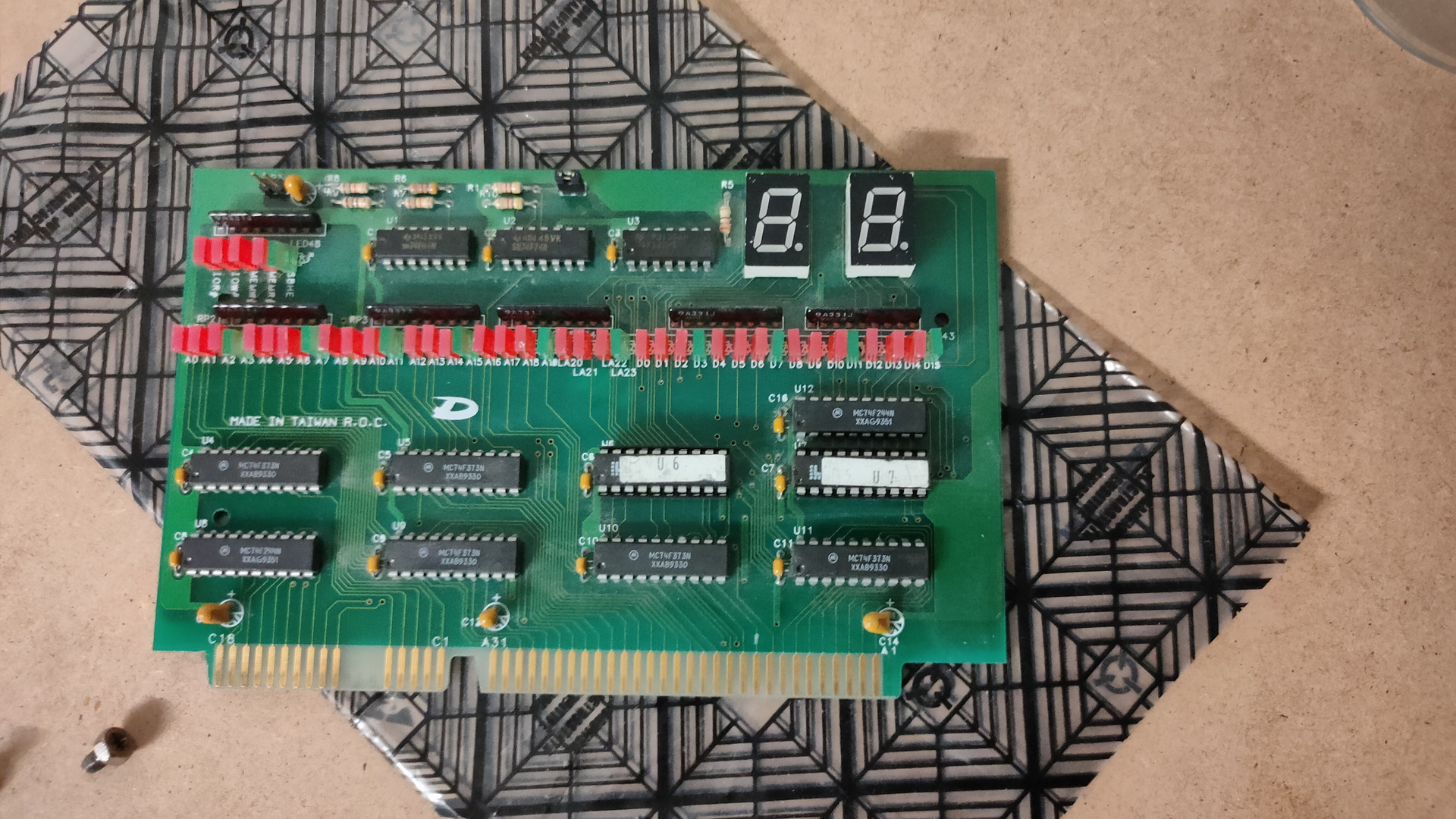
Sometimes when i’m writing code i want to know what’s happening. For example when i’m working on the display, there is maybe no output. With the above example i can write to address $01F0 (example address), and it will display on the 7 Segment displays.
Upperleft PLD is my address decoder, which has been running for a while now.
Secondary PLD adds the rest of the Addressbus lines, and gives me the opportunity to select in a range of 16 addresses, using jumpers/
The two smaller PLD’s latch the databus data when addressed. AND decodes a nibble to 7-Segment output for 0-9A-F. (There are apparently no chips available which do A-F)
I’m going to add the PLD code when everything works. Let me know if you like the idea.
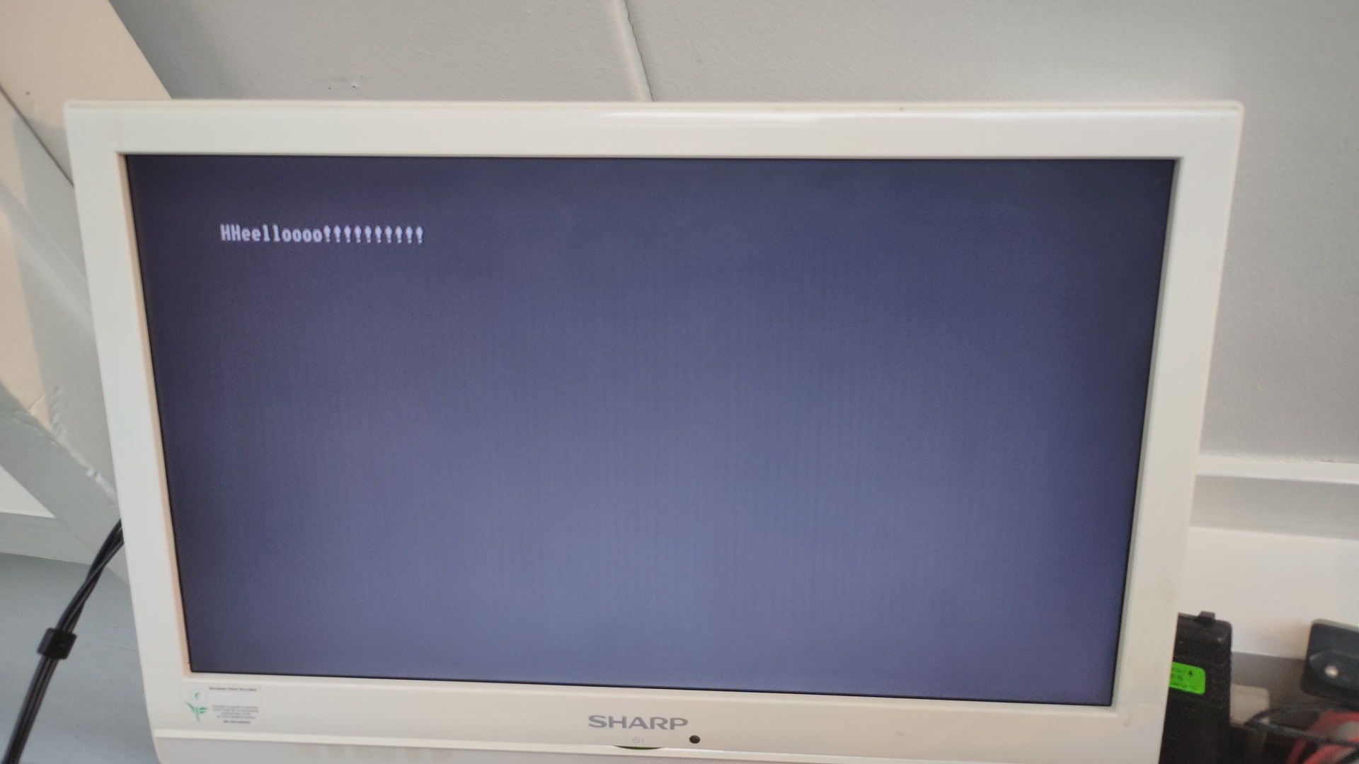
No more sync issues! (see post https://www.henriaanstoot.nl/2022/10/19/composite-video-with-atmega328p/ )
There are some duplicate characters, the input device below does not have a proper debounce method.
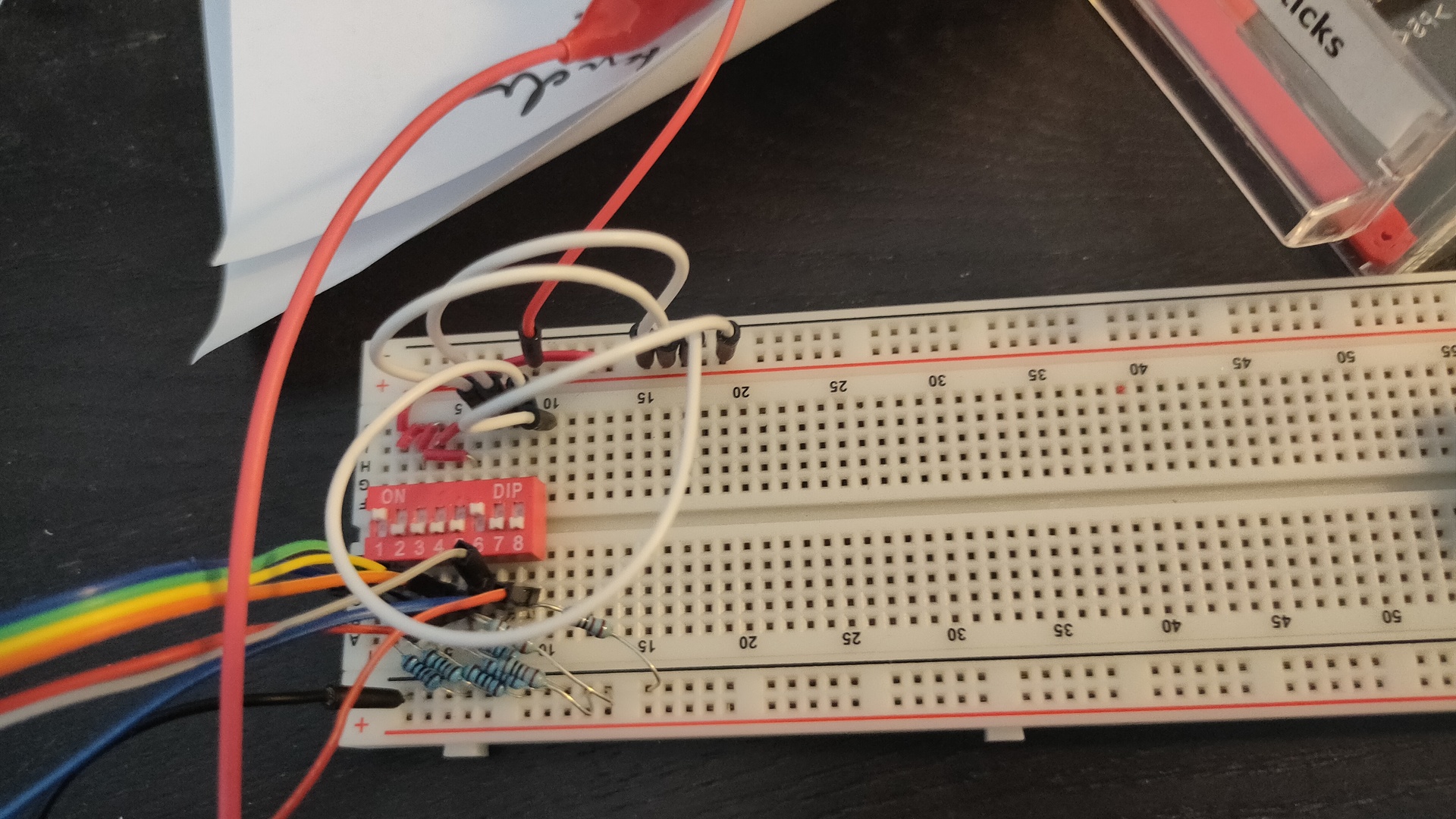
My temporary input device (note hex 21 is a “!” character)
No need to fix the debounce, the dipswitches are temporary. This will be controlled by the VIA 6522 chip.
UPDATE 20221108 (Connected to second VIA)
PORTB = $5000
PORTA = $5001
DDRB = $5002
DDRA = $5003
clock = $e0
E = %10000000
RW = %01000000
RS = %00000000
.org $0200
reset:
ldx #$ff
txs
lda #%11111111 ; Set all pins on port B to output
sta DDRB
lda #%10000000 ; Set top pin on port A to output
sta DDRA
lda #$00 ; reset bit
sta PORTA
sta clock
ldx #0
print:
lda message,x
beq printborder
jsr print_char
inx
jmp print
loop:
jmp loop
message:
.db 0x01,0x04,0x0C,0x0E,0x10,0x0F,0x08
.db 0x05,0x0a,0x0a
.db 0x05,0x0b,0x0b
.asc "Composite Video 6502 - 20221108"
.db 0x0E,0x11,0x0F,0x0C
.asciiz " With 2 pixels "
waitloop:
pha
tya
pha
ldy #$ff
back:
dey
bne back
pla
tay
pla
rts
print_char:
sta PORTB
jsr waitloop
jsr waitloop
lda clock
eor #%10000000
sta clock
sta PORTA
jsr waitloop
lda clock
eor #%10000000
sta PORTA
jsr waitloop
rts
Control codes as from : http://searle.x10host.com/MonitorKeyboard/index.html
Video display control codes:
Hex (Decimal) and meaning
01 (01) - Cursor home (Standard ASCII)
02 (02) - Define cursor character (2nd byte is the curs character, or 00 to turn off) <--New for 3.0
03 (03) - Cursor blinking
04 (04) - Cursor solid
05 (05) - Set graphics pixel (next two bytes = x,y) <--New for 3.0
06 (06) - Reset graphics pixel (next two bytes = x,y) <--New for 3.0
08 (08) - Backspace (Standard ASCII)
09 (09) - Tab (Standard ASCII)
0A (11) - Linefeed (Standard ASCII)
0C (12) - Clear screen (Standard ASCII)
0D (13) - Carriage return (Standard ASCII)
0E (14) - Set column 0 to 79 (2nd byte is the column number) or 0 to 39 for a 40 char line
0F (16) - Set row 0 to 24 (2nd byte is the row number)
10 (16) - Delete start of line
11 (17) - Delete to end of line
12 (18) - Delete to start of screen
13 (19) - Delete to end of screen
14 (20) - Scroll up
15 (21) - Scroll down
16 (22) - Scroll left
17 (23) - Scroll right
18 (24) - Set font attribute for the current line (see elsewhere on this page for details) <--New for 3.0
1A (26) - Treat next byte as a character (to allow PC DOS char codes 1 to 31 to be displayed on screen)
1B (27) - ESC - reserved for ANSI sequences
1C (28) - Cursor right
1D (29) - Cursor Left
1E (30) - Cursor up
1F (31) - Cursor down
20 (32) to 7E (126) - Standard ASCII codes
7F (127) - Delete
80 (128) to FF (255) - PC (DOS) extended characters
There are a lot of old develop boards for all kinds for cpu’s.
These where build to learn machine code programming. Mostly made in the 80’s, and based on populair cpu’s at that time.
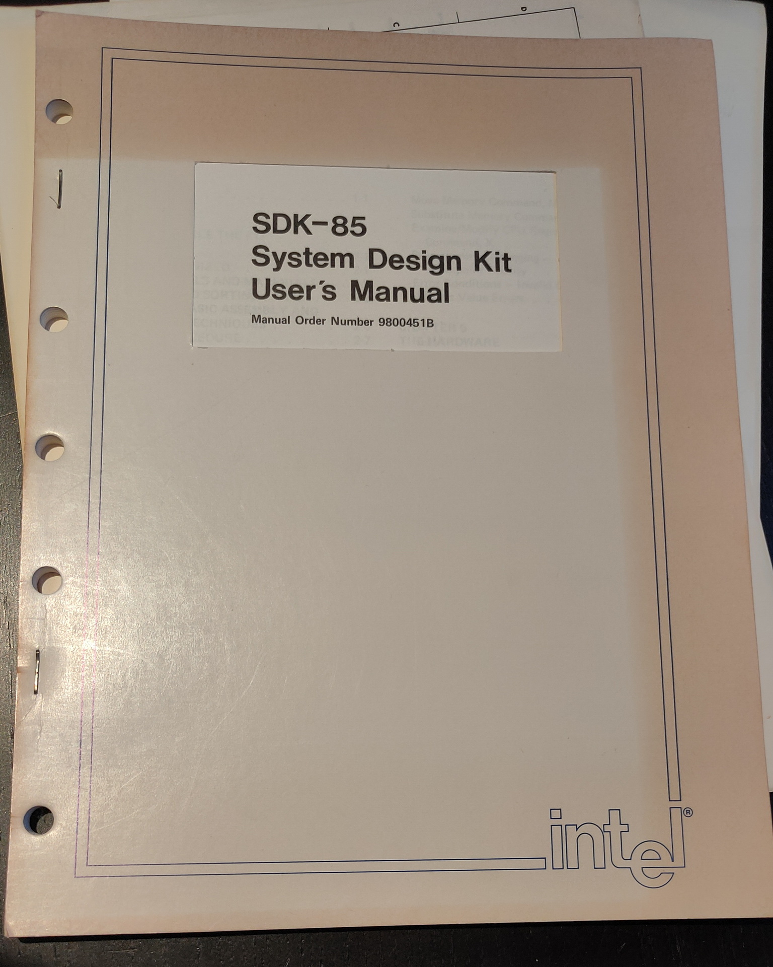
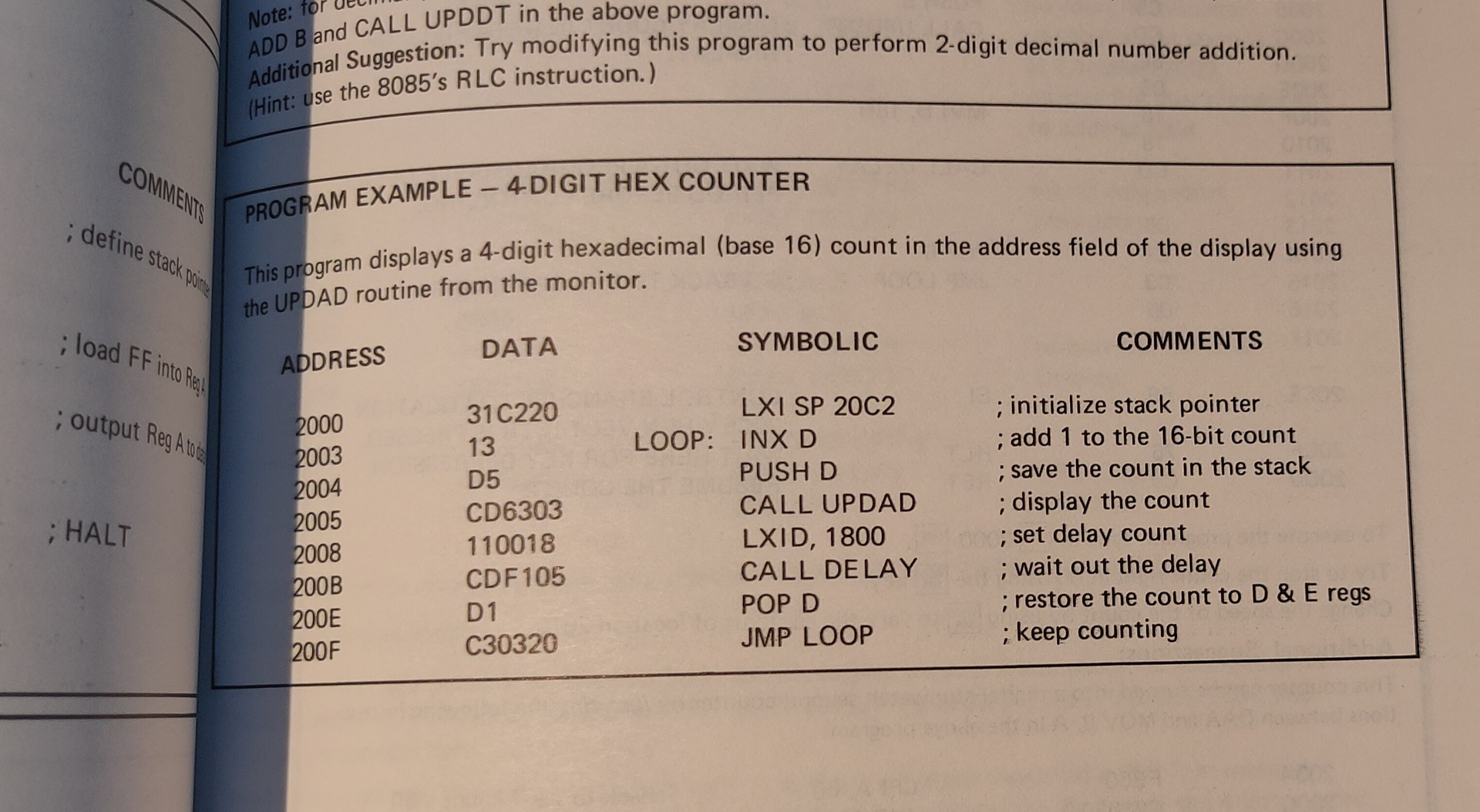
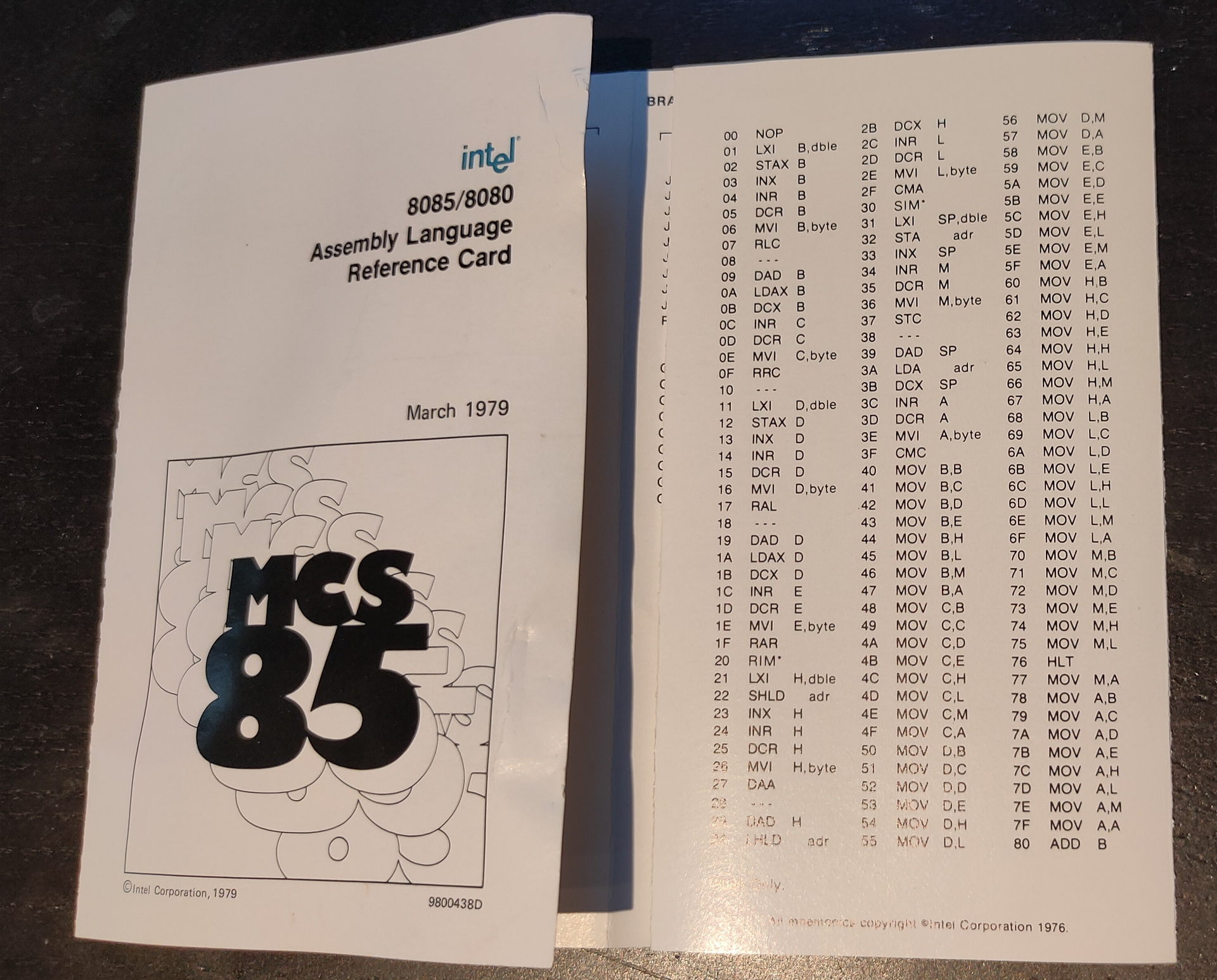
I own a some of these SDK’s (System Design Kits)
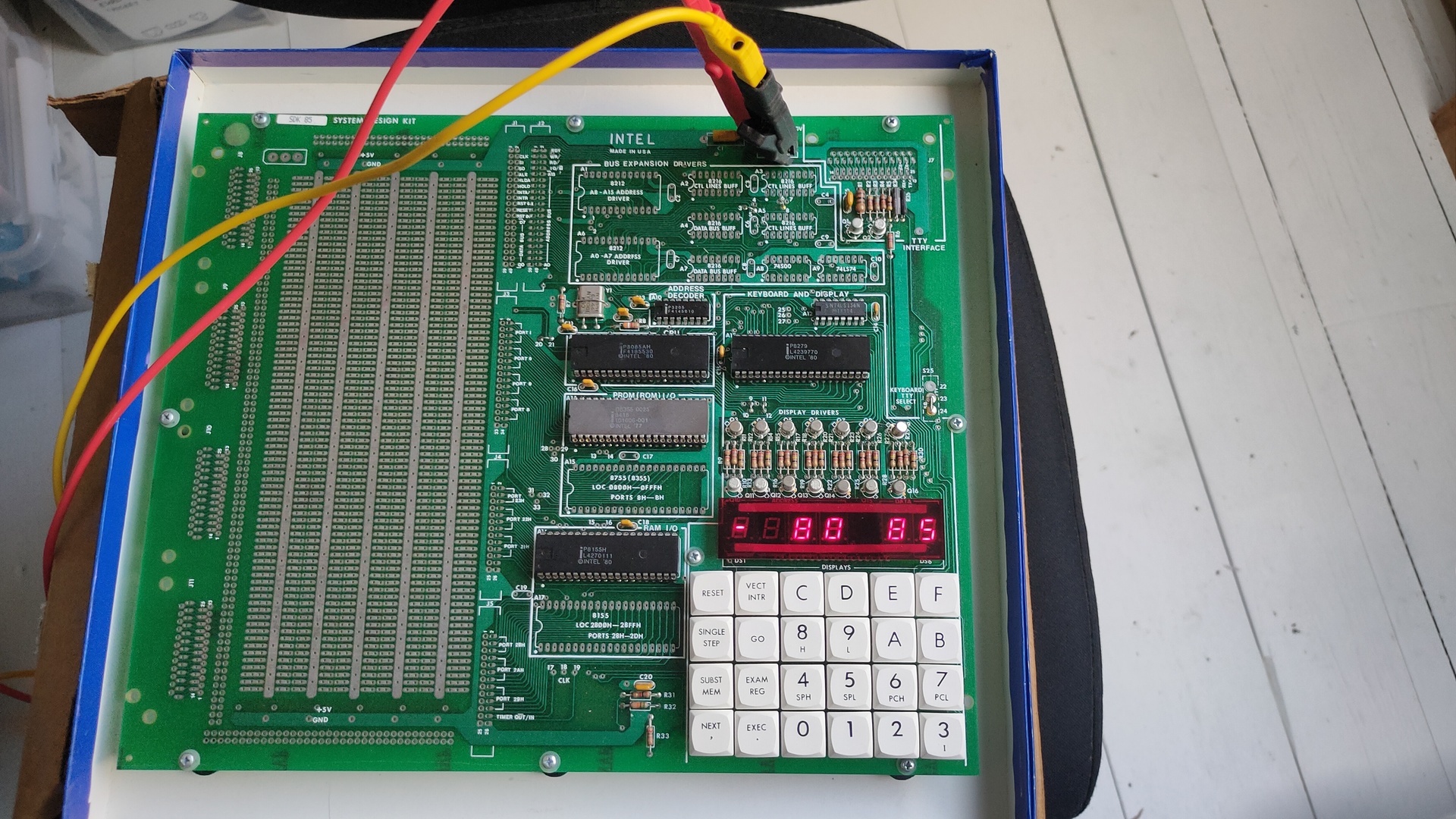
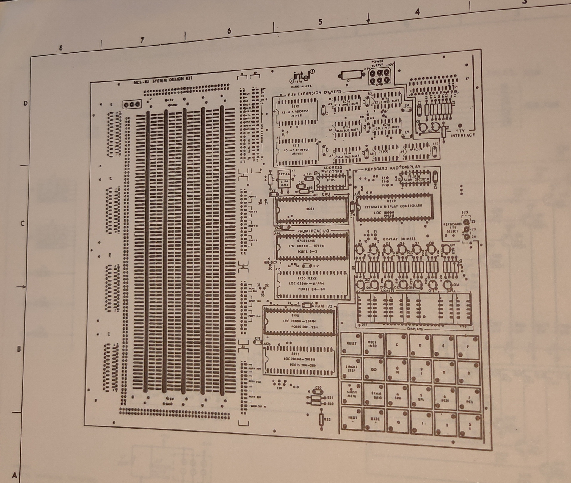
8085 – SDK85 i bought recently 8085 CPU
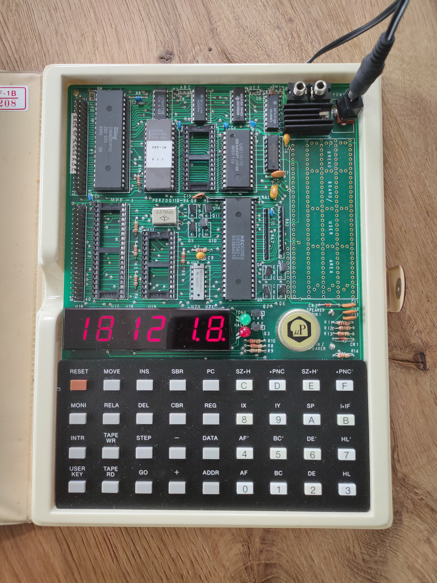
Microprofessor-1 (MPF-1) Z80 CPU
And my own 680x based computer
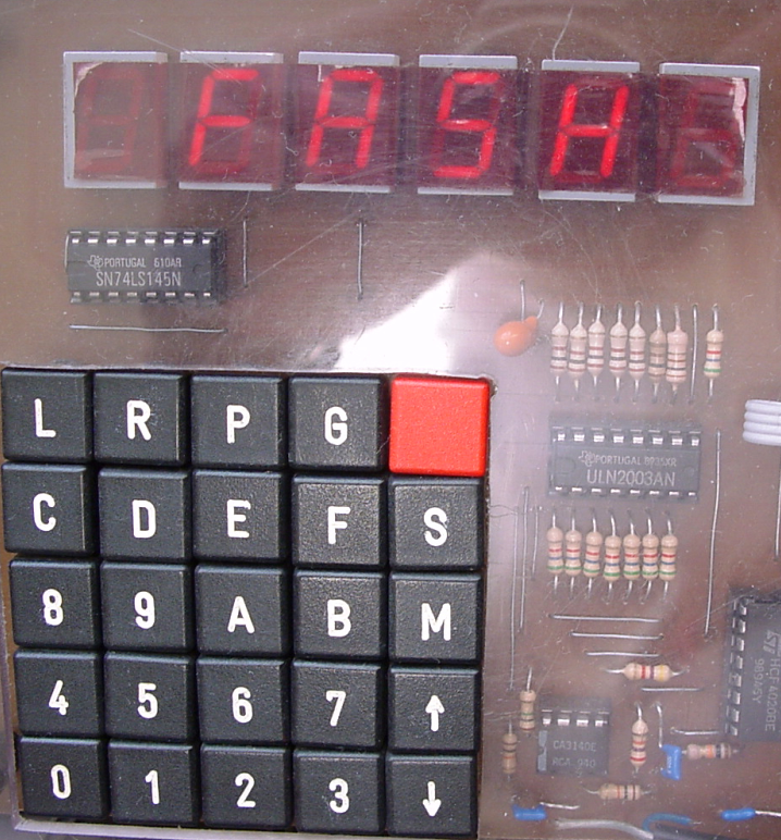
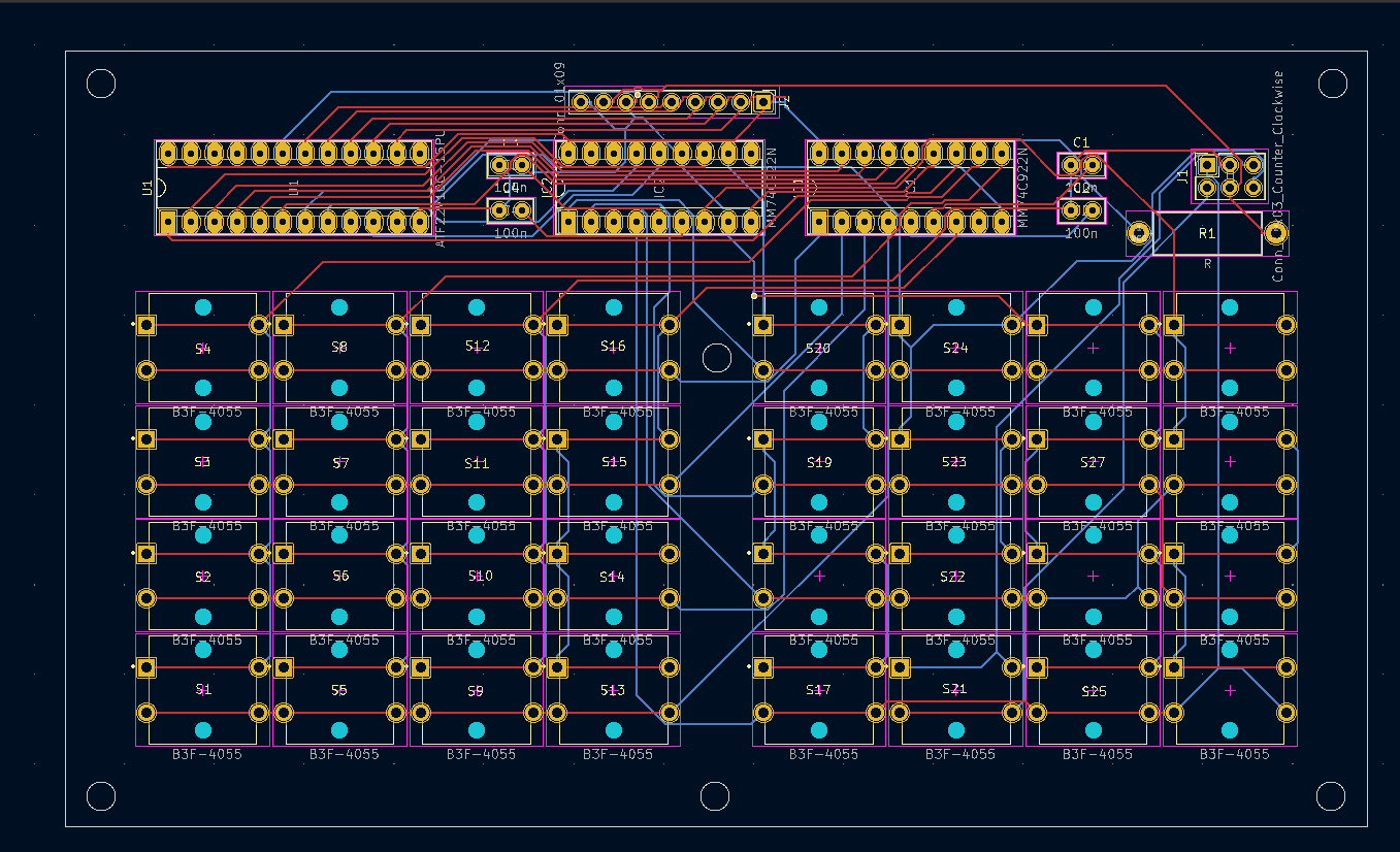
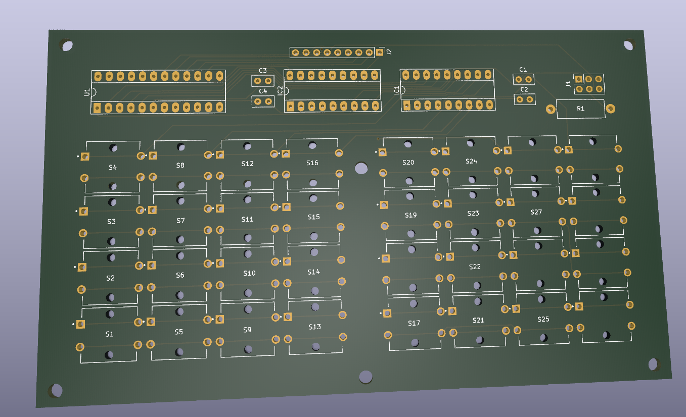
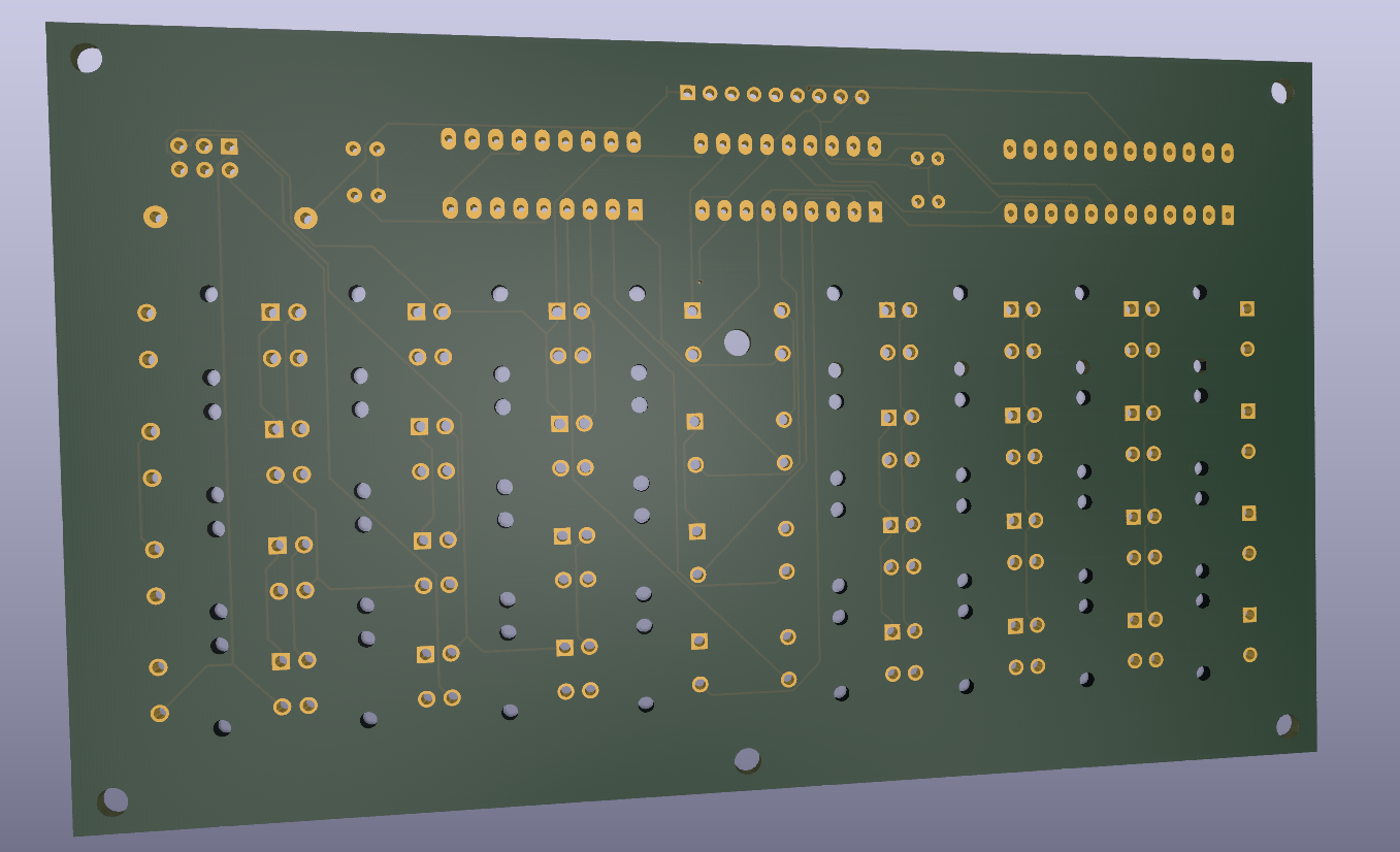
Most of these use a keyboard scanner which is also connected to 7 segment displays.
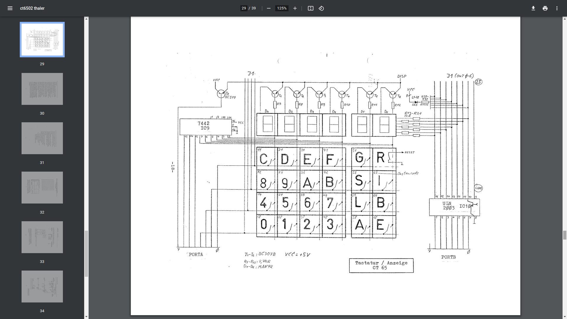
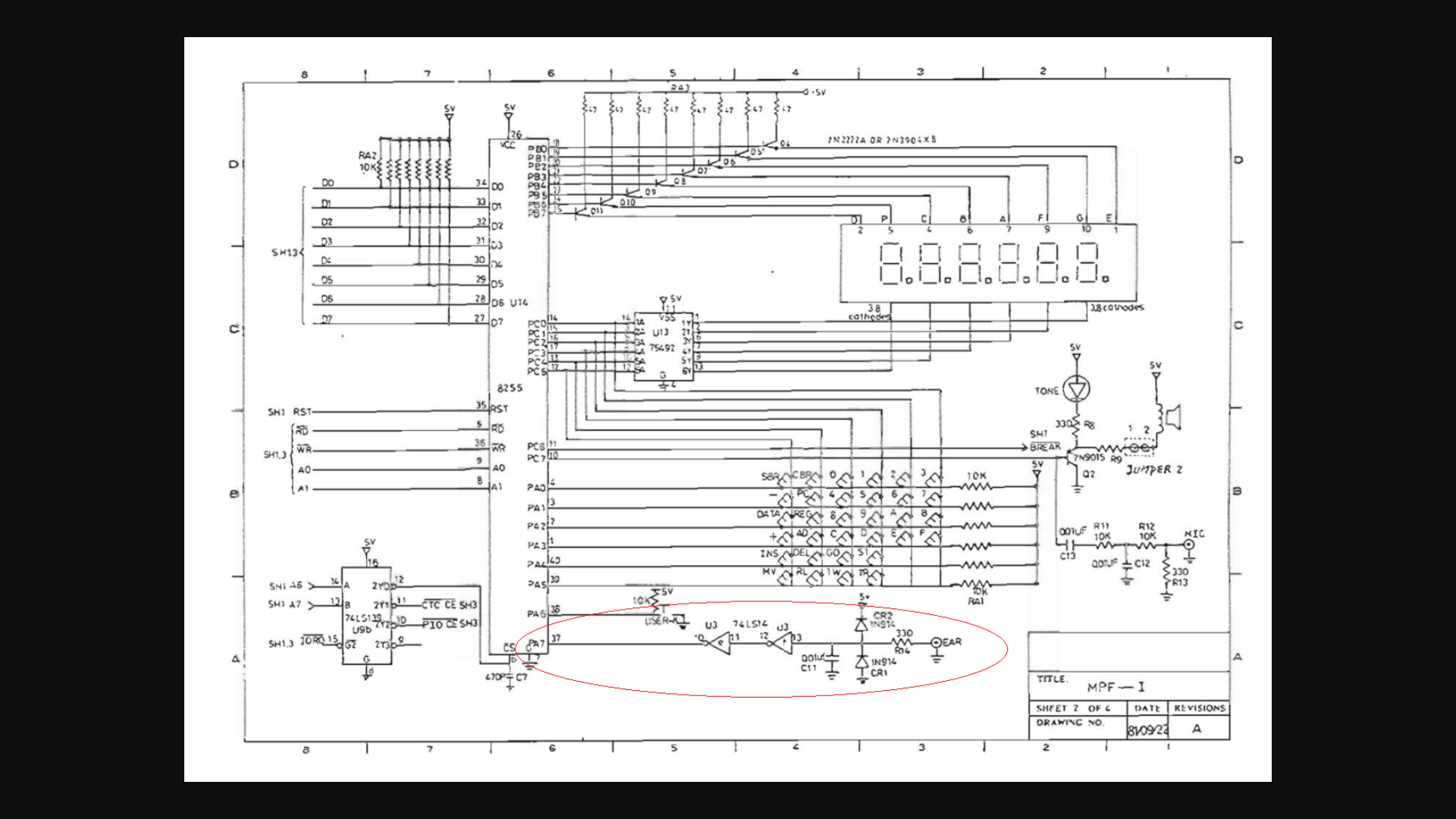
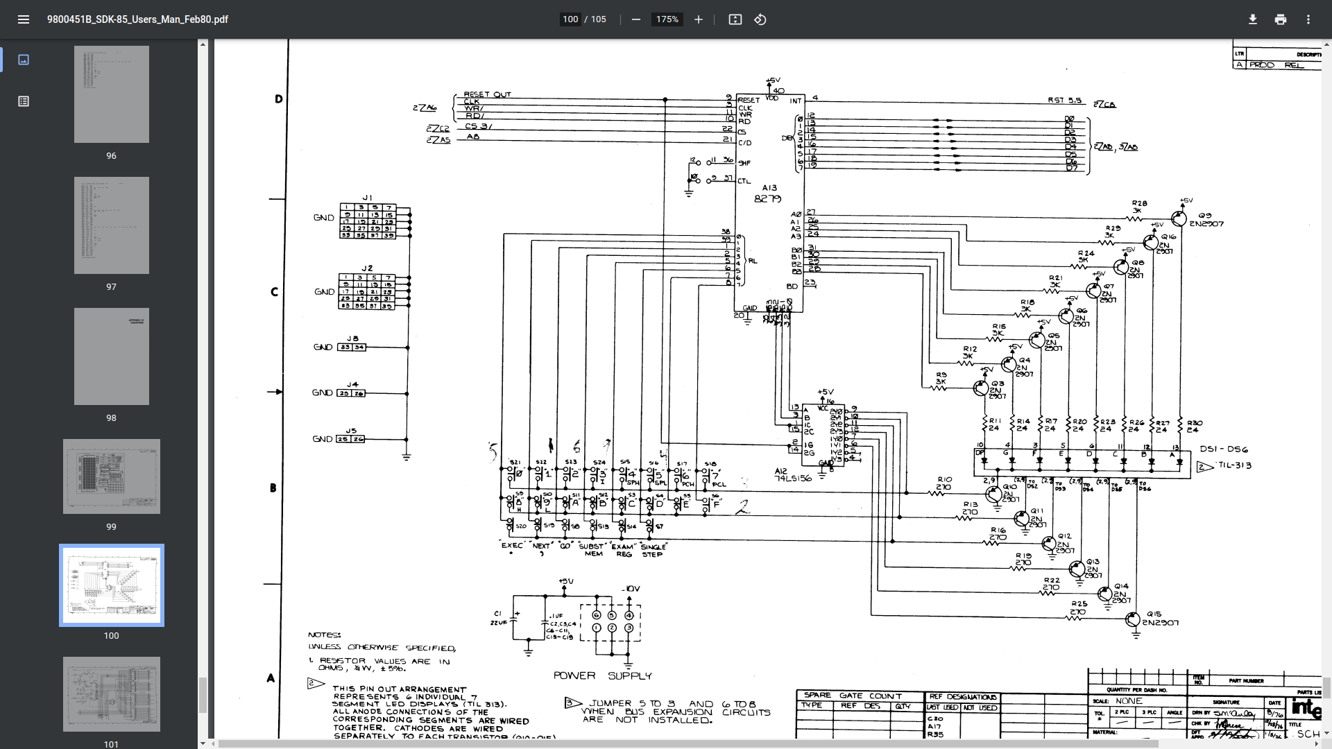
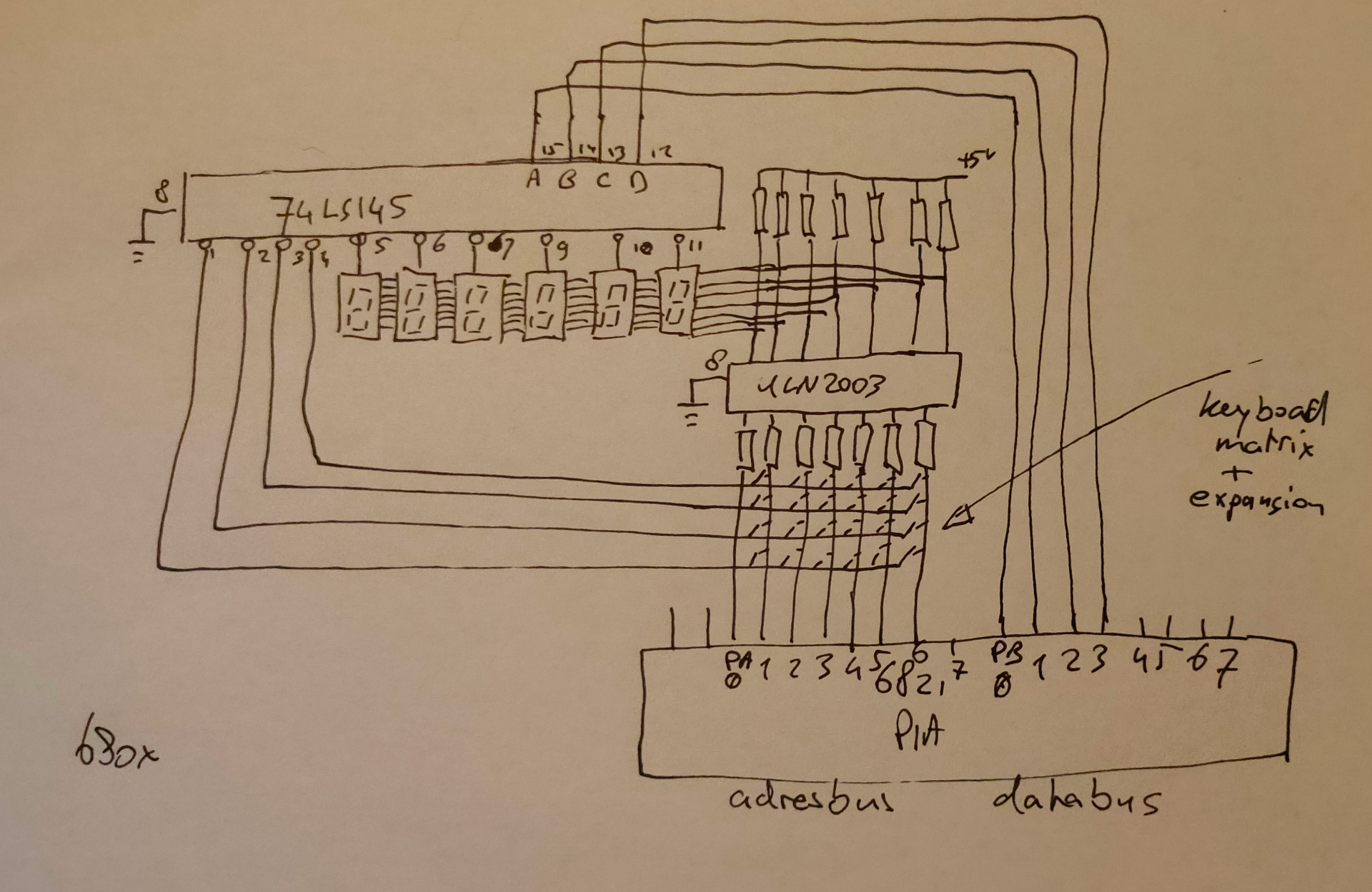
The way they work is practically the same. There is a VIA or PIA. Versitile interface adaptor, or Peripheral interface adaptor. These have two times 8 bits to control devices. When using 4 bits and convert these to 16 lines by using a 75ls145 for example. If you put a counter on those 4 bits, you sequently activate 1 of 16 lines. These lines you can use to scan a keyboard matrix OR display a character on a 7 segment display. These display’s won’t hold the data (and show the character) when not activated. The trick is to update de display fast enough so you don’t see the flickering on/off.
Activate a line and read a byte with the VIA = Reading keyboard row Activate a line and write a byte with the VIA = Display on a segment
These VIA/PIA’s where made with specific timings to match the CPU. 6522/6820/8255
Below you see some different implementations of these keyboard/display combo’s
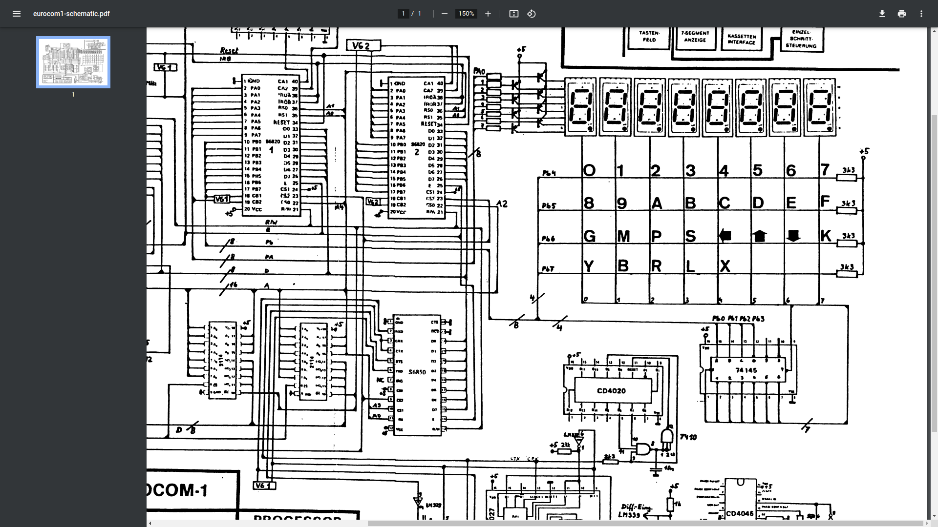
Thaler 6502 kit
Microprofessor MPF-1 kit (ignore red circle)
SDK85 kit
Eltec 6800
My version using darlington arrays (ULN2003)
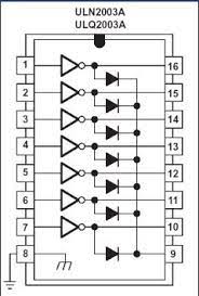
When looking at the 8085 version you see transistors being a ULN2003 is a chip with those transistors/amplification enclosed. It doesn´t draw much current from the bus, and diodes protect the way the current flows.
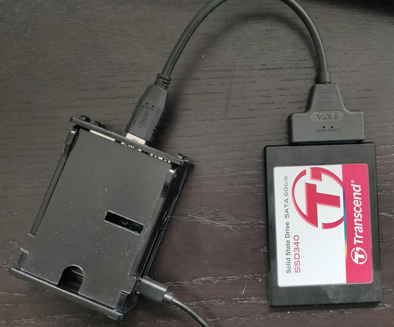
I had a crash recently on one of my raspberry-pi’s .. SDcard failure, they are not made for a lot of write actions. In the past i’ve changed some images to read only and with a r/w overlay. Also tmp filesystems in memory .. all not ideal.
So i’ve started to make every RPi ssd bootable.
I’ve got several ssd already from other projects. Sata to USB adaptors are cheap, only a few euro’s.
Steps to take:
Download Raspberry Pi Imager tool
Choose OS > Misc Utility Images > Bootloader > USB Boot
Select storage and write to a temporary sd-card (Not needed any more after flashing for normal operations)
Boot USB with this Micro-SDcard .. i didn’t have a screen connected .. So i just waited a few minutes
While i was waiting i wrote a OS image to the SSD using the same imager tool
Choose OS > select sata/ssd drive
Change options (cog), enable ssh, choose hostname and set password
Write to drive
Remove sdcard from RPi attach ssd/sata and boot
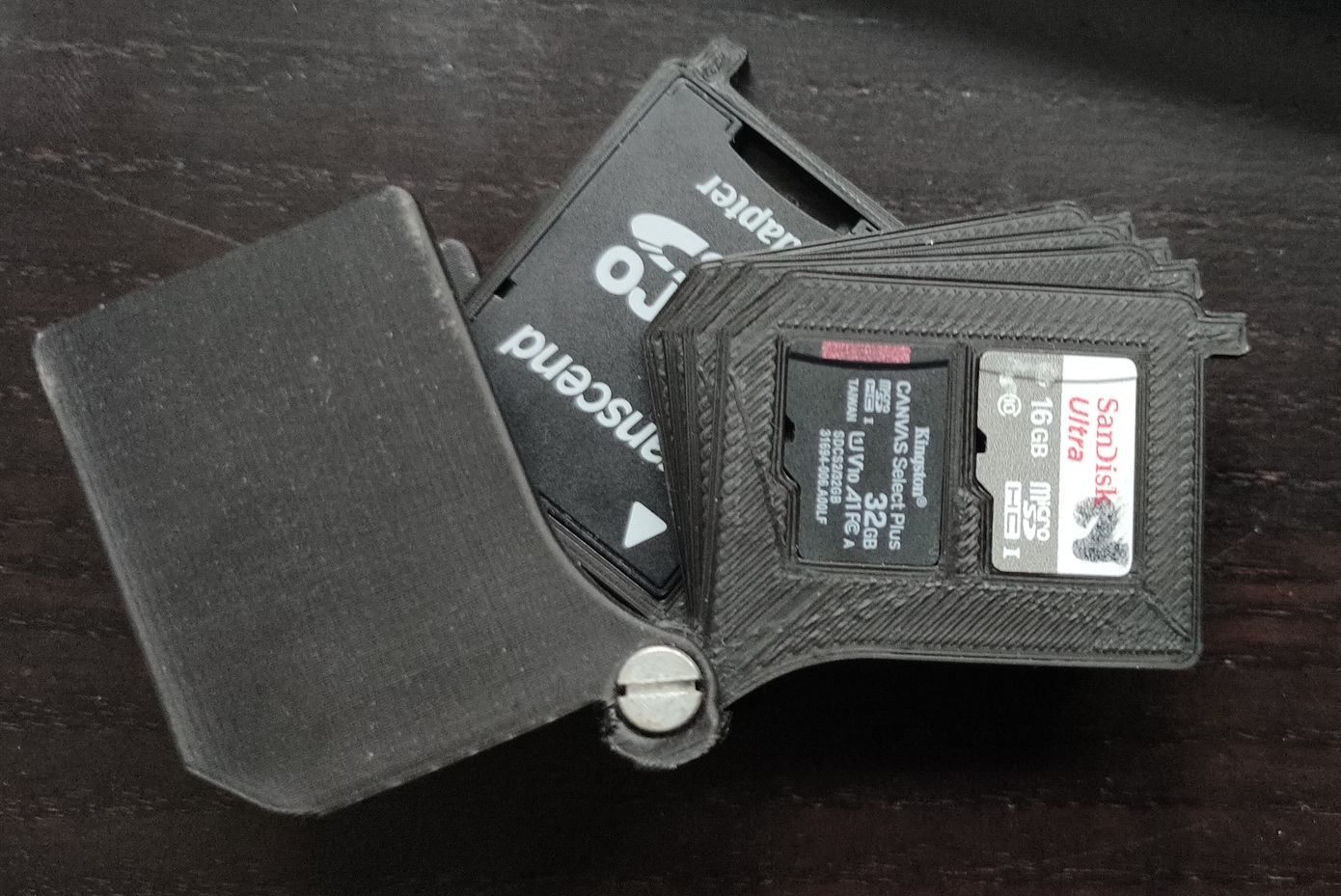
My 3D printed sdcard case, luckily there was still one in there (32GB kindda big, but it was only for temporary use .. 16GB was broken ..
So .. without attaching a screen or keyboard, just a network cable. I have a running OS on a RPi from SSD
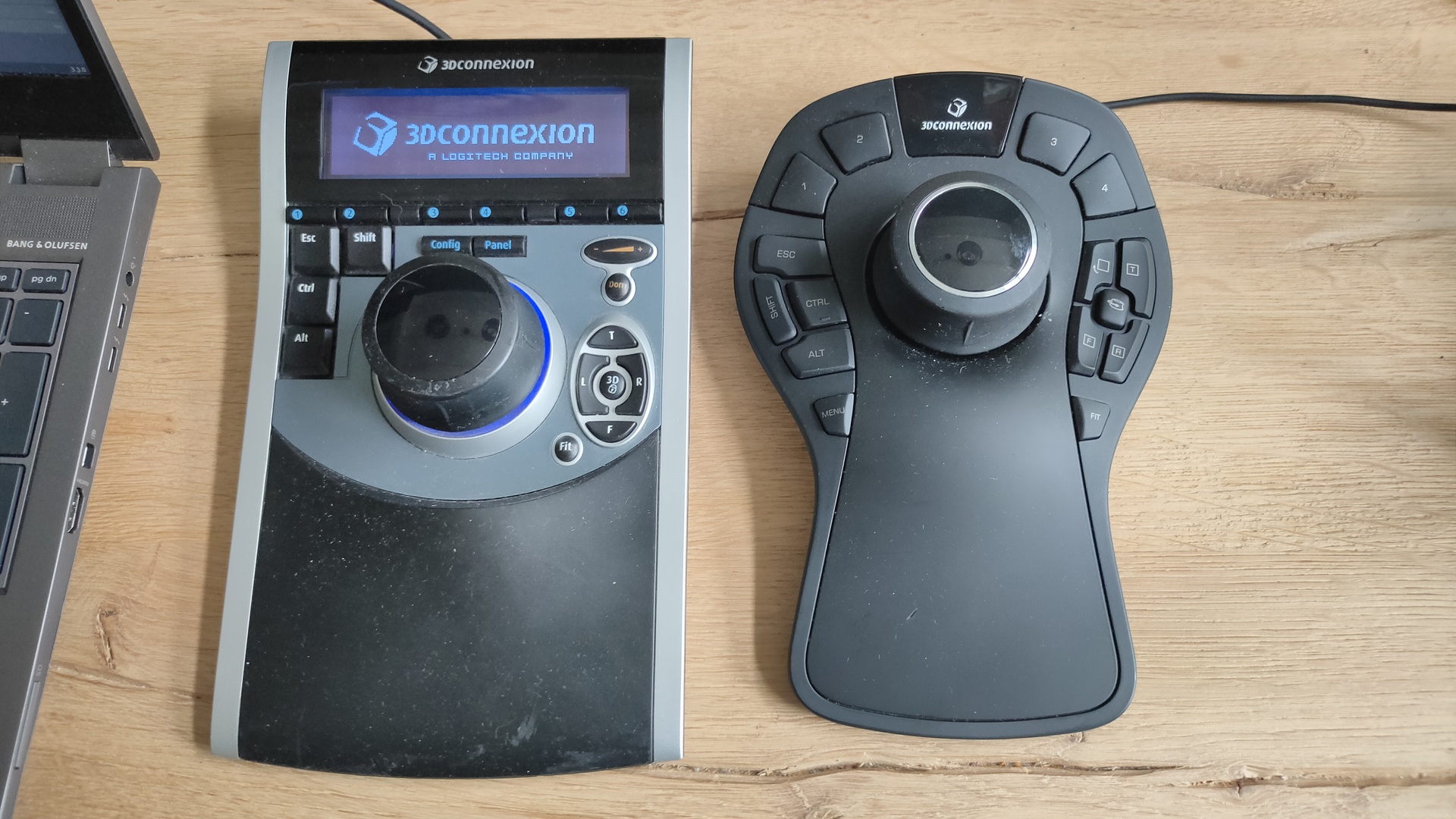
Yesterday i got two 3DConnexion 3D CAD mouses (mice) from my friend Vincent. While we where fixing his Mikrotik network i got to play with these cool devices.
I always wanted one of those, but they are quite expensive
First i tried to install the Software from 3DConnexion. It kindda worked but needed some workarounds and still wasn’t okay.
Downloaded 3dxware-linux-v1-8-0.x86_64.tar.gz (Maybe this version is TOO new, SpacePilot i a little ouder)
there is a install-3dxunix.sh, but it was made for Suse/Redhat
This program needed motif .. and a lot of libraries (libmotif/libxm)
After that some fonts xfonts-100dpi xfonts-75dpi
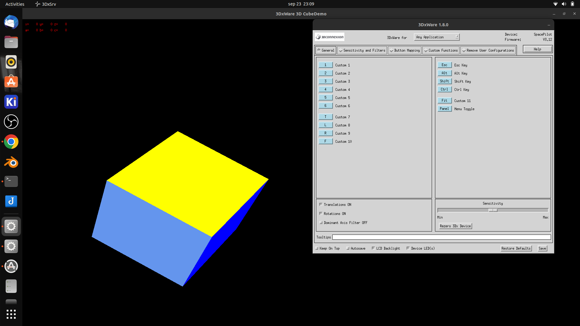
workaround was starting by
sudo /etc/3DxWare/daemon/3dxsvr -userName ${USER} -d usb
After that the demo program worked perfectly … but Blender didn’t After some tinkering it work a little, it was far to sensitive, and was all over the place.
Luckily i found a opensource replacement. https://spacenav.sourceforge.net/ git cloned the package, then i notished .. there is a precompiled version for ubuntu!
apt-get install spacenavd .. start the service .. and go!
i cloned the test demos (libspnav) and compiled those test programs.
apt-get install libglu1-mesa-dev
git clone https://github.com/FreeSpacenav/libspnav.git
cd libspnav
./configure
make
... fly is a nice little test program
So lets start blender
Pan tilt roll .. nice!
This wil speedup modeling, and for sure sculpting !
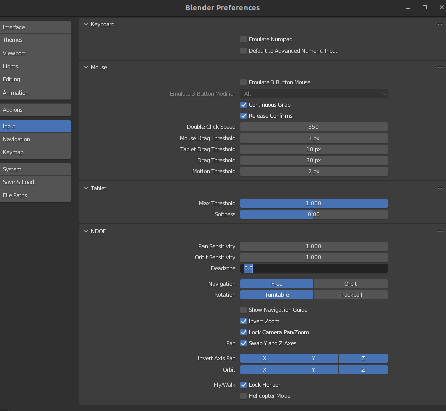
Some settings which worked for me .. let the tweaking begin!
UPDATE: 2022-09-29
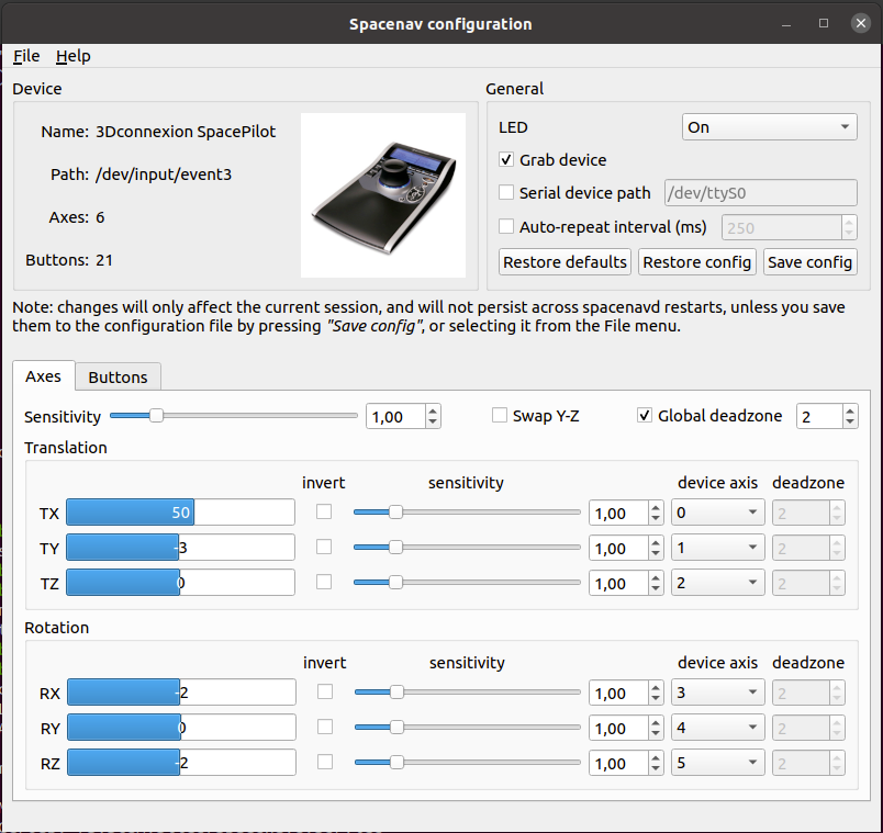
I removed the version in the apt repository, and installed everything from git. Now i have a cool configure tool
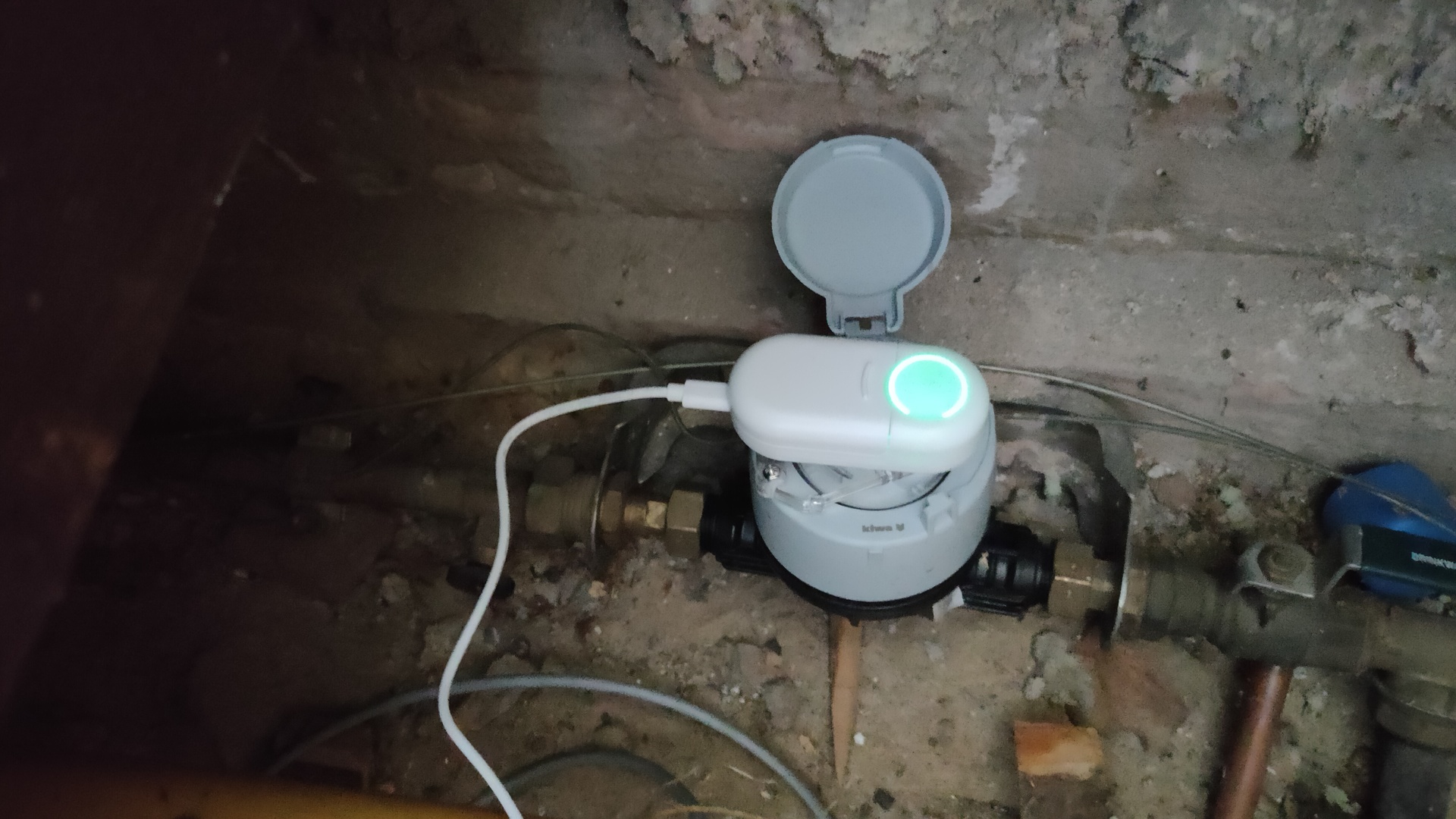
It’s a little device you can place on your watermeter.
You get a plastic clip/holder which you can use to place the device on your watermeter. You can easily remove the device to read the values.
The device measures the little round gauge, so it has no idea what the current values are. Add the current values of your meter to the output of the device.
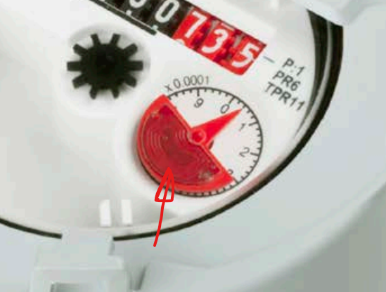
The device works by measuring the rotation of the red part.
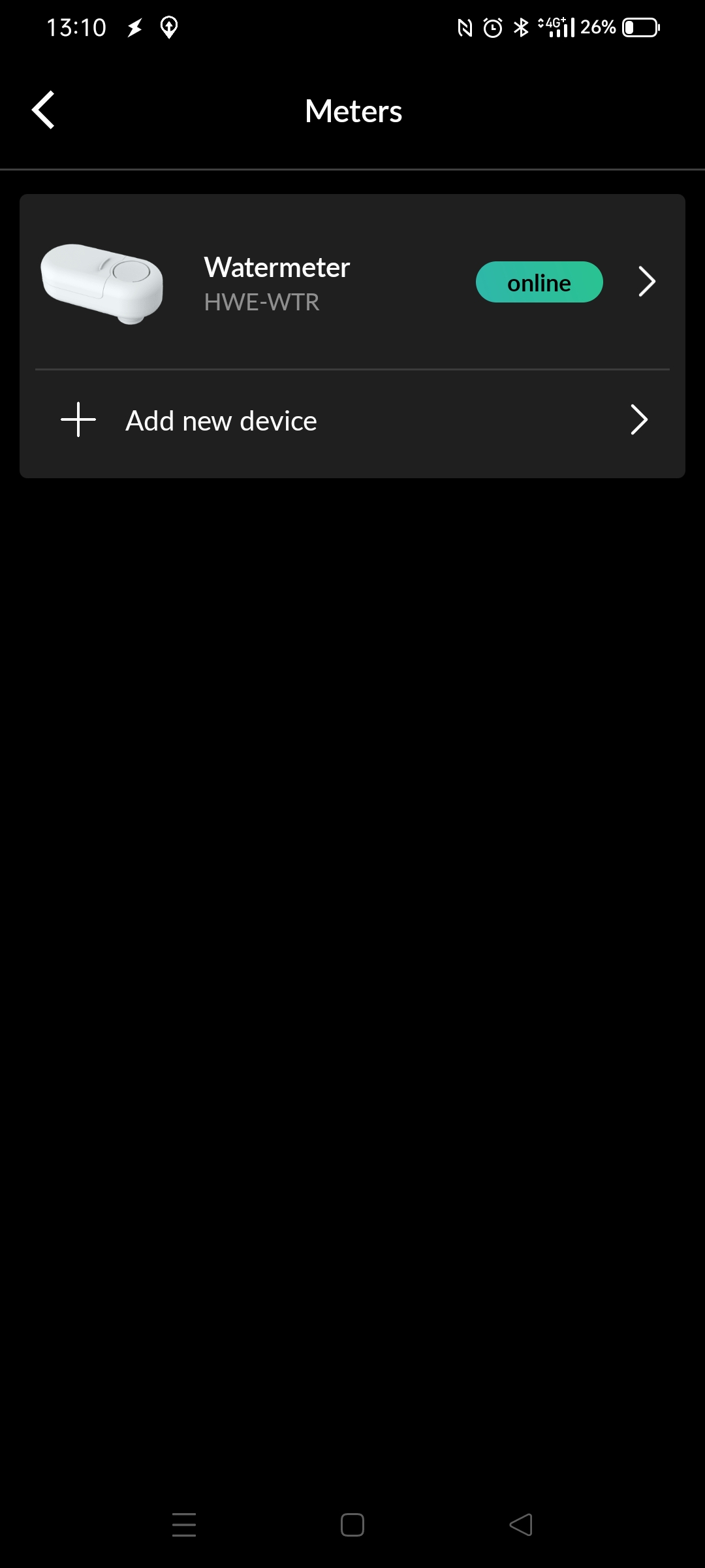
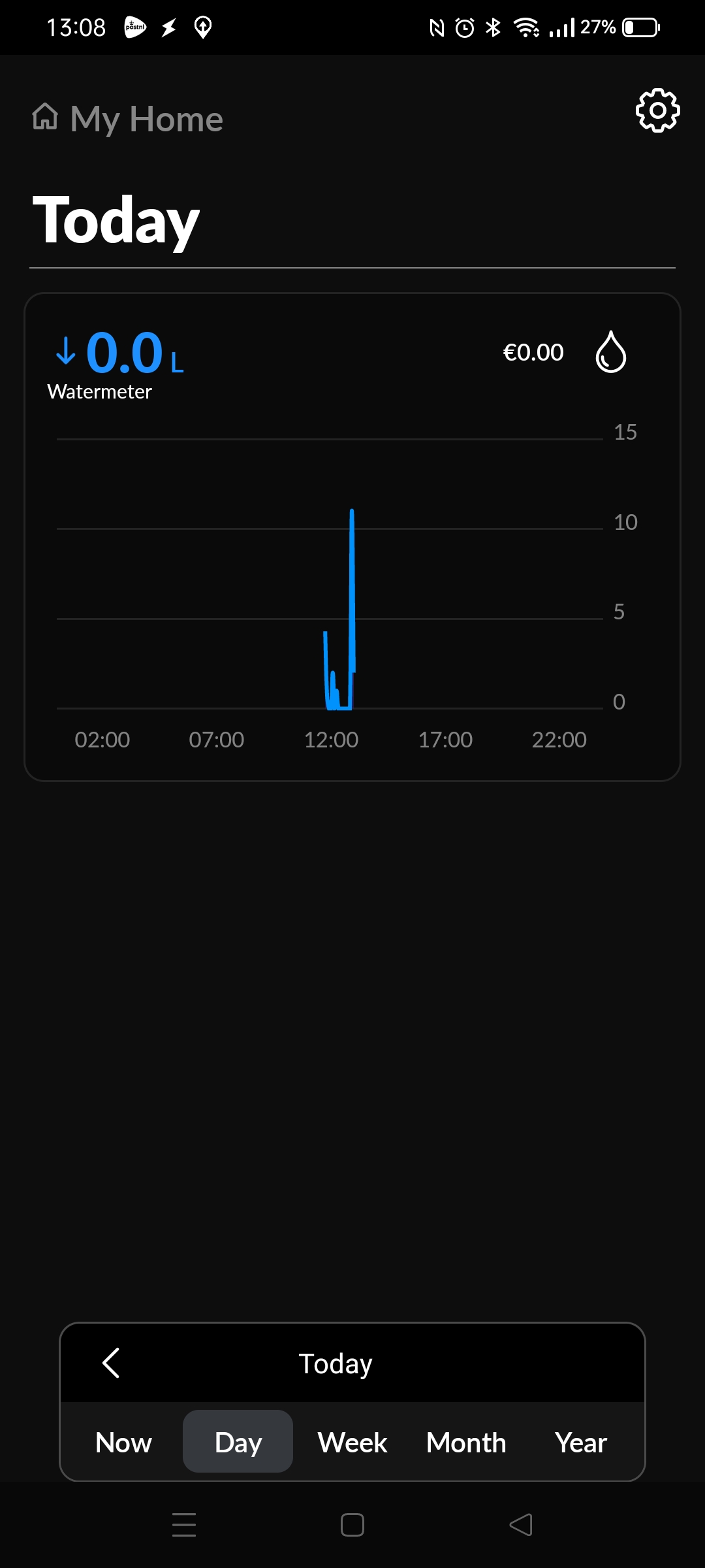
By default it sends the information over the internet to a server. Your phone connects to this server and the app wil give you the graphs.
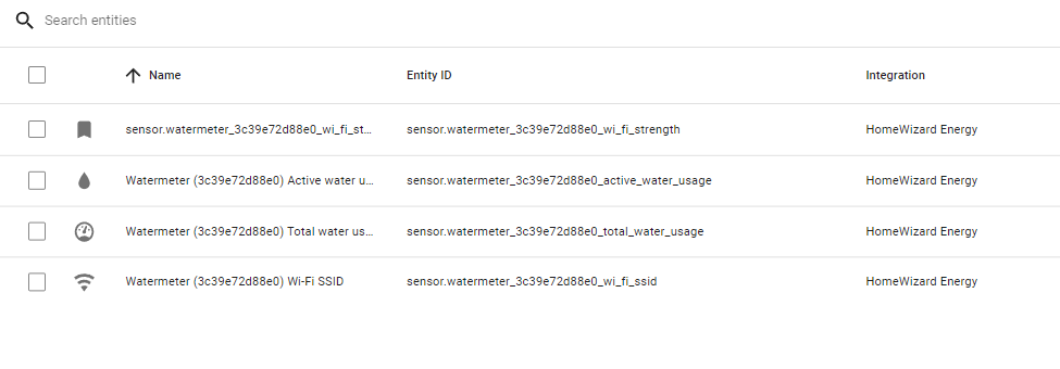
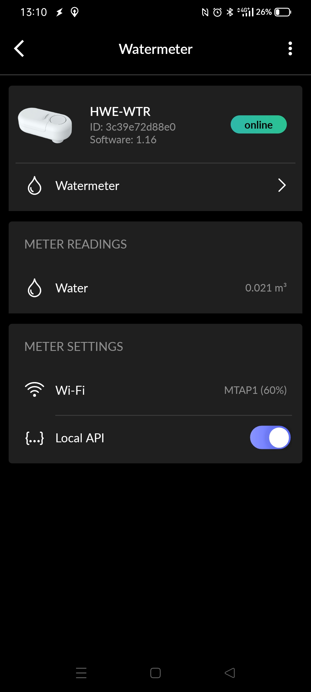
If you want your own intergration, you have to enable “local api” See image on the right. When you want realtime data, you have to connect a usb-c power supply. When using batteries, the device wil only connect to wifi once per 5 minutes, and you can’t use the API.
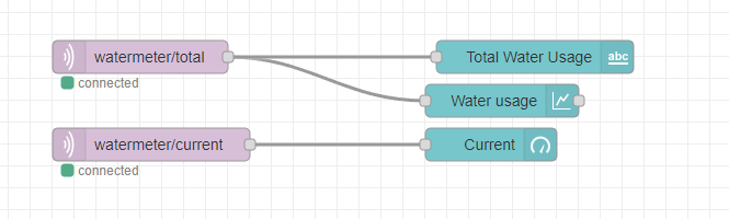
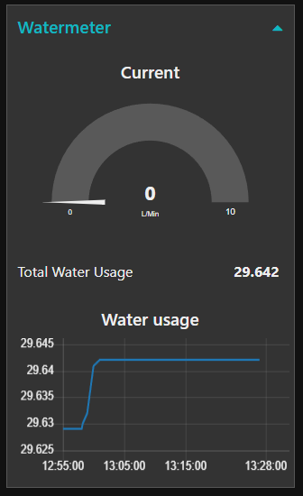
I wrote a little test script in bash to draw graphs using mqtt and Nodered.
Buzzer and led on VIA 2, blinky and sound timed by the internal timers of the 6522
ACIA testing still going on, writing software
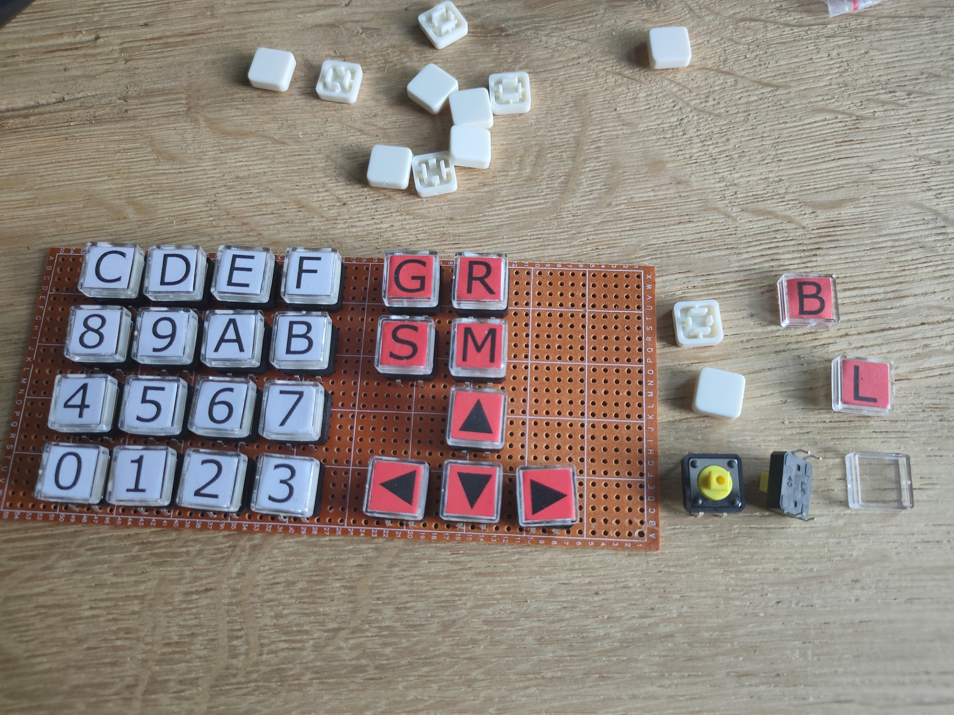
Mini matrix keyboard removed, and used the temporary cursor buttons for the test with a rom which allows for a 8bits upload method using a arduino and the 6522. (I’m working on the big keyboard)
Work in progress code
PORT2B = $5000 ; VIA PORTB
PORT2A = $5001 ; VIA PORTA
DDR2B = $5002 ; Data direction register
DDR2A = $5003 ; Data direction register
PORTB = $6000 ; display
PORTA = $6001 ; control display + matrix keyboard
DDRB = $6002 ; data direction register
DDRA = $6003 ; data direction register
SID = $7000 ; sid base address
E = %10000000 ; enable bit
RW = %01000000 ; RW bit
RS = %00100000 ; Register Select bit
HOME = %00000010 ; VIA PORTB HOME command
DADDR = %00010000 ; VIA DADDRESS
LINENO = $0200 ; temp address linenumber (move to other location)
NEXTLINE = 40 ; 2x16 Chars but internally 40
.org $8000
reset:
ldx #$ff
txs ; reset stack
; ###################################################
; # DISPLAY CONTROL #
; ###################################################
; VIA Setup
lda #%11111111 ; Set all pins on port B to output
sta DDRB
lda #%11100000 ; Set top 3 pins on port A to output
sta DDRA
; DISPLAY Setup
lda #%00111000 ; Set 8-bit mode; 2-line display; 5x8 font
jsr lcd_instruction
lda #%00001110 ; Display on; cursor on; blink off
jsr lcd_instruction
lda #%00000110 ; Increment and shift cursor; don't shift display
jsr lcd_instruction
lda #$00000001 ; Clear display
jsr lcd_instruction
; ###################################################
; # PRINT MESSAGE LINE NO 0 #
; ###################################################
lda #0 ; set line number
sta LINENO ; store for subroutine
jsr gotoline ; move cursor
ldx #0 ; message index pointer
print:
lda message0,x ; start of message
beq nextprint ; stop when null in message (asciiz <- Zero padded)
jsr print_char ; print char
inx ; incr index
jmp print ; resume print
; ###################################################
; # PRINT MESSAGE LINE NO 1 #
; ###################################################
nextprint:
lda #1 ; set line number
sta LINENO ; store
jsr gotoline
ldx #0 ; index pointer
print2:
lda message1,x ; absolute address message + x in A
beq sidsound ; if x is 0, end of message
jsr print_char ; jump subroutine
inx ; increment x
jmp print2 ; loop print2
; ###################################################
; # SID SOUND #
; ###################################################
sidsound:
lda #0
sta SID+$5 ; attack/decay duration
lda #250
sta SID+$6 ; sustain level/release duration
lda #$95 ; frequency voice 1 low byte
sta SID+$0
lda #$44 ; frequency voice 1 high byte
sta SID+$1
lda #%00100001 ; sawtooth + gate
sta SID+$4 ; control register voice 1
lda #$0f ; filter mode and volume (bits 3-0 main volume)
sta SID+$18 ; filter mode and volume
; ###################################################
; # 2ND VIA #
; ###################################################
lda #%11111111 ; set port A output
sta DDR2A
lda #%11111111 ; all ones!
sta PORT2A
; ###################################################
lda #%11111111 ; set port A output
sta DDR2A
lda #%11111111 ; all ones!
sta PORT2A
; ###################################################
; # MAIN PROGRAM LOOP #
; ###################################################
loop:
jmp loop
; 1234567812345678
message0: .asciiz "VIA 1,2 SID TEST"
message1: .asciiz " FASH 2022 "
; ###################################################
; # ONLY SUBROUTINES #
; ###################################################
; ###################################################
; # Subroutine gotoline #
; # Moves character placement position on display #
; # Needs : $LINENO ADDRESS #
; # Exit values : - #
; # Destroys registers: - #
; ###################################################
gotoline:
pha ; store a
txa
pha ; store x
ldx LINENO
lda #HOME ; cursor down
jsr lcd_instruction
lda #$80
nextline:
ldx LINENO
cpx #00
beq endnextlines
loopline:
adc #40
jsr lcd_instruction
dex
stx LINENO
jmp nextline
endnextlines:
pla ; pop a
tax ; a to x
pla ; pop a
rts
; ###################################################
; # LCD SUBROUTINES #
; ###################################################
lcd_wait:
pha
lda #%00000000 ; Port B is input
sta DDRB
lcdbusy:
lda #RW
sta PORTA
lda #(RW | E)
sta PORTA
lda PORTB
and #%10000000
bne lcdbusy
lda #RW
sta PORTA
lda #%11111111 ; Port B is output
sta DDRB
pla
rts
lcd_instruction:
jsr lcd_wait
sta PORTB
lda #0 ; Clear RS/RW/E bits
sta PORTA
lda #E ; Set E bit to send instruction
sta PORTA
lda #0 ; Clear RS/RW/E bits
sta PORTA
rts
print_char:
jsr lcd_wait
sta PORTB
lda #RS ; Set RS; Clear RW/E bits
sta PORTA
lda #(RS | E) ; Set E bit to send instruction
sta PORTA
lda #RS ; Clear E bits
sta PORTA
rts
nmi:
rti
irq:
rti
.org $fffa
.word nmi
.word reset
.word irq
; .word $0000
"If something is worth doing, it's worth overdoing."