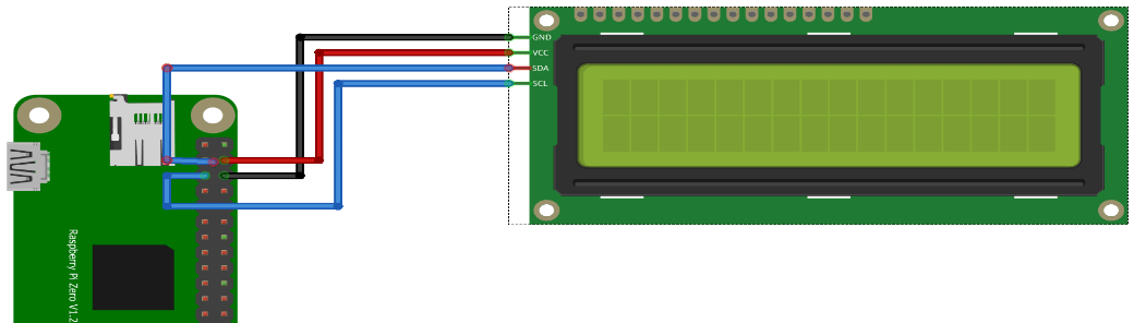
I’ve installed a headless Raspbian on a Pi Zero with a 2×16 Chars lcd display. As part of the Escape Room over the internet
Using the raspberry imager: I’ve set the username/password and ssh access in this tool. For wifi access i’ve placed below file on the SDcard in /boot (You can do this in the tool, but i want to make this dynamic when connected at a remote site.) file: wpa_supplicant.conf
sudo raspi-config
Interface options and enable I2C

sudo apt-get install python3-smbus

wget https://gist.githubusercontent.com/DenisFromHR/cc863375a6e19dce359d/raw/36b82e787450d127f5019a40e0a55b08bd43435a/RPi_I2C_driver.py
and
wget https://gist.githubusercontent.com/DenisFromHR/cc863375a6e19dce359d/raw/36b82e787450d127f5019a40e0a55b08bd43435a/examples.py

For python3 edit the example and put at the top

# requires RPi_I2C_driver.py
import RPi_I2C_driver
from time import *
unichr = chr

Run with
python3 examples.py
lcd display with i2c backpack
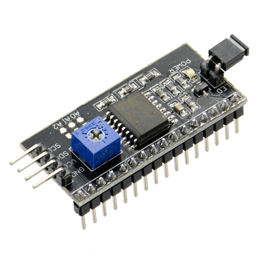
I2C backpack
Below is a mockup session.
Next todo:
Add more hardware (like buttons) to the RPI
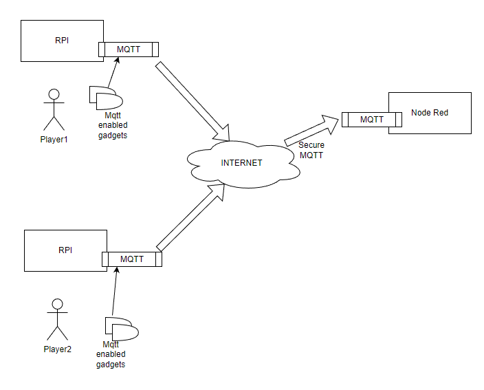
Configure an Accesspoint on this Rpi for other devices to connect to
Install a local Mqtt broker, which connects secure to my internet facing broker
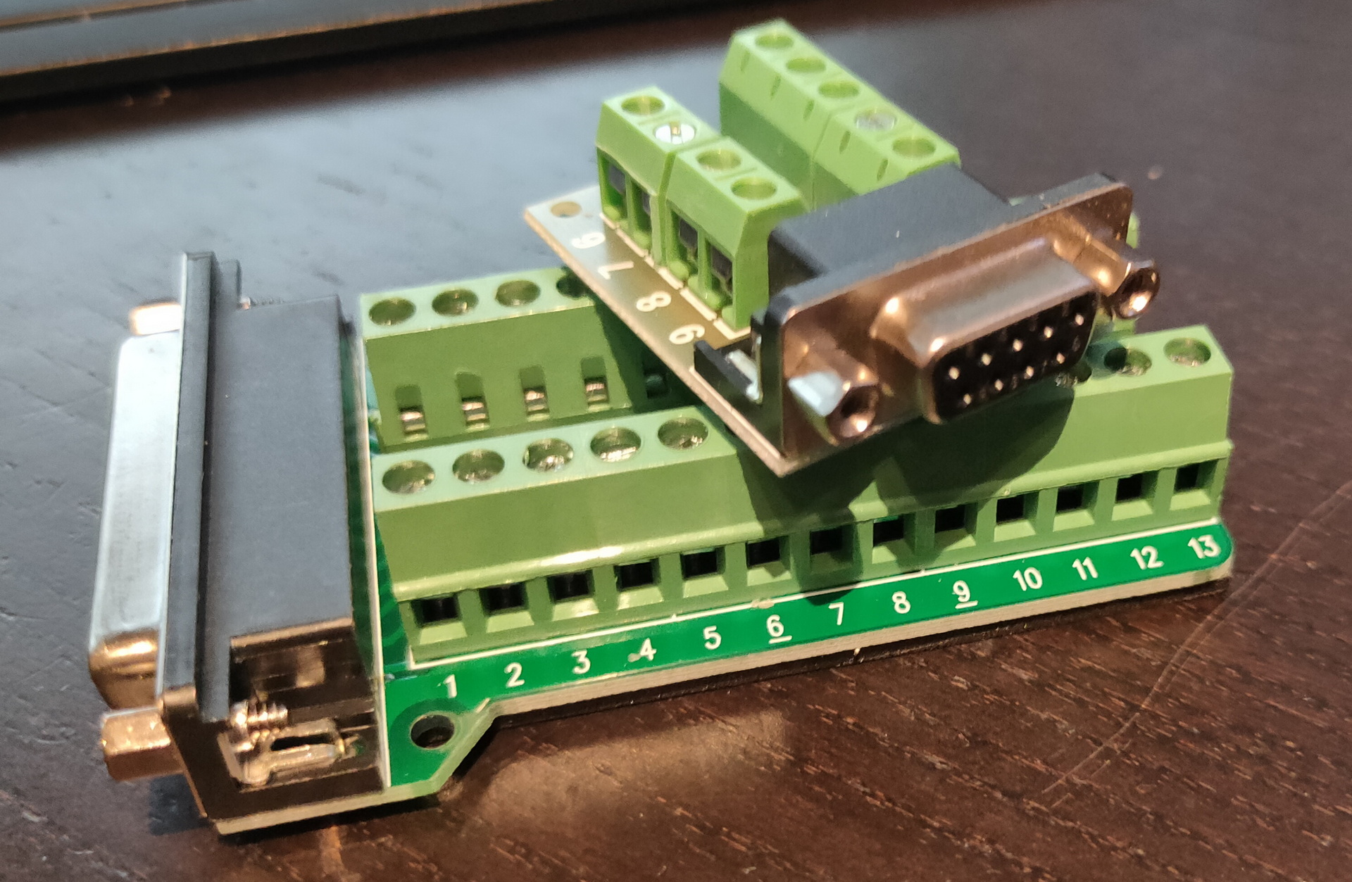
In post https://www.henriaanstoot.nl/2022/11/25/disk-troubles-or-missing-old-skool-hardware/ i mentioned the serial connectors i’ve bought to connect the Laser XT to my Workstation to transfer files.
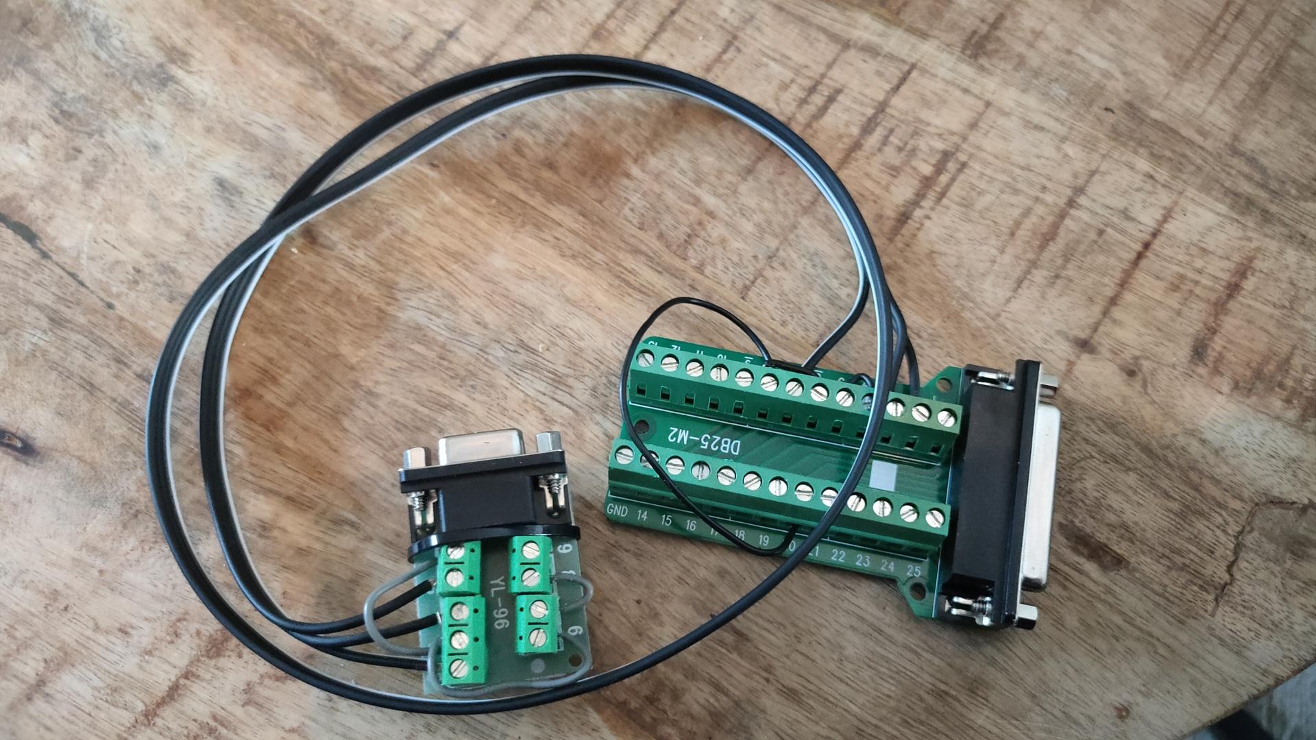
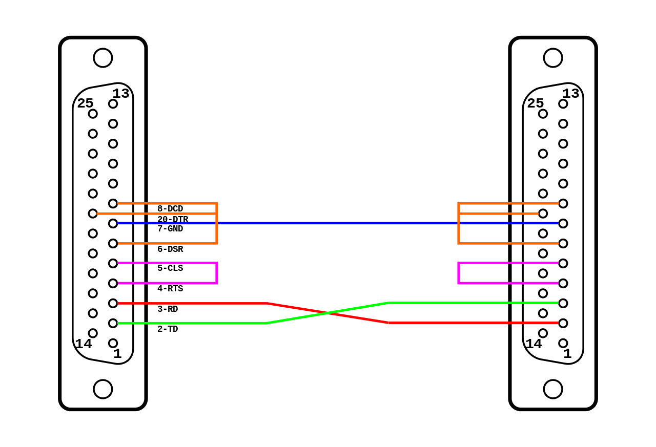
The null modem i’ve made is like mentioned on https://en.wikipedia.org/wiki/Null_modem
I’ve used the loopback handshaking using 3 wires. ( Only using a DB25 and a DB9 on the other end )
So i configured the Linux side as follows.
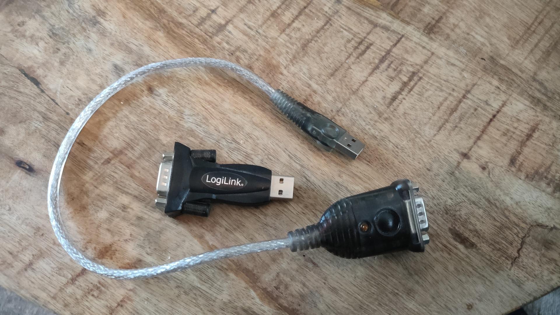
I’ve tried two usb to serial converters.
Both when trying on windows 10 are not supported any more
Dec 14 17:34:40 zspot kernel: [ 1082.299607] usb 1-4: pl2303 converter now attached to ttyUSB0
sudo stty -F /dev/ttyUSB0 9600
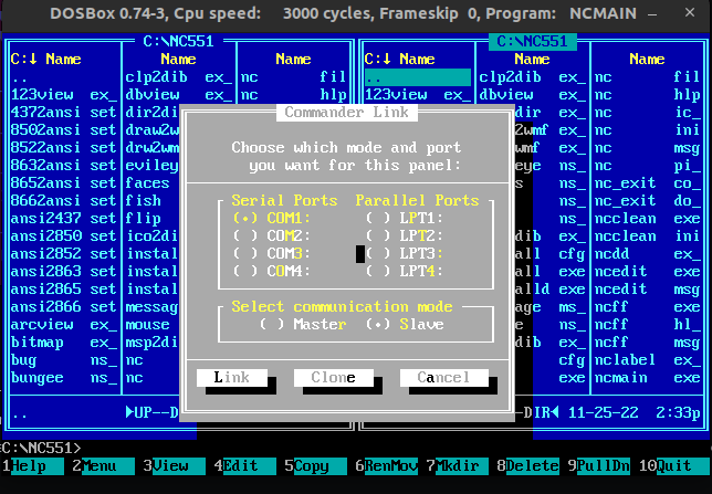
Then i start dosbox. To enable a com port i have to enter:
serial1=directserial realport:ttyUSB0
Starting Norton Commander and selecting COM1
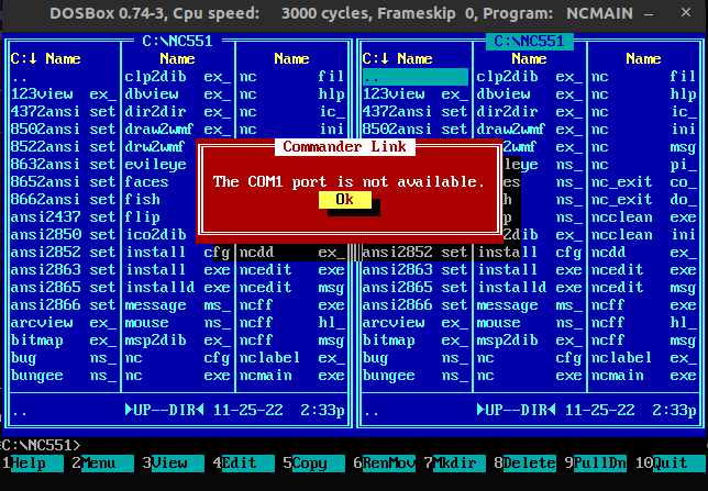
After a few seconds i got this ..
What else is there to check? At least i’ve still got the Flux Engine!
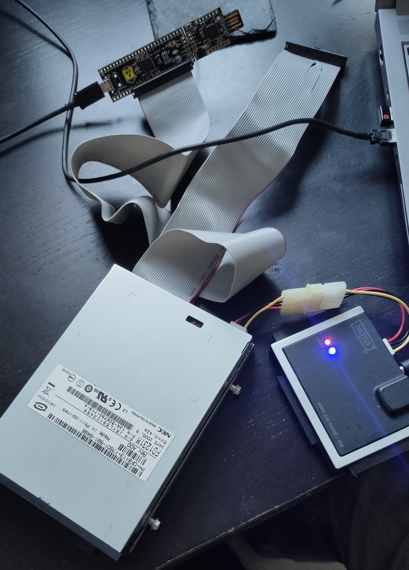
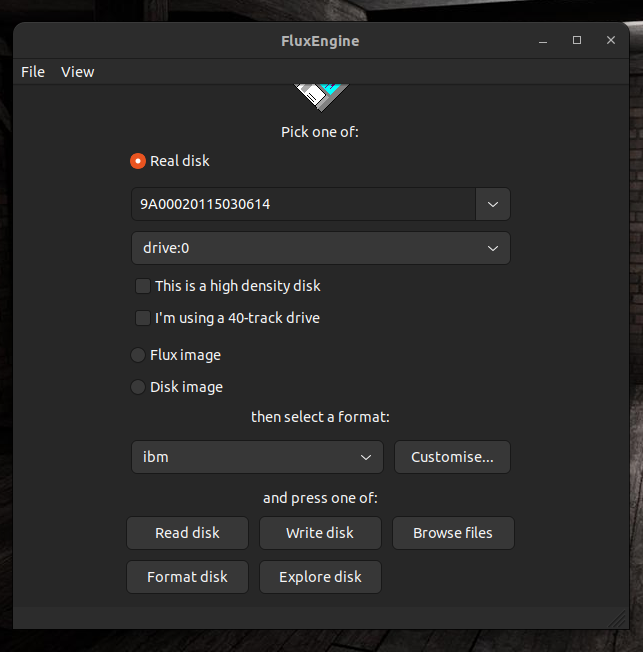
And found this! The fluxengine https://github.com/davidgiven/fluxengine
An open source project using a small controller board. “Flashing” some software on the board and soldering a pinheader was easy. When connecting a flat cable and a floppy drive, you end up with a device which can read many formats. Including dos 1.44/720 and amiga.
Nice package it came in
Using the power from a sata/ide harddisk adaptor
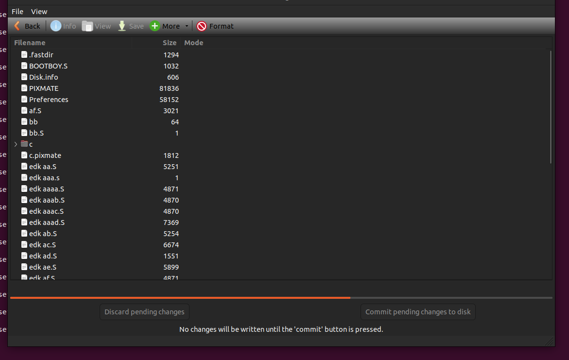
Reading and writing a MSDOS disk, no problem. Imaging an amiga disk .. easy!
You need to compile some software, but it was well documented
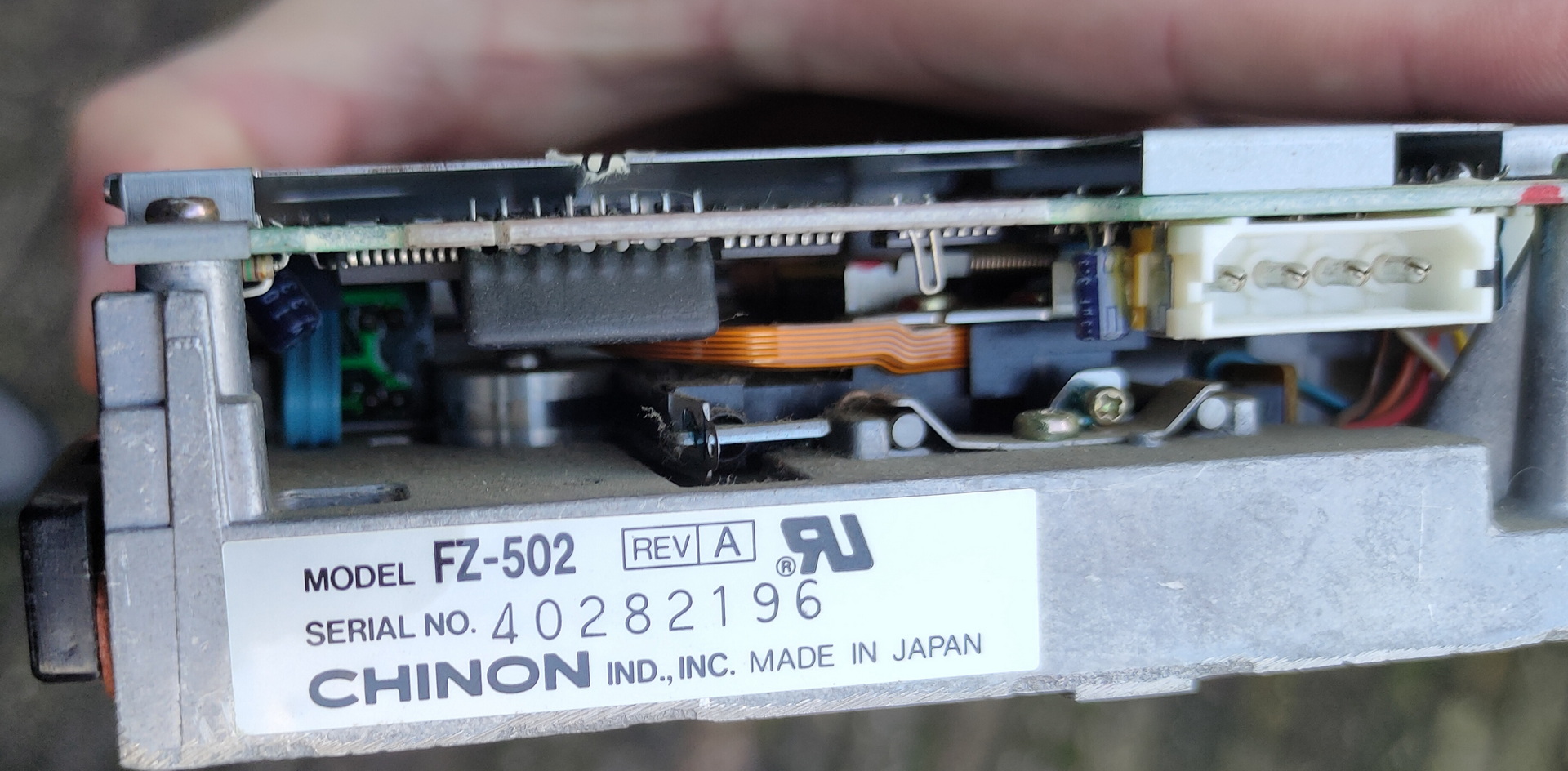
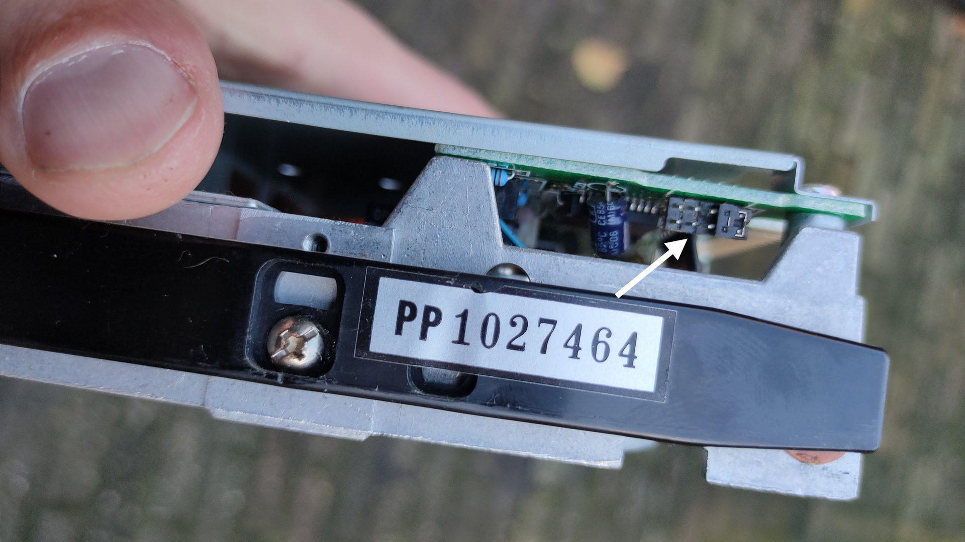
I bought a XT Laser/3 a while ago. And i wanted to get my old programs running on it again.
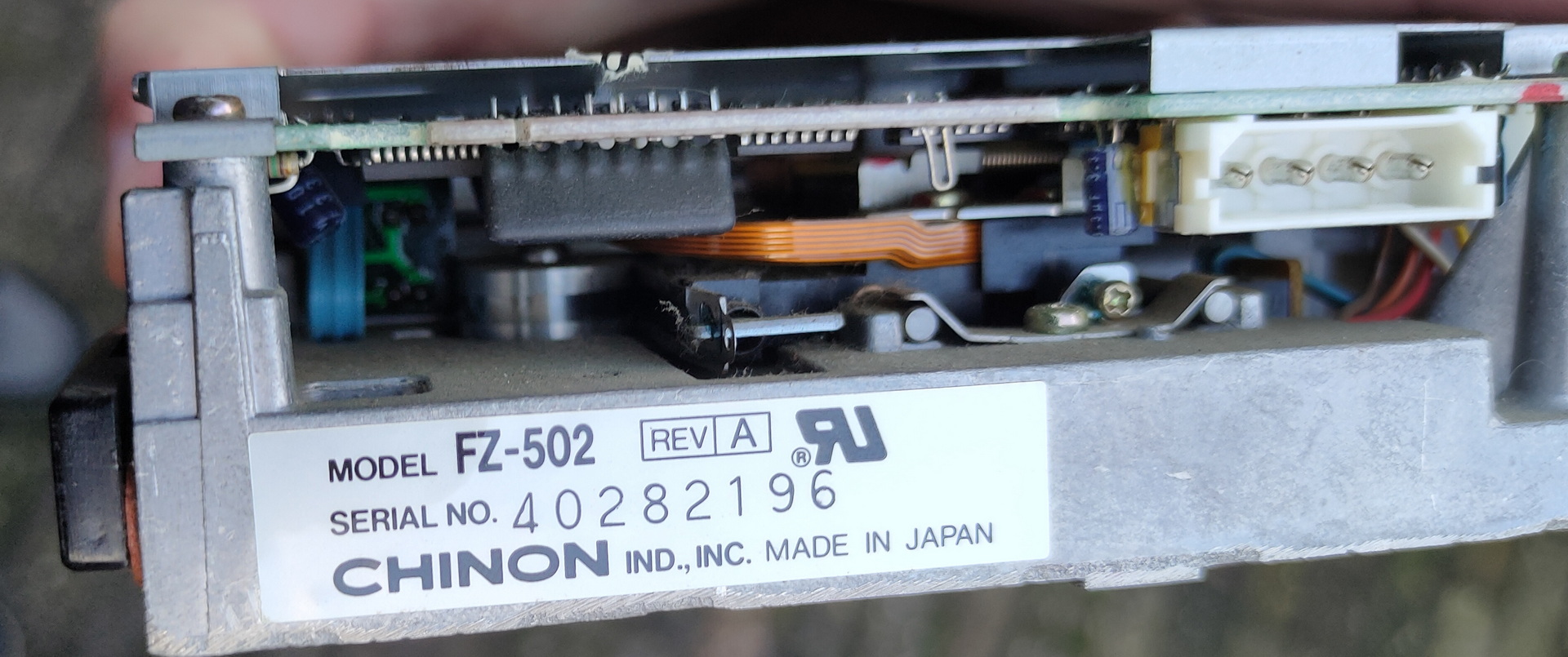
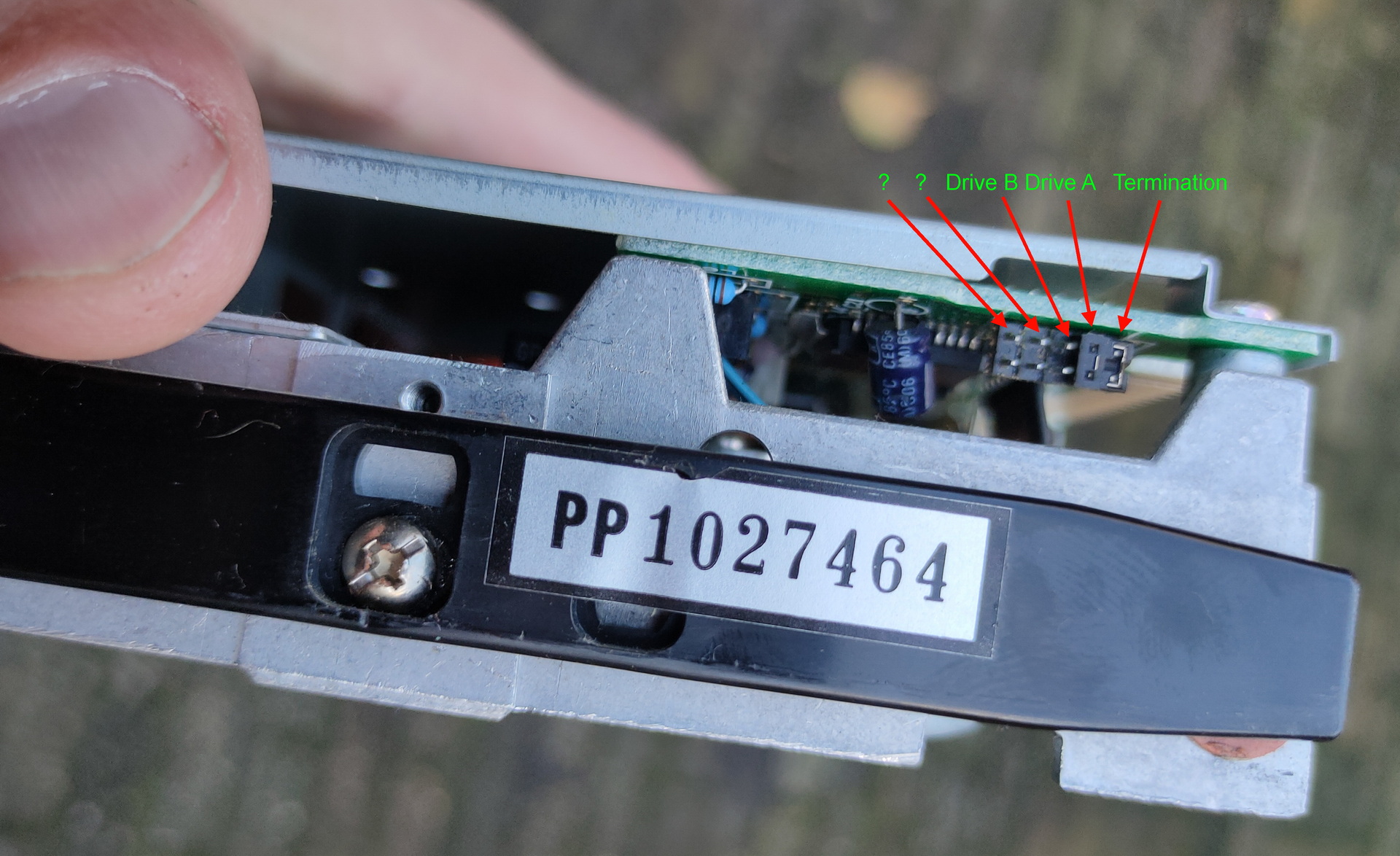
One of the disk i found was a 5.25 inch boot disk which should contain a boot demo i’ve made in the past with Edk. But it is the secondary drive in this system. Those old machines lack a bios you can change. And change A: for B: for example. Some machines had a program which could alter boot settings. (not this one) So i was playing with jumpers and dipswitches on the motherboard. ( Drive select / Termination / drive before or after the twist in the flatcable. )
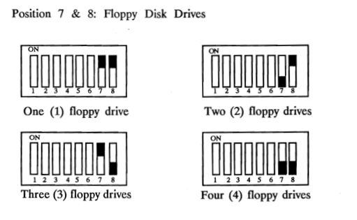
Dipswitches on the motherboard
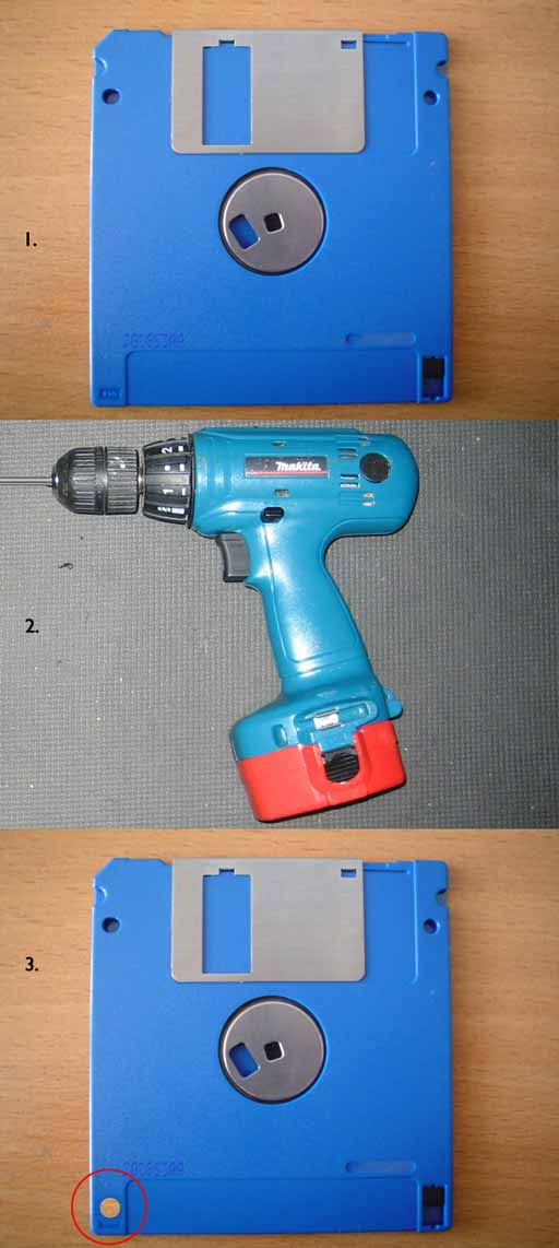
Wellll leave the boot order for now, i needed to get software on the machine using floppy’s. I could not find empty HD disks (1.44MB which i wanted to use) So i took a DD disk and a drill ..
(Image from the internet)
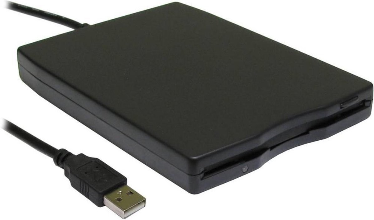
I bought an external usb floppy drive.
Now i have everything to get my programs on the msdos machine.
EXCEPT ….
Diskette didn’t work in the drives. So i bought new old stock diskettes online.
Now i have everything
WRONG again
Formatted 1.44 disk in USBfloppy drive .. OK Read in 3.5 drive on the MSDOS machine .. NOT OK Check drive in MSDOS machine .. is 1.44MB .. OK … check floppy controller in MSDOS machine .. NOT OKAY (720kb is 300kbits per second and 1.44 HD 500kbits per second) So i’m limited to 720kb due to the controller ..
Can the USB Floppy drive read/write 720kb disks .. NO! ( A cheap series made with drives only supporting HD disks )
Alternatives? .. Serial maybe, there is Norton Commander on the MSDOS machine so i could use “link”
Do i still have a USB-RS232 sub-d cable ? YES! Nullmodem cable? NO Make a null modem cable .. i’ve made those before .. BUT no sub-d connectors.
I’ve been throwing away too much in the past.
Now i have to buy those things again:
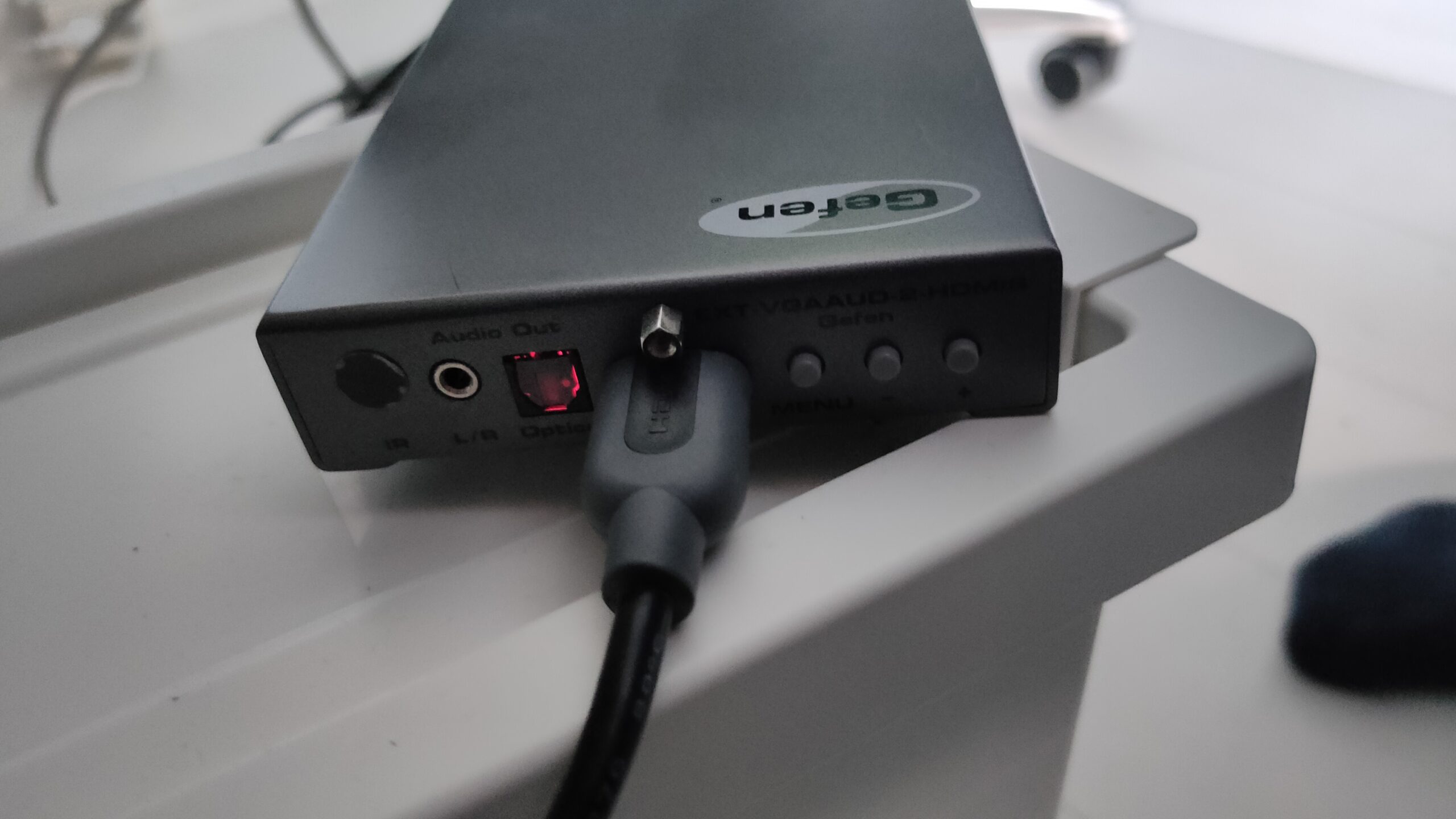
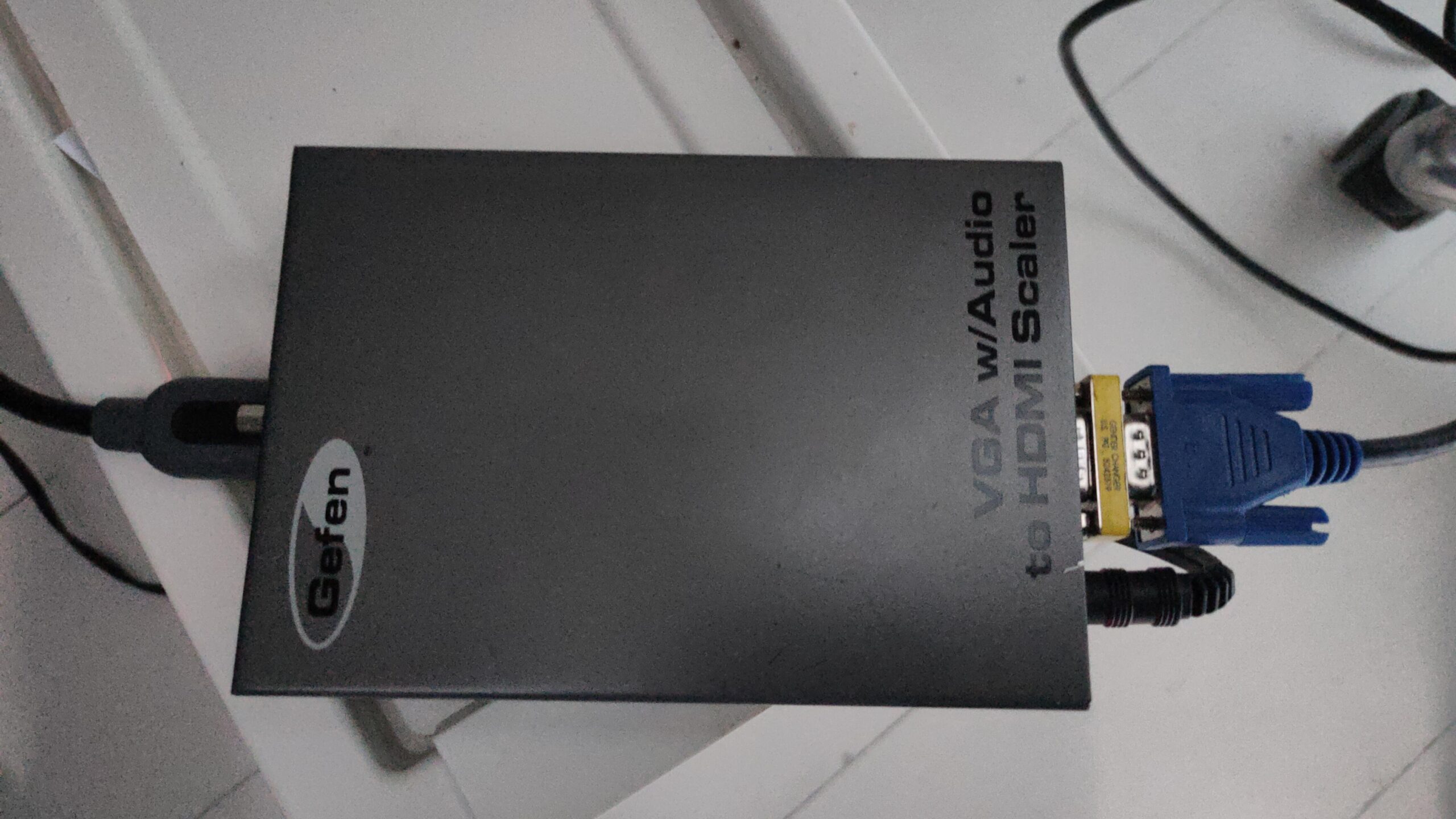
VGA – 8bit ISA – have 2 now Floppy drive – have one for 1.44 8bit soundblaster compatible – TODO Nullmodem – well i’ve bought connectors for those
While playing with MuseScore…. (Typesetting some scores for Pipes and Flute)
This came in: WOOOT
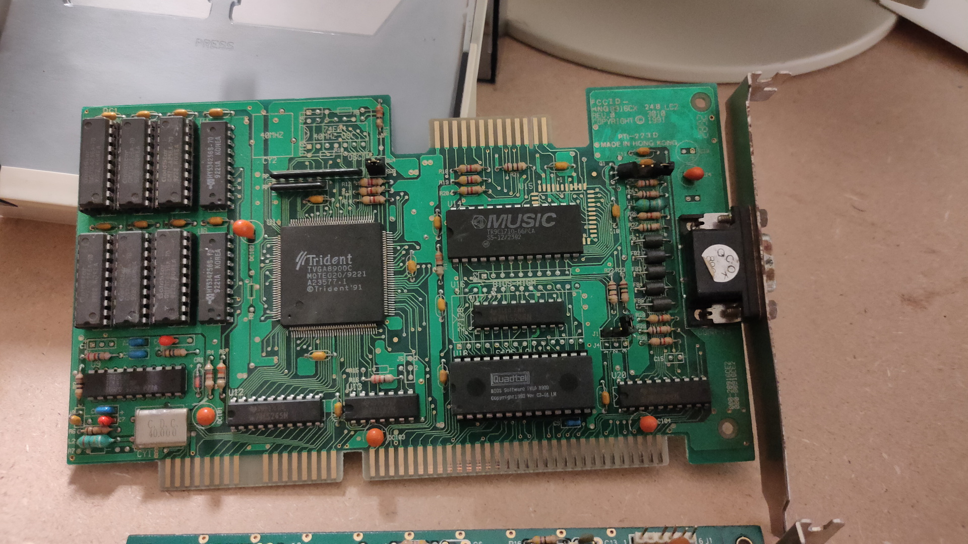
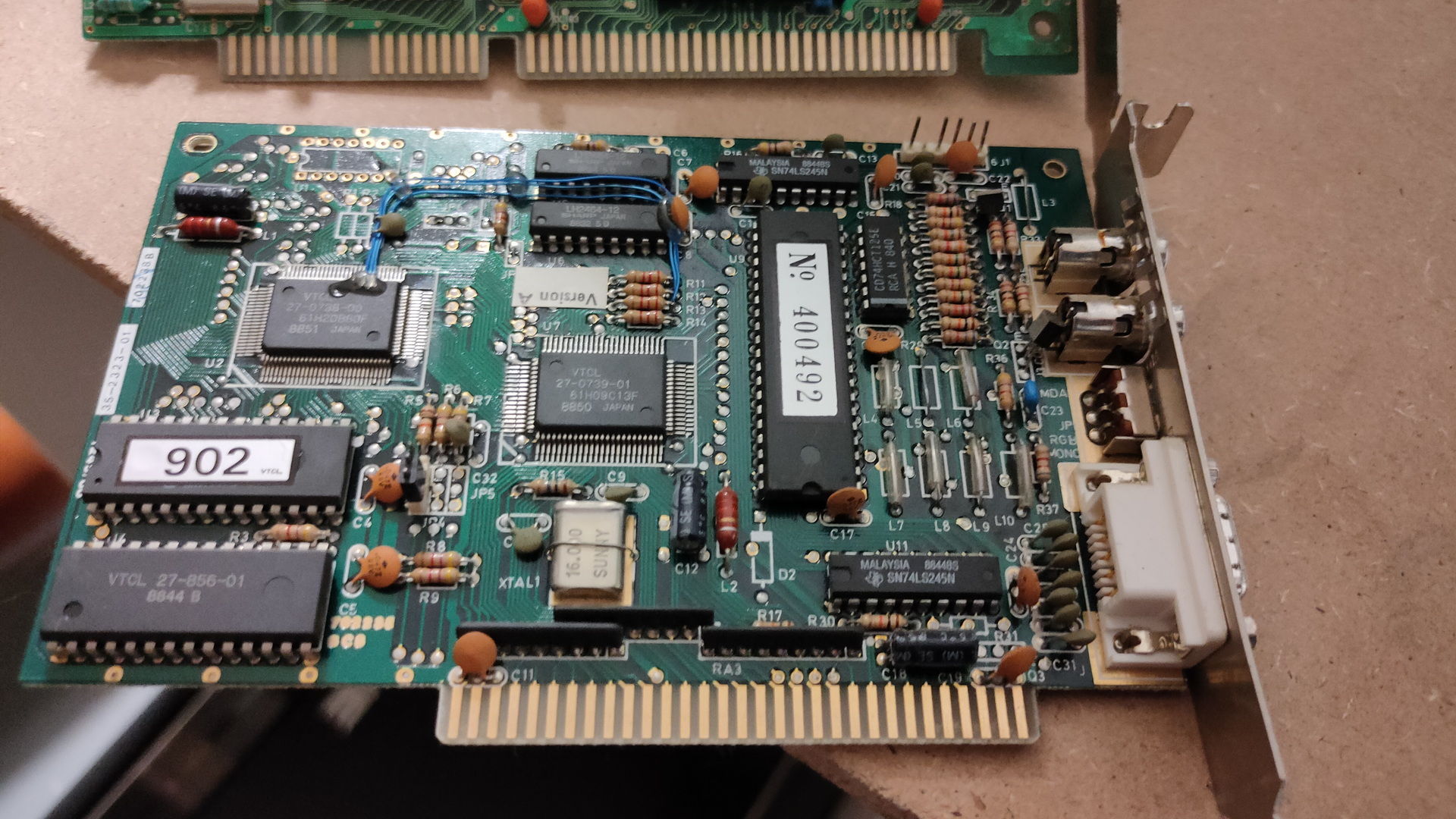
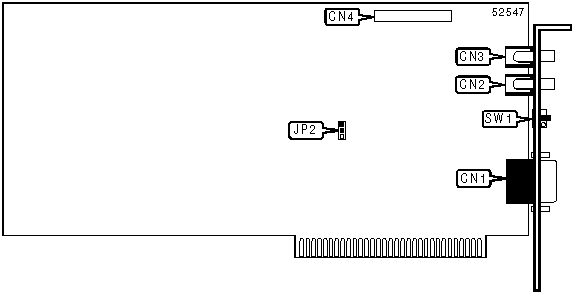
Trident 8900C (1024 x768 max 512Kb)
This is a Trident VGA card. While having a 16bit ISA connector, it can work in a 8bits ISA slot.
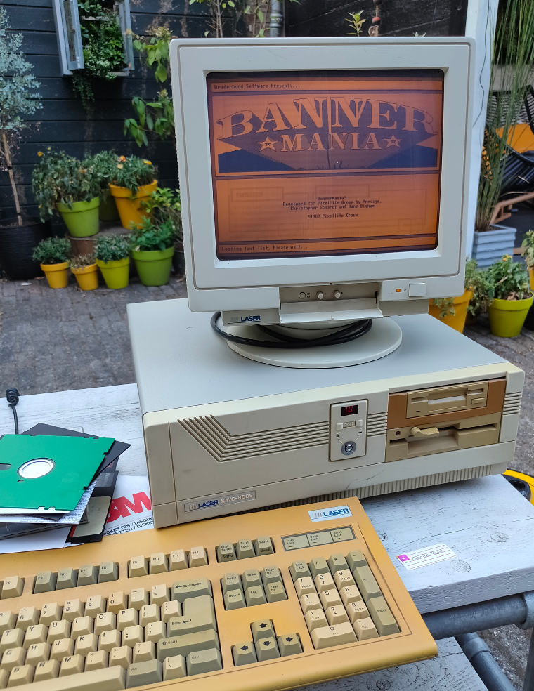
A while ago i bought a Laser XT/3, that’s the one my parents had. This is where i did a lot of assembly programming on. It’s a 8086 cpu, 640K and has a Hercules/CGA graphics card.
I found loads of assembly files and i want to see if i can get it running again. While some code was written for hercules, ( That’s the monochrome image you see in the example above ) and a few for EGA (4 colors).
Most of it was written for VGA. Probably on a later machine like a 80386?
But i know there are vga cards for 8 bit msdos computers, and i found one. ( This one is even autodetect, so no jumpers to figure out)
So i’ve put this card in the machine, turned it on, and it works! I’ve got only 2 examples living on the harddisk of the machine, both black and white … 🙂 I have to search for interesting code in hundreds of files.
Some friends of mine, picture was taken from an amiga genlock digitizerThe intro pages of a “amiga emulator” WHERE is the rest??? (end is a cga starfield demo)
And a boot demo, which was able to start from a bootsector, went into a graphic mode and ran a demo with sound. Edk wrote a sector loader for this. I have some 5.25 inch floppy disks, labelled boot demo. So i wanted to try this today … I needed to change the boot order, so i went online to search for jumper settings.
I see a led when it tries to boot, but my disks are probably formatted 720Kb instead of 360Kb, which this drive is.
So …. TODO!
Find a 720Kb floppy drive (5.25 inch), and sort through my code! There is a 8bit soundblaster compatible soundcard that i bidding on online, hopefully i’ll get it
Assembly and modes
I wasn’t sure how to sort the assembly code into Hercules and VGA compatible, but i used this table (There are also extended modes for higher resolutions)
mode 0x00
text 40×25 gray
mode 0x01
text 40×25 16 colors
mode 0x02
text 80×25
mode 0x03
text 80×25 16 color
mode 0x04
graphics mode (CGA) 320×200
mode 0x05
graphics mode (CGA) 320×200
mode 0x06
graphics mode (CGA) 640×200 (B/W)
mode 0x07
text 80×25 Hercules
mode 0x0F
graphics mode 640×350? gray
mode 0x10
graphics mode 640×350?
mode 0x11
graphics vga 2 colors
mode 0x12
graphics vga 16 colors
mode 0x13
graphics 320×200 256 colors
# Set VGA mode
    mov ax,13h
    int 10h         ;screen 320x200 256 colours

# Exit VGA mode
    mov ax,3
    int 10h         ;screen  80x25 text
    mov ax,4c00h
    int 21h         ;back to DOS
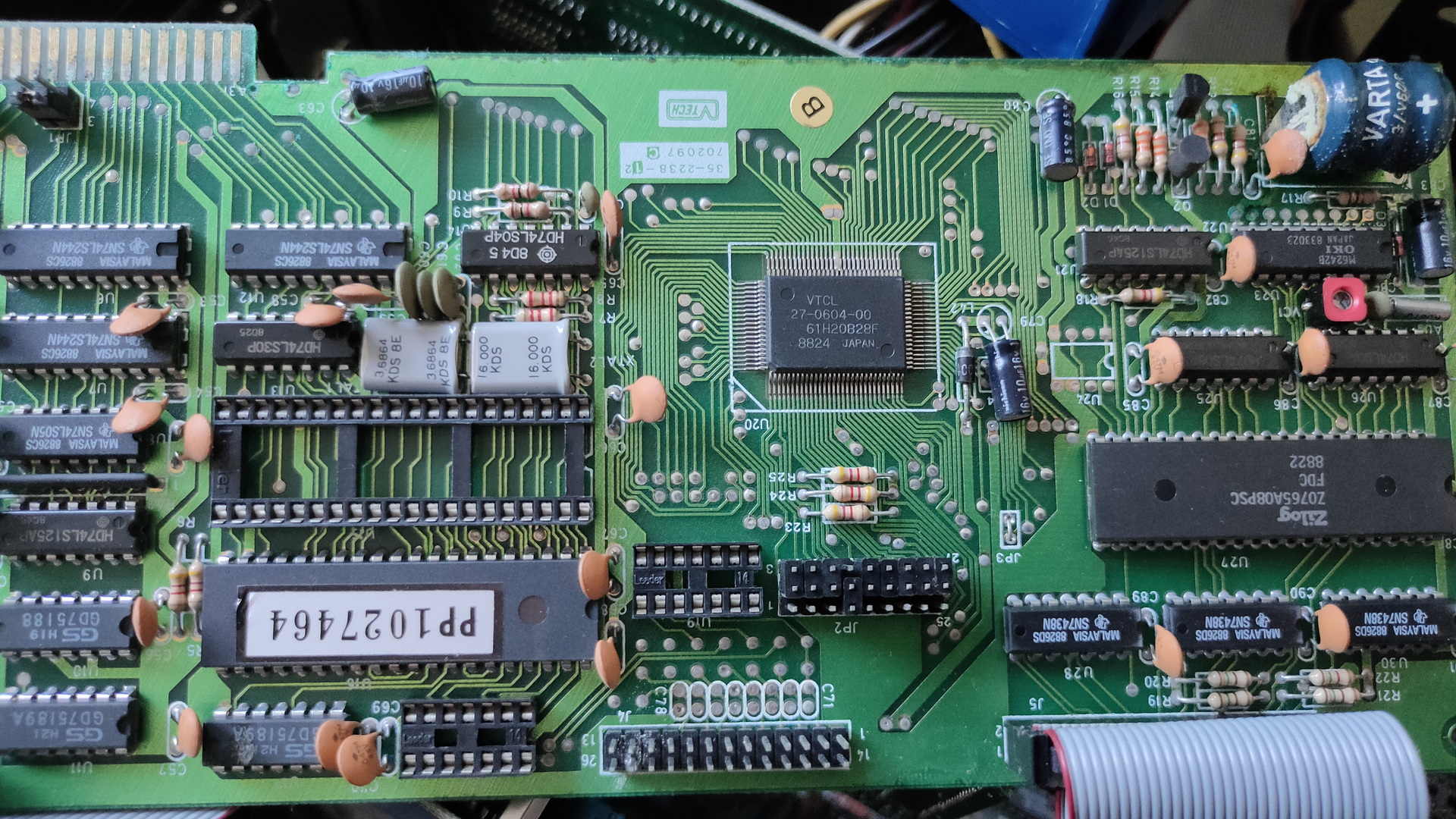
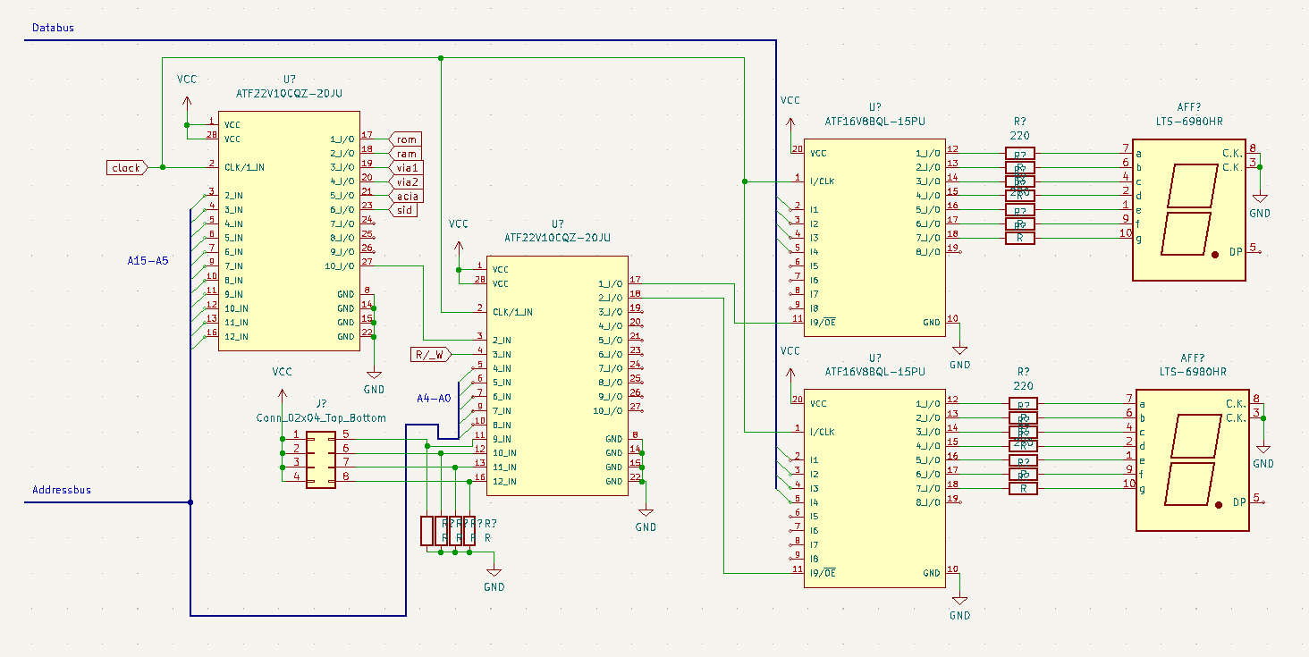
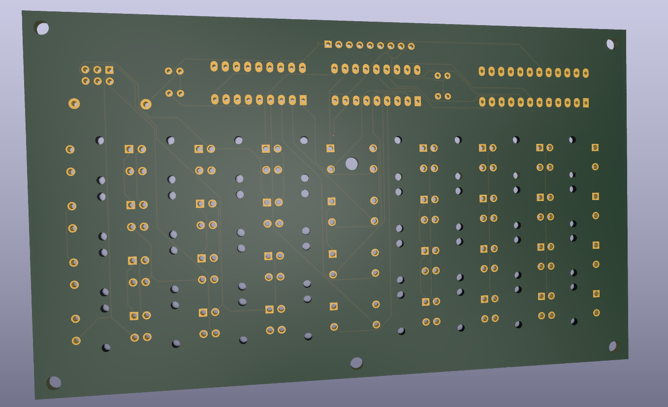
Sometimes when i’m writing code i want to know what’s happening. For example when i’m working on the display, there is maybe no output. With the above example i can write to address $01F0 (example address), and it will display on the 7 Segment displays.
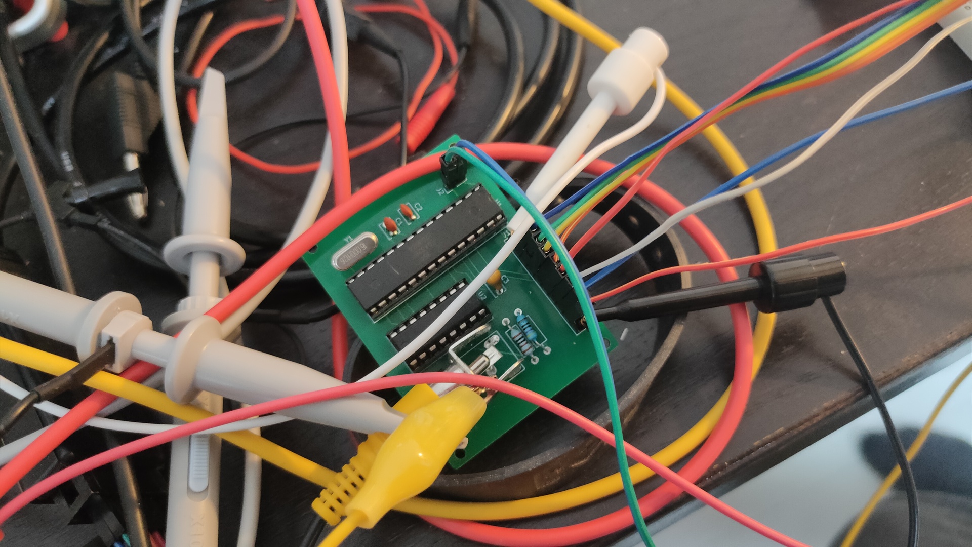
Upperleft PLD is my address decoder, which has been running for a while now.
Secondary PLD adds the rest of the Addressbus lines, and gives me the opportunity to select in a range of 16 addresses, using jumpers/
The two smaller PLD’s latch the databus data when addressed. AND decodes a nibble to 7-Segment output for 0-9A-F. (There are apparently no chips available which do A-F)
I’m going to add the PLD code when everything works. Let me know if you like the idea.
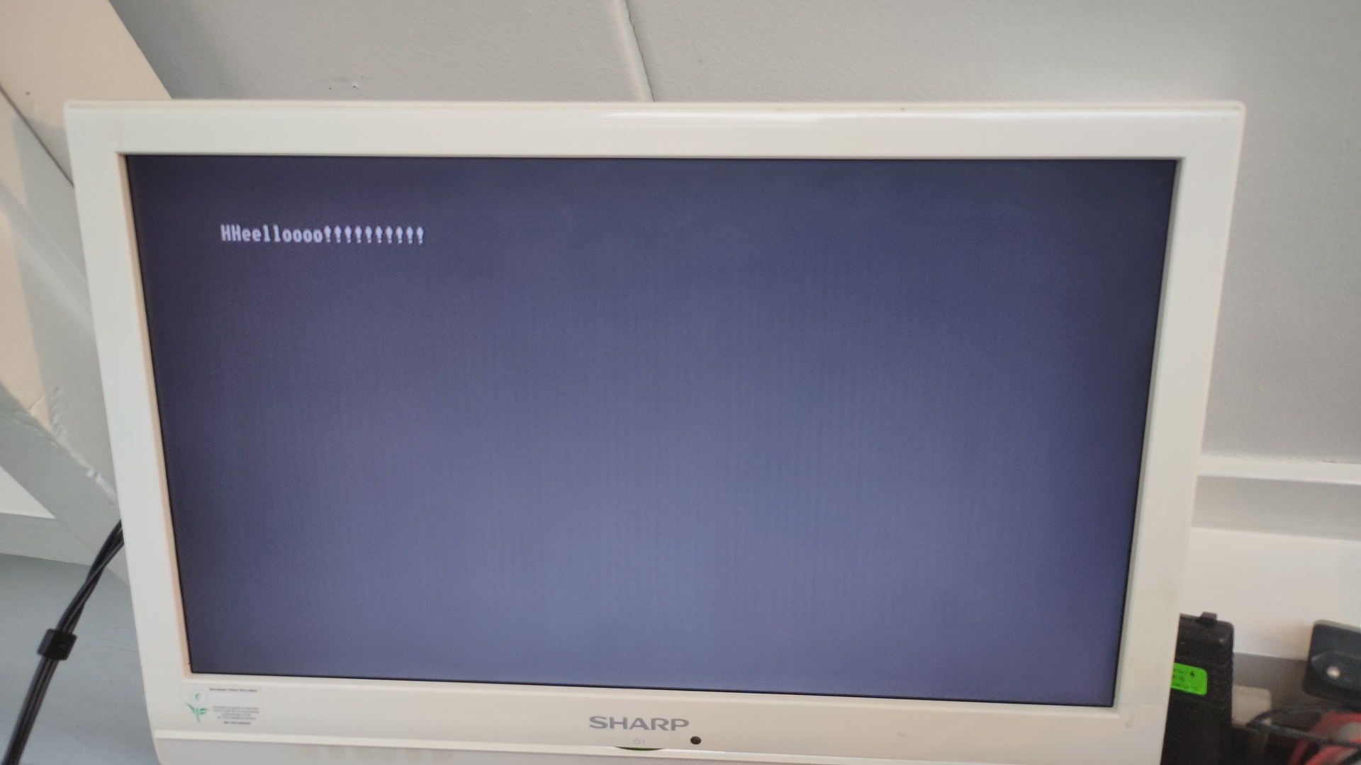
No more sync issues! (see post https://www.henriaanstoot.nl/2022/10/19/composite-video-with-atmega328p/ )
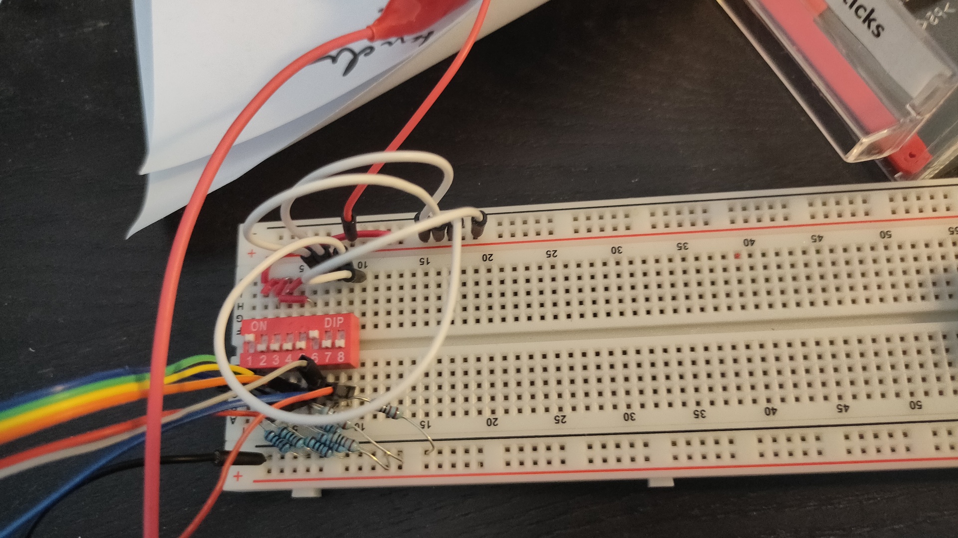
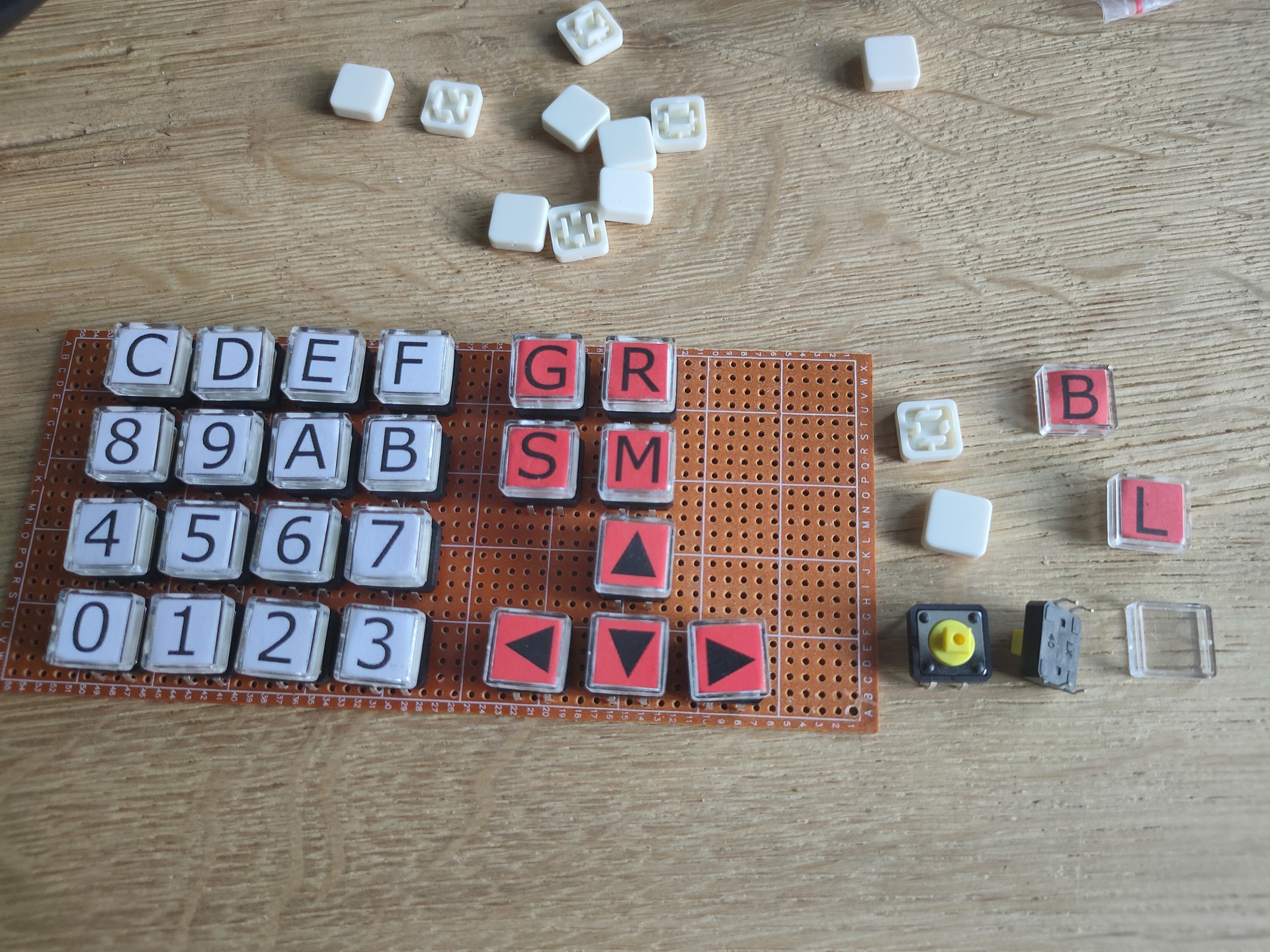
There are some duplicate characters, the input device below does not have a proper debounce method.
My temporary input device (note hex 21 is a “!” character)
No need to fix the debounce, the dipswitches are temporary. This will be controlled by the VIA 6522 chip.
UPDATE 20221108 (Connected to second VIA)
PORTB = $5000
PORTA = $5001
DDRB = $5002
DDRA = $5003
clock = $e0

E  = %10000000
RW = %01000000
RS = %00000000

  .org $0200

reset:
  ldx #$ff
  txs

  lda #%11111111 ; Set all pins on port B to output
  sta DDRB
  lda #%10000000 ; Set top pin on port A to output
  sta DDRA
  lda #$00  ; reset bit
  sta PORTA
  sta clock

  ldx #0
print:
  lda message,x
  beq printborder
  jsr print_char
  inx
  jmp print

loop:
  jmp loop

message:
        .db 0x01,0x04,0x0C,0x0E,0x10,0x0F,0x08
        .db 0x05,0x0a,0x0a
        .db 0x05,0x0b,0x0b
        .asc "Composite Video 6502 - 20221108"
        .db 0x0E,0x11,0x0F,0x0C
        .asciiz " With 2 pixels "

waitloop:
  pha
  tya
  pha
  ldy #$ff
back:
  dey
  bne back
  pla
  tay
  pla
  rts

print_char:
  sta PORTB
  jsr waitloop
  jsr waitloop
  lda clock
  eor #%10000000
  sta clock
  sta PORTA
  jsr waitloop
  lda clock
  eor #%10000000
  sta PORTA
  jsr waitloop
  rts
Control codes as from : http://searle.x10host.com/MonitorKeyboard/index.html
Video display control codes:
Hex (Decimal) and meaning
01 (01) - Cursor home (Standard ASCII)
02 (02) - Define cursor character (2nd byte is the curs character, or 00 to turn off) <--New for 3.0
03 (03) - Cursor blinking
04 (04) - Cursor solid
05 (05) - Set graphics pixel (next two bytes = x,y) <--New for 3.0
06 (06) - Reset graphics pixel (next two bytes = x,y) <--New for 3.0
08 (08) - Backspace (Standard ASCII)
09 (09) - Tab (Standard ASCII)
0A (11) - Linefeed (Standard ASCII)
0C (12) - Clear screen (Standard ASCII)
0D (13) - Carriage return (Standard ASCII)
0E (14) - Set column 0 to 79 (2nd byte is the column number) or 0 to 39 for a 40 char line
0F (16) - Set row 0 to 24 (2nd byte is the row number)
10 (16) - Delete start of line
11 (17) - Delete to end of line
12 (18) - Delete to start of screen
13 (19) - Delete to end of screen
14 (20) - Scroll up
15 (21) - Scroll down
16 (22) - Scroll left
17 (23) - Scroll right
18 (24) - Set font attribute for the current line (see elsewhere on this page for details) <--New for 3.0
1A (26) - Treat next byte as a character (to allow PC DOS char codes 1 to 31 to be displayed on screen)
1B (27) - ESC - reserved for ANSI sequences
1C (28) - Cursor right
1D (29) - Cursor Left
1E (30) - Cursor up
1F (31) - Cursor down
20 (32) to 7E (126) - Standard ASCII codes
7F (127) - Delete
80 (128) to FF (255) - PC (DOS) extended characters
There are a lot of old develop boards for all kinds for cpu’s.
These where build to learn machine code programming. Mostly made in the 80’s, and based on populair cpu’s at that time.
I own a some of these SDK’s (System Design Kits)
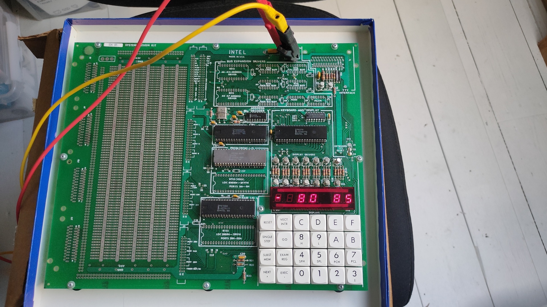
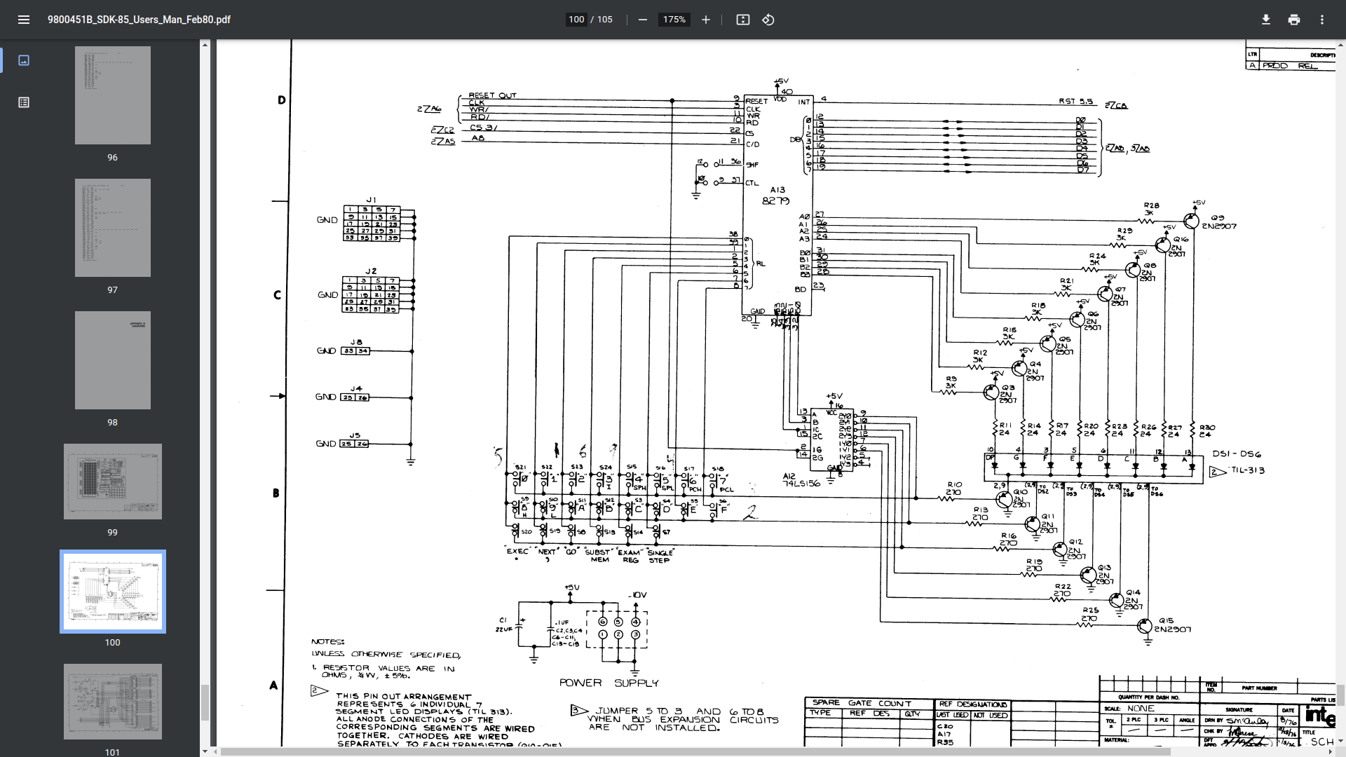
8085 – SDK85 i bought recently 8085 CPU
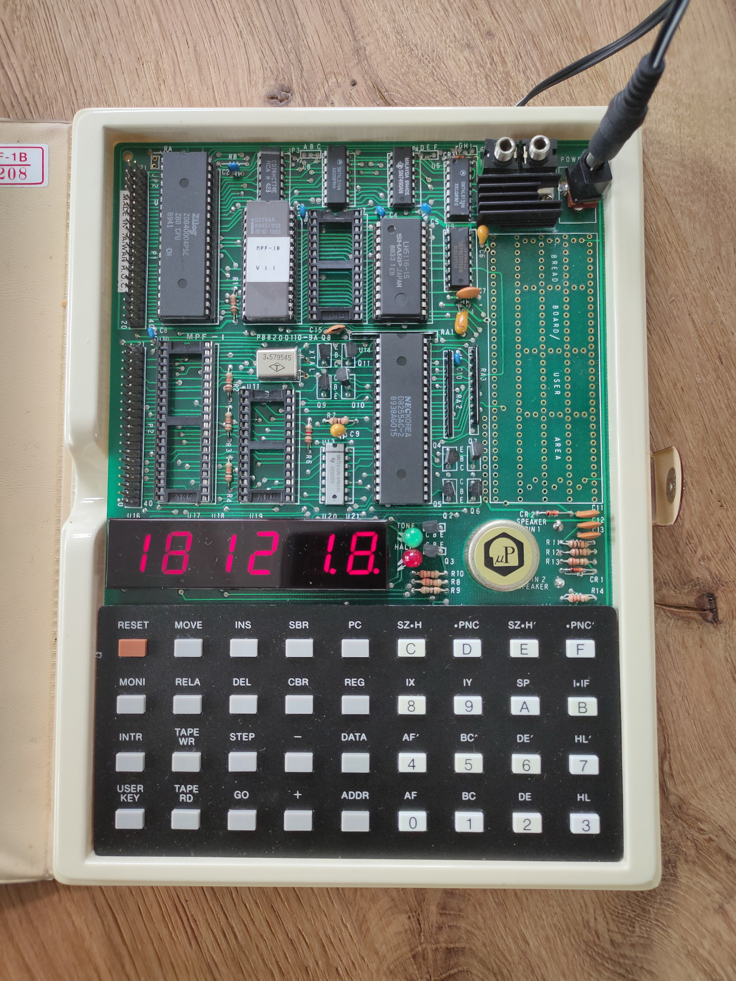
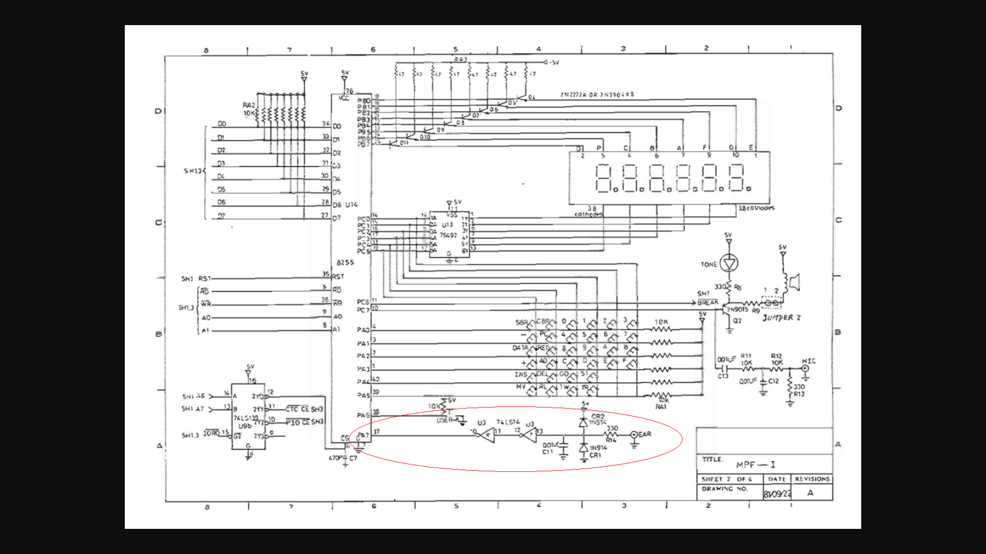
Microprofessor-1 (MPF-1) Z80 CPU
And my own 680x based computer
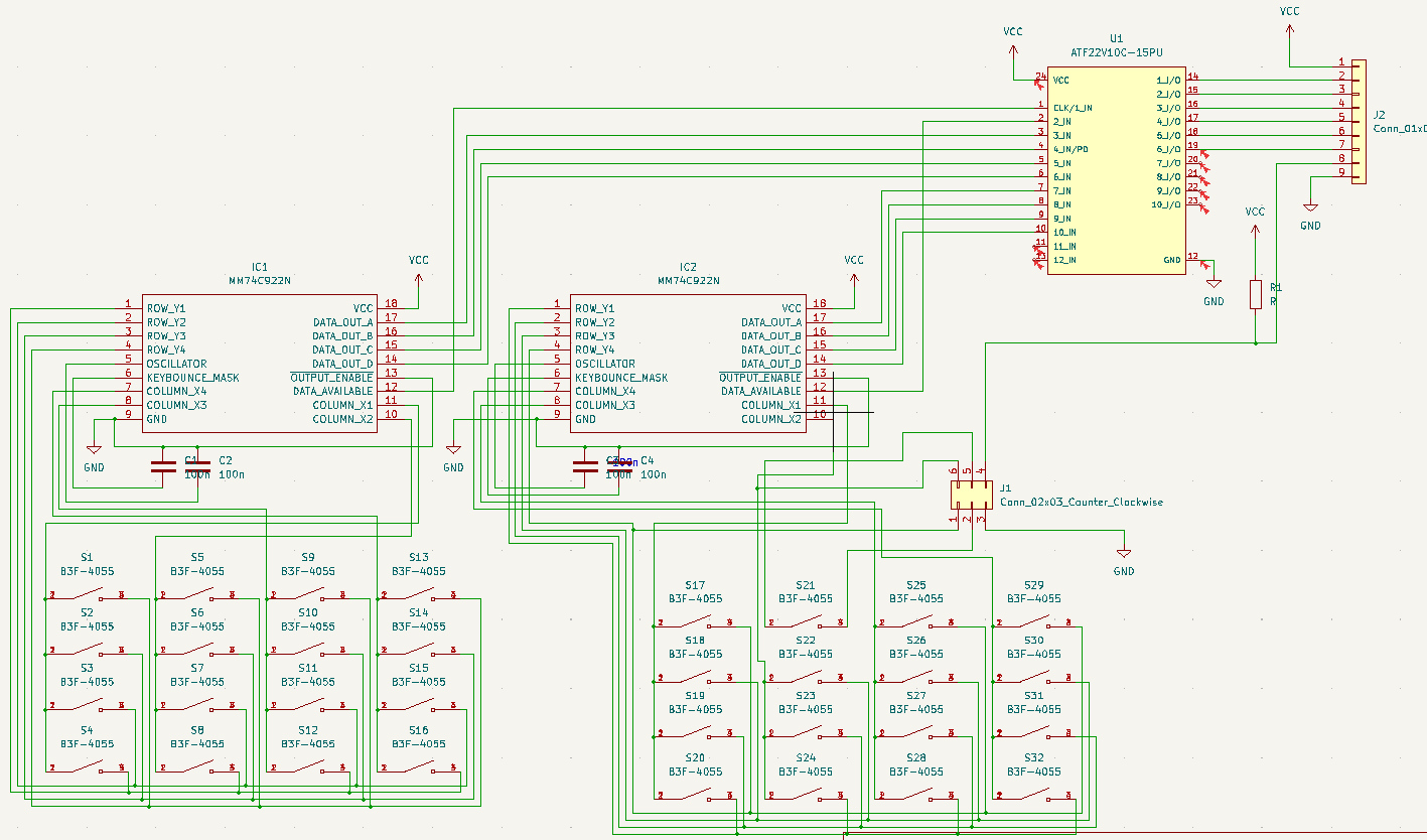
Most of these use a keyboard scanner which is also connected to 7 segment displays.
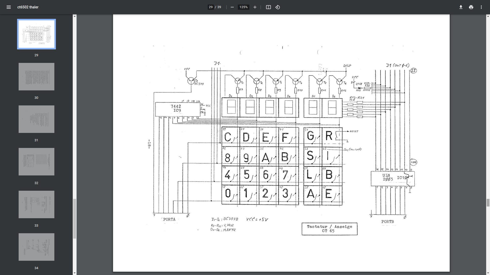
The way they work is practically the same. There is a VIA or PIA. Versitile interface adaptor, or Peripheral interface adaptor. These have two times 8 bits to control devices. When using 4 bits and convert these to 16 lines by using a 75ls145 for example. If you put a counter on those 4 bits, you sequently activate 1 of 16 lines. These lines you can use to scan a keyboard matrix OR display a character on a 7 segment display. These display’s won’t hold the data (and show the character) when not activated. The trick is to update de display fast enough so you don’t see the flickering on/off.
Activate a line and read a byte with the VIA = Reading keyboard row Activate a line and write a byte with the VIA = Display on a segment
These VIA/PIA’s where made with specific timings to match the CPU. 6522/6820/8255
Below you see some different implementations of these keyboard/display combo’s
Thaler 6502 kit
Microprofessor MPF-1 kit (ignore red circle)
SDK85 kit
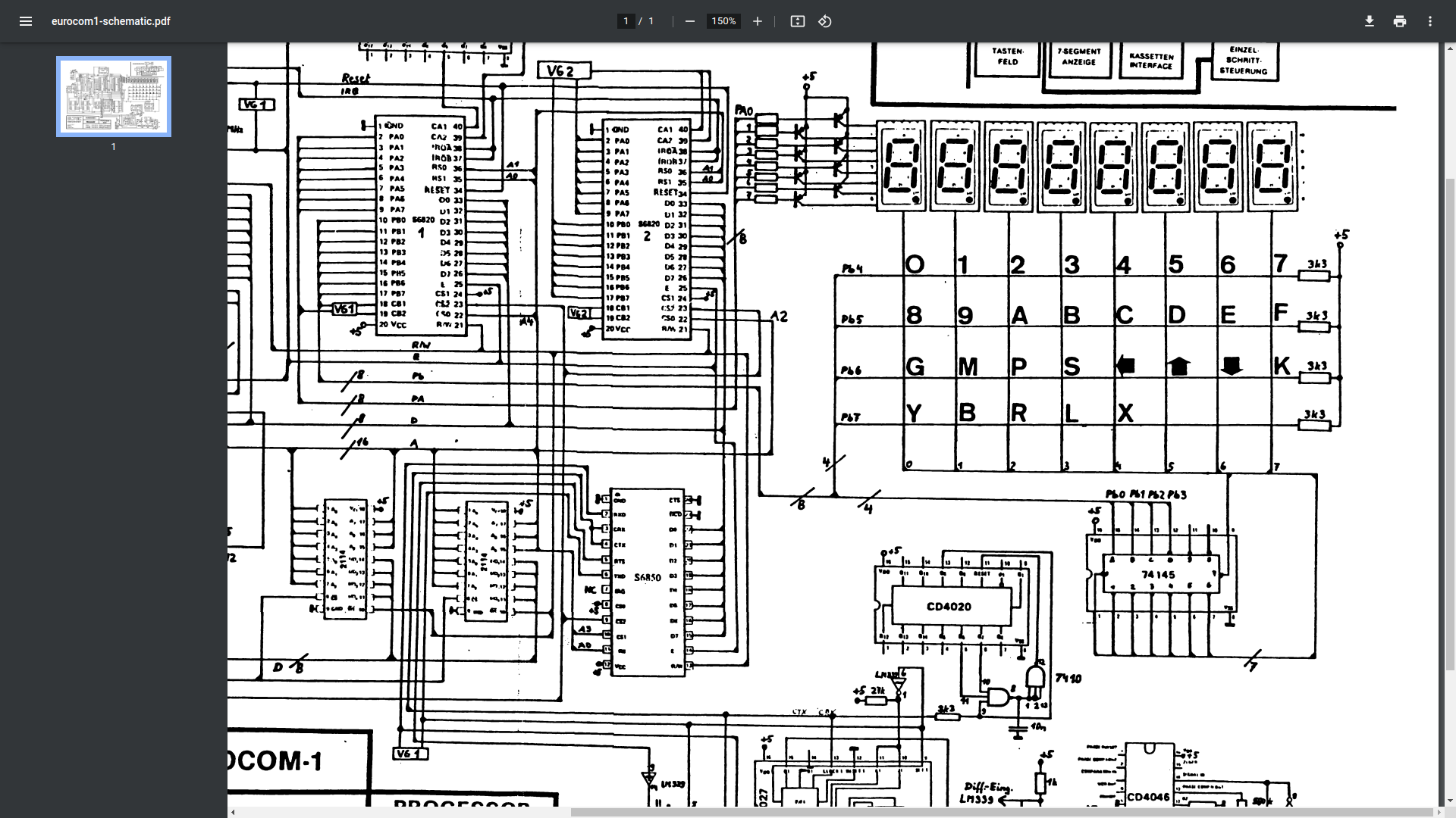
Eltec 6800
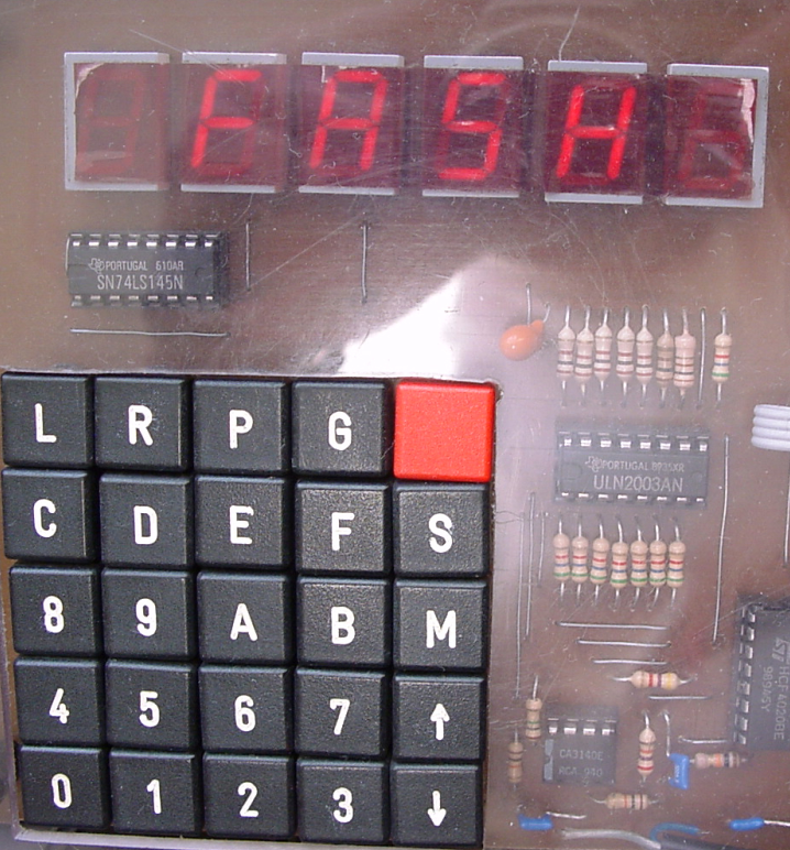
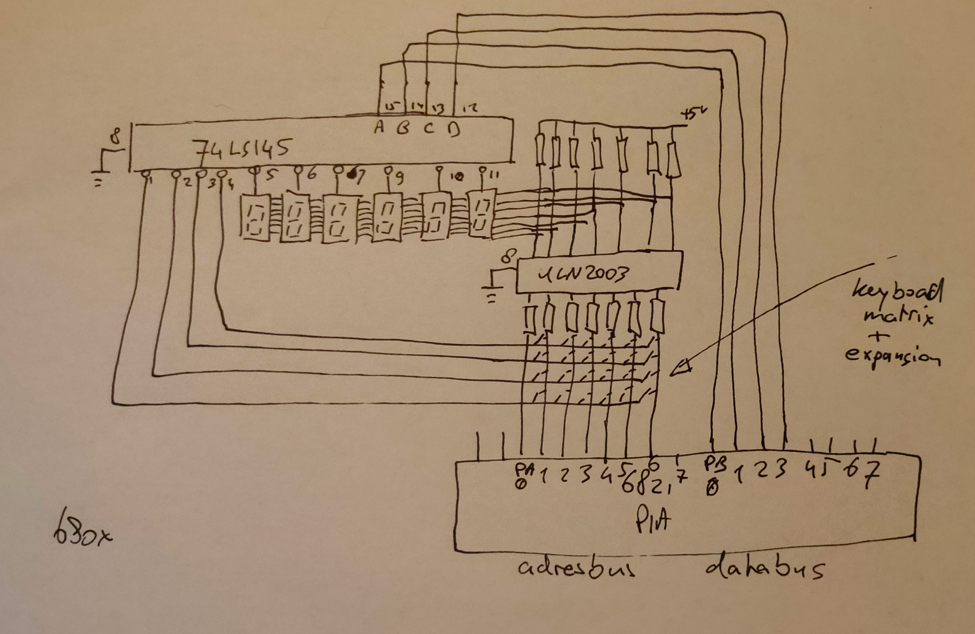
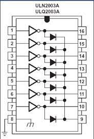
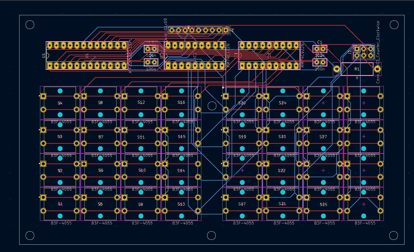
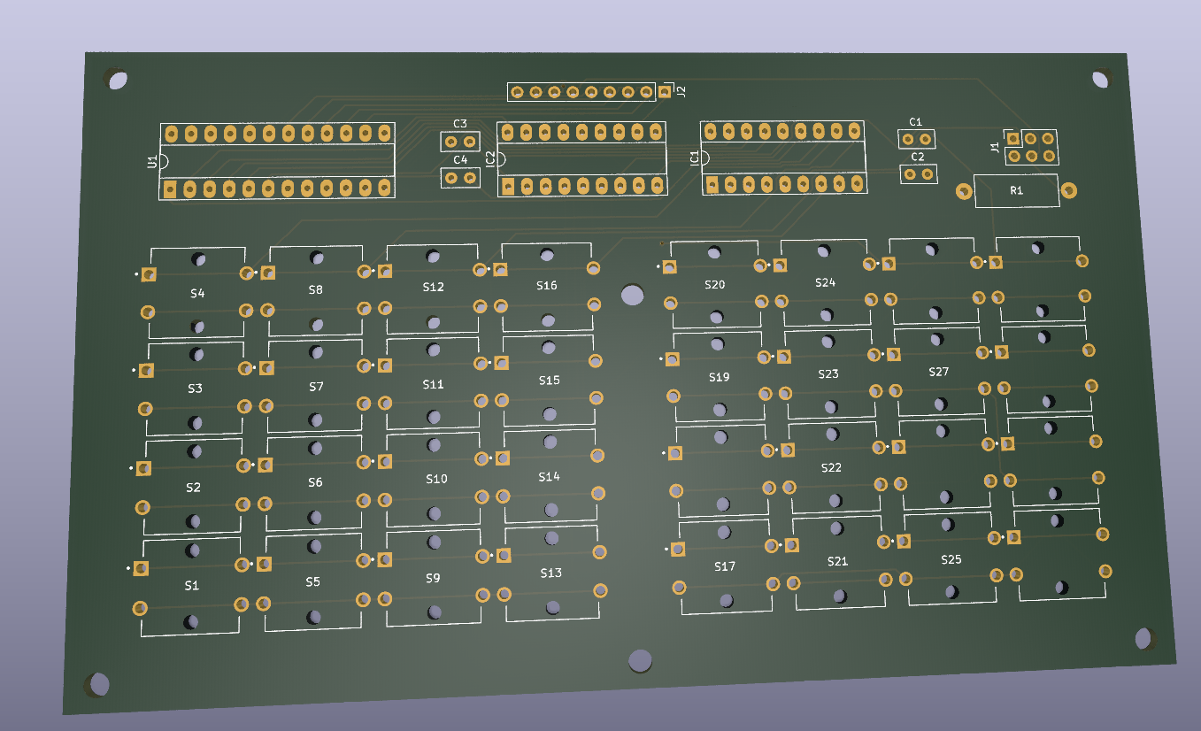
My version using darlington arrays (ULN2003)
When looking at the 8085 version you see transistors being a ULN2003 is a chip with those transistors/amplification enclosed. It doesn´t draw much current from the bus, and diodes protect the way the current flows.