We went to WHY2025 a hackers camp in the Netherlands.
The first time I went was in 1997, with Bigred. Many followed after that. Tyrone, Bigred were also there from our old Crew. Coline joined me several times since 2005.
I joined the Badge team, and was making spacers for the Badges in bulk using my 3D printer. Also made some fancy cases.
CasesSpacers
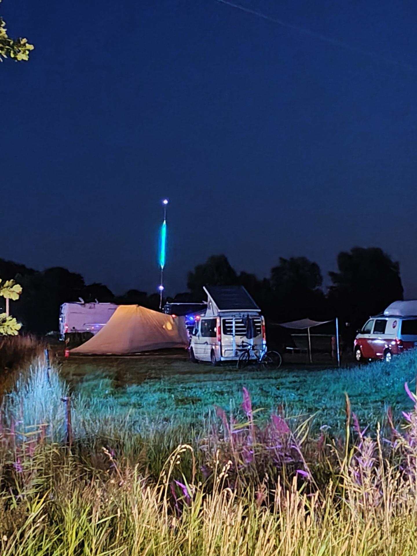
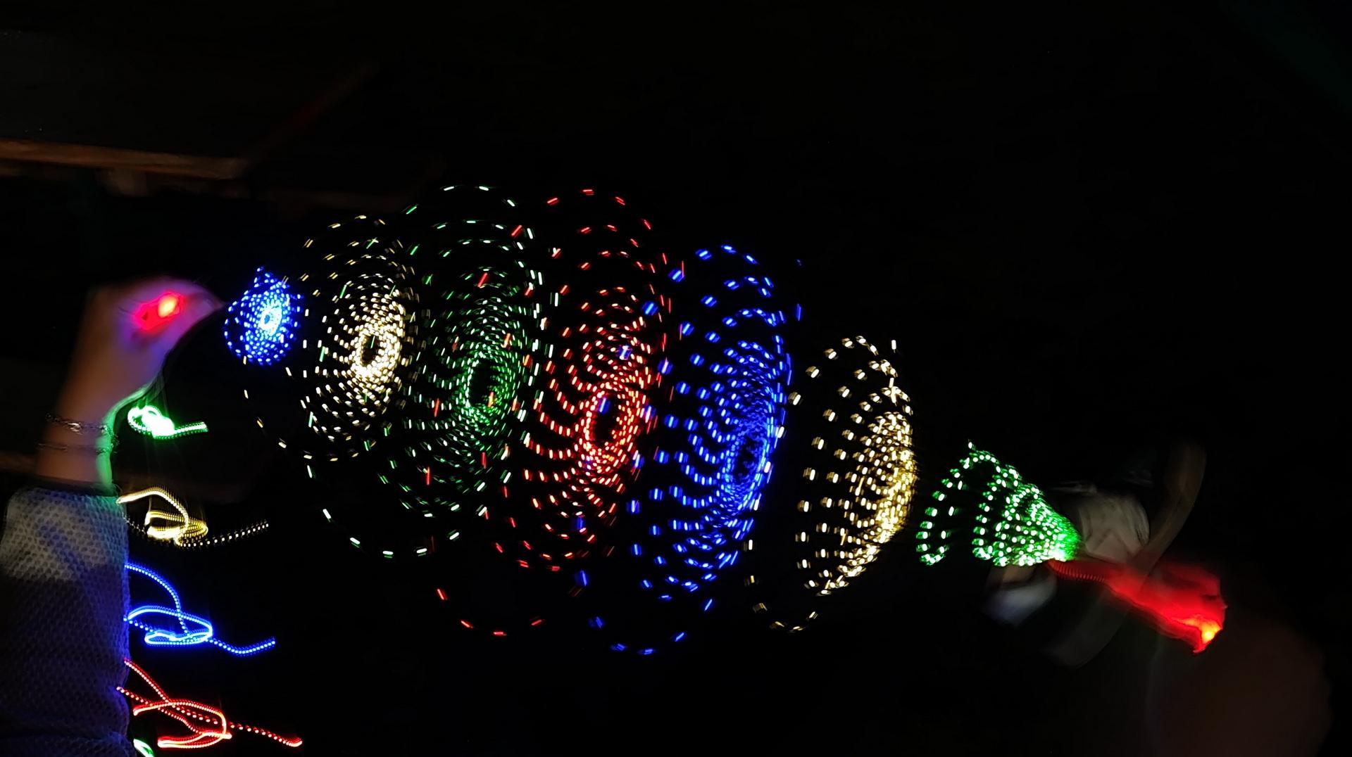
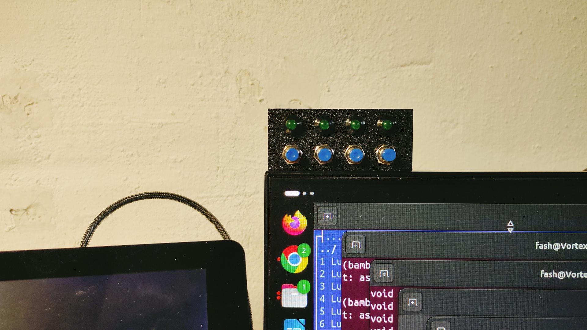
In case of doubt .. more leds!
Our campsite with 7m Led stringMust have more leds!
Nice weather, good friends. New friends. Booze. Food and Hacking. We visited a lot of talks and enjoyed the music. (And fire)
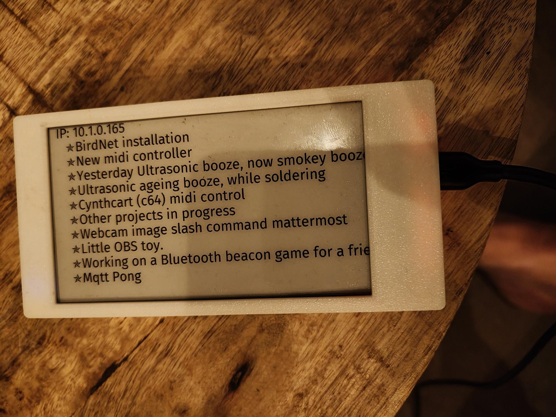
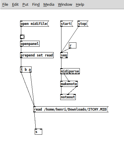
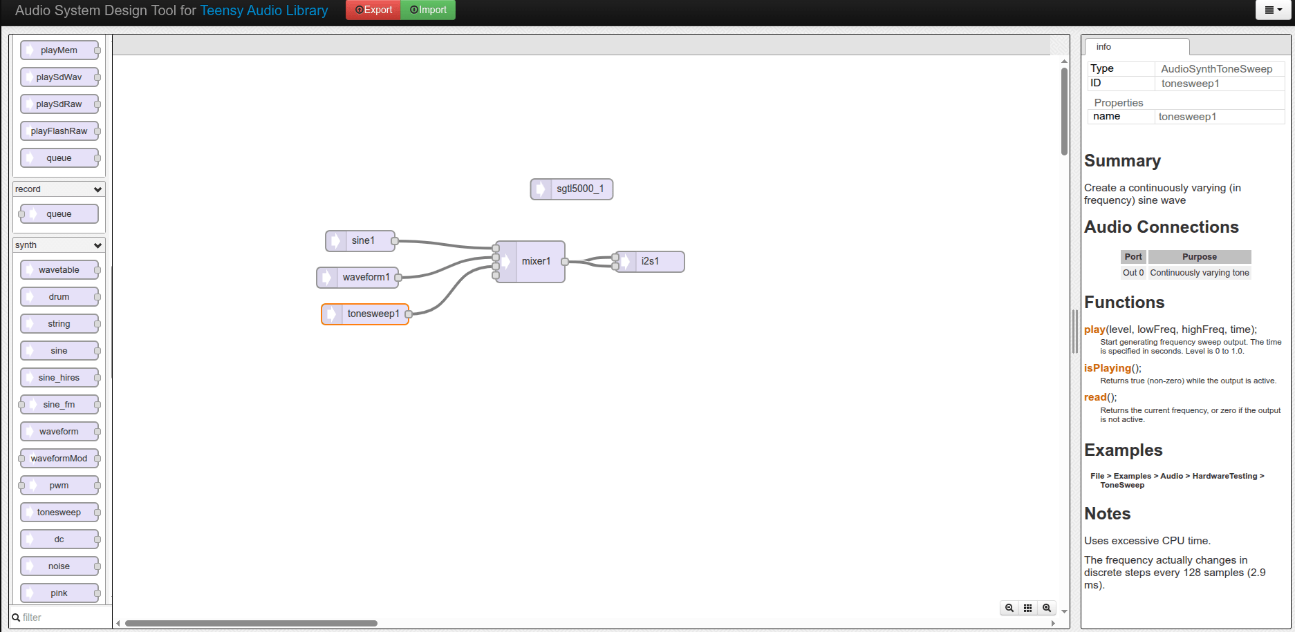
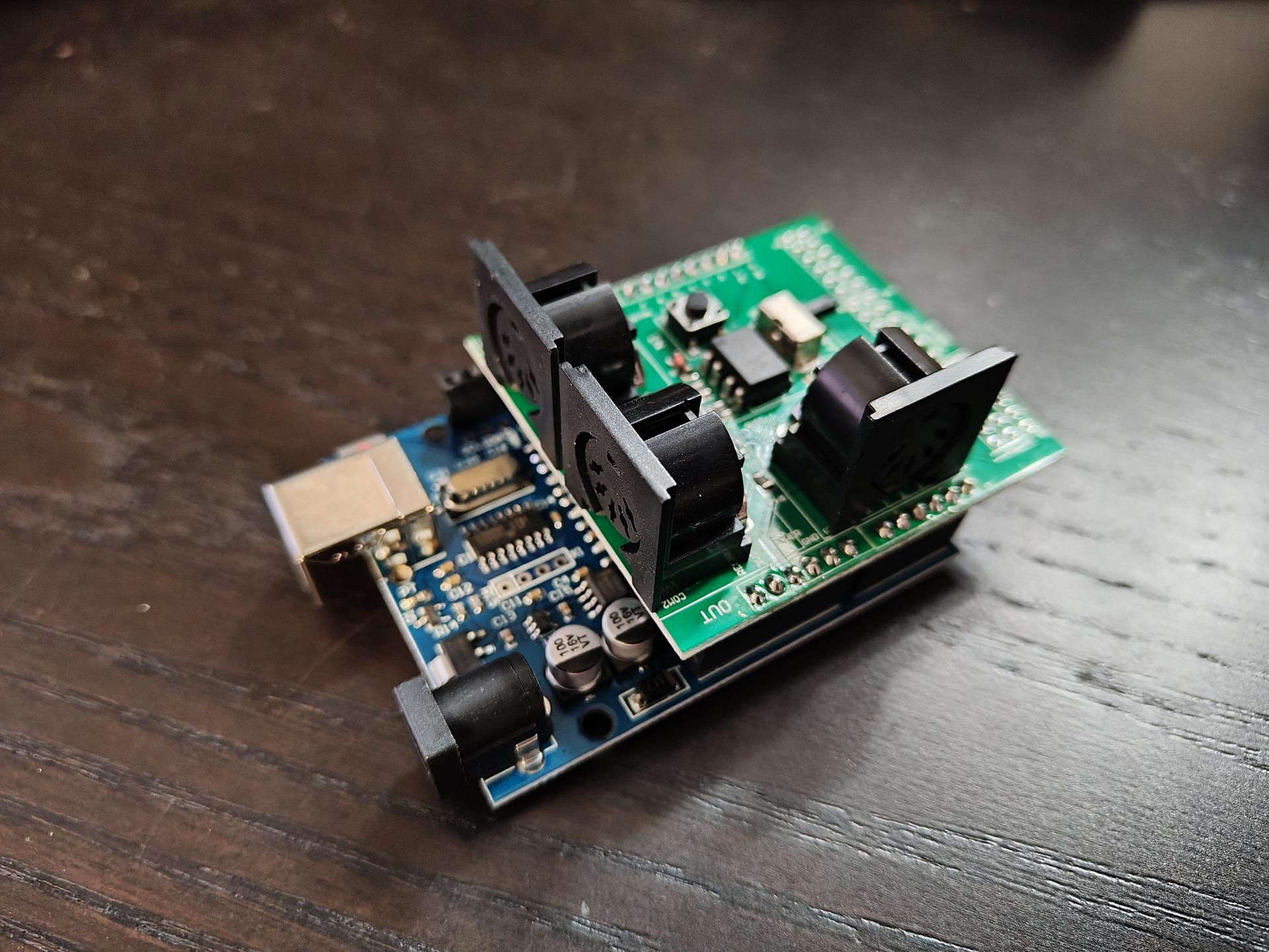
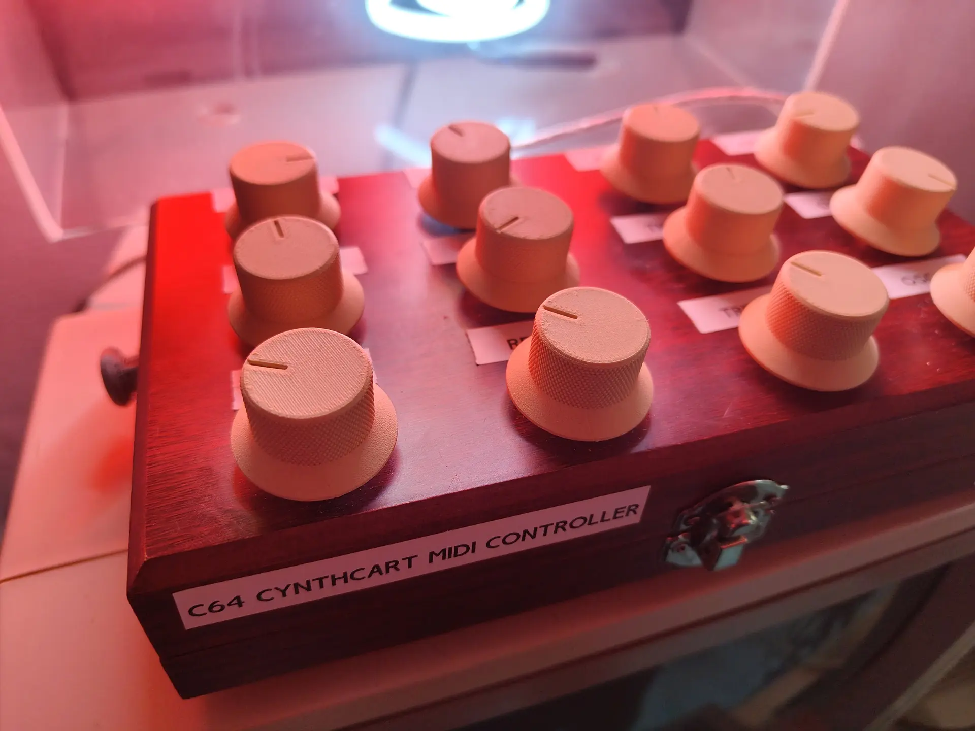
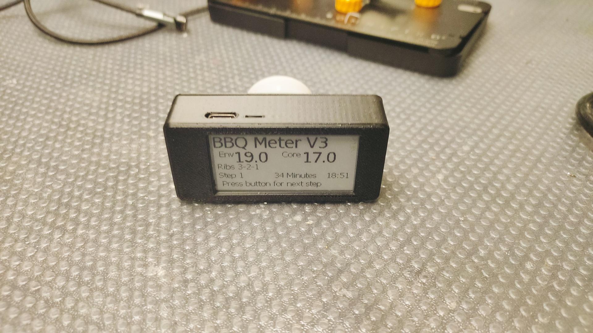
I worked on: RSS feed on a epaper display, Midi monitor and the MQTT Pong website.
RSS Feed display
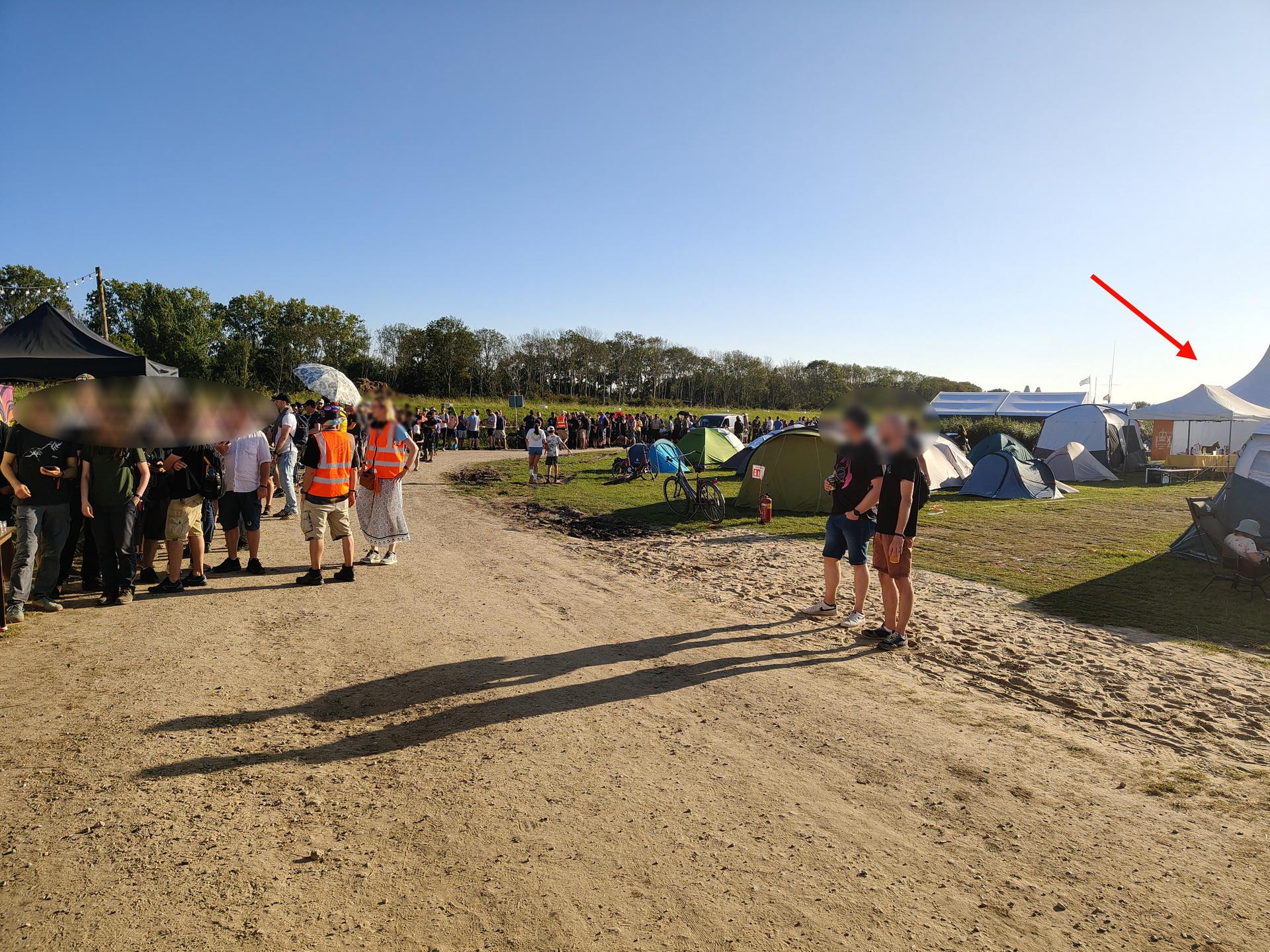
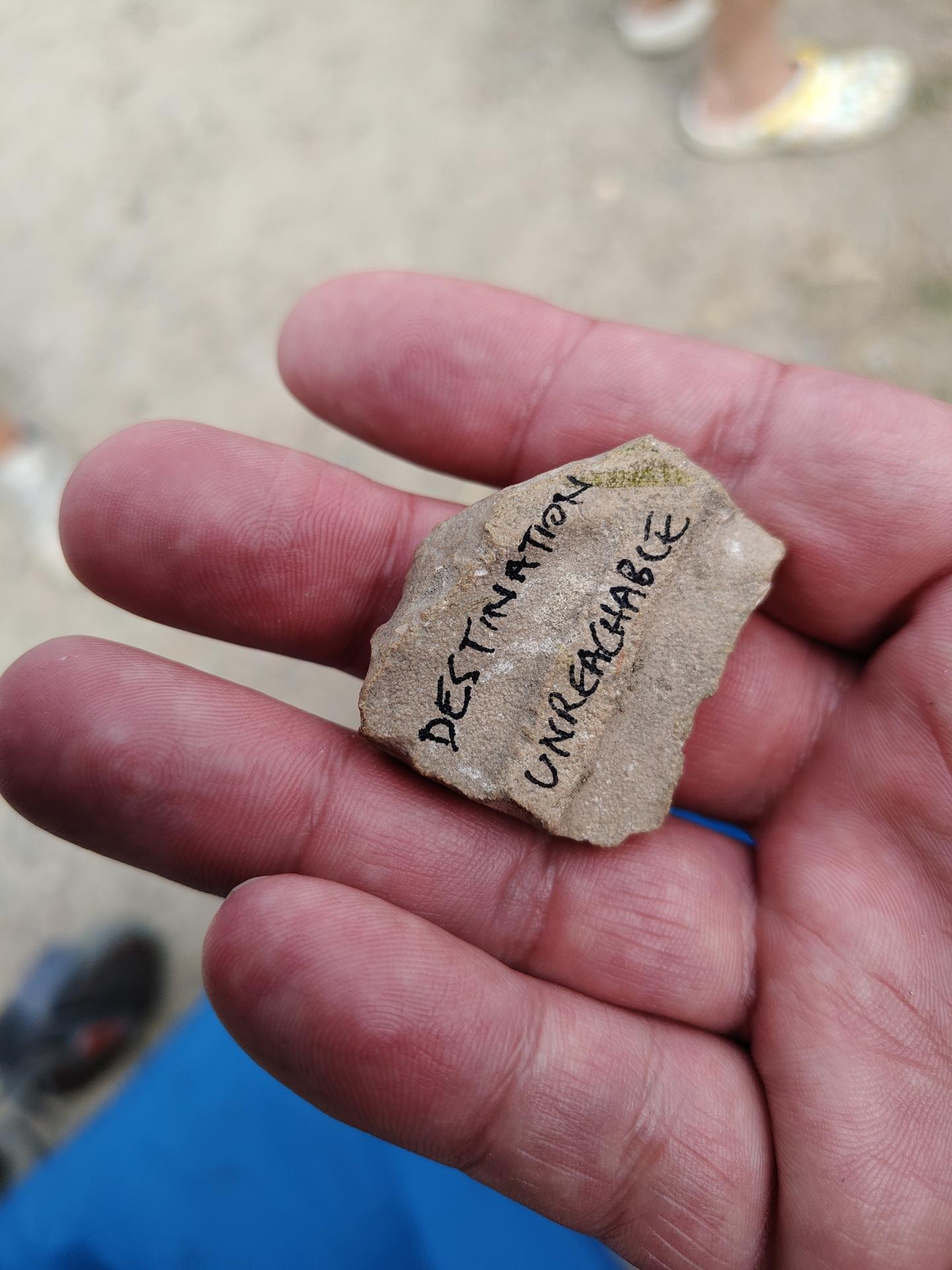
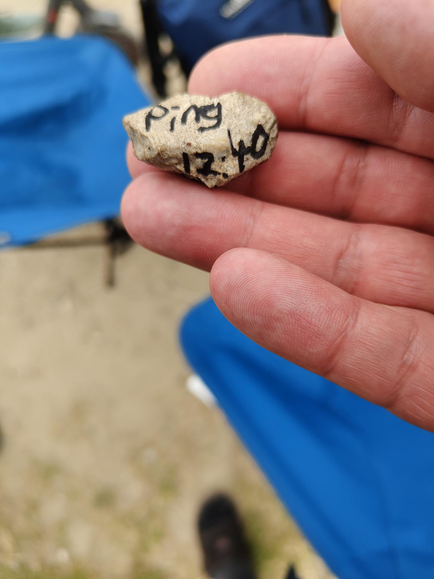
While waiting in line for the Badge:
A stone was passed from behind! It was a ping request. We passed it forward, and 15 minutes later a TTL time exceeded stone came from the front of the line. You gotta love those nerds!
Some other stones
The Badge: This should have got much potential .. Many misses, much to learn.
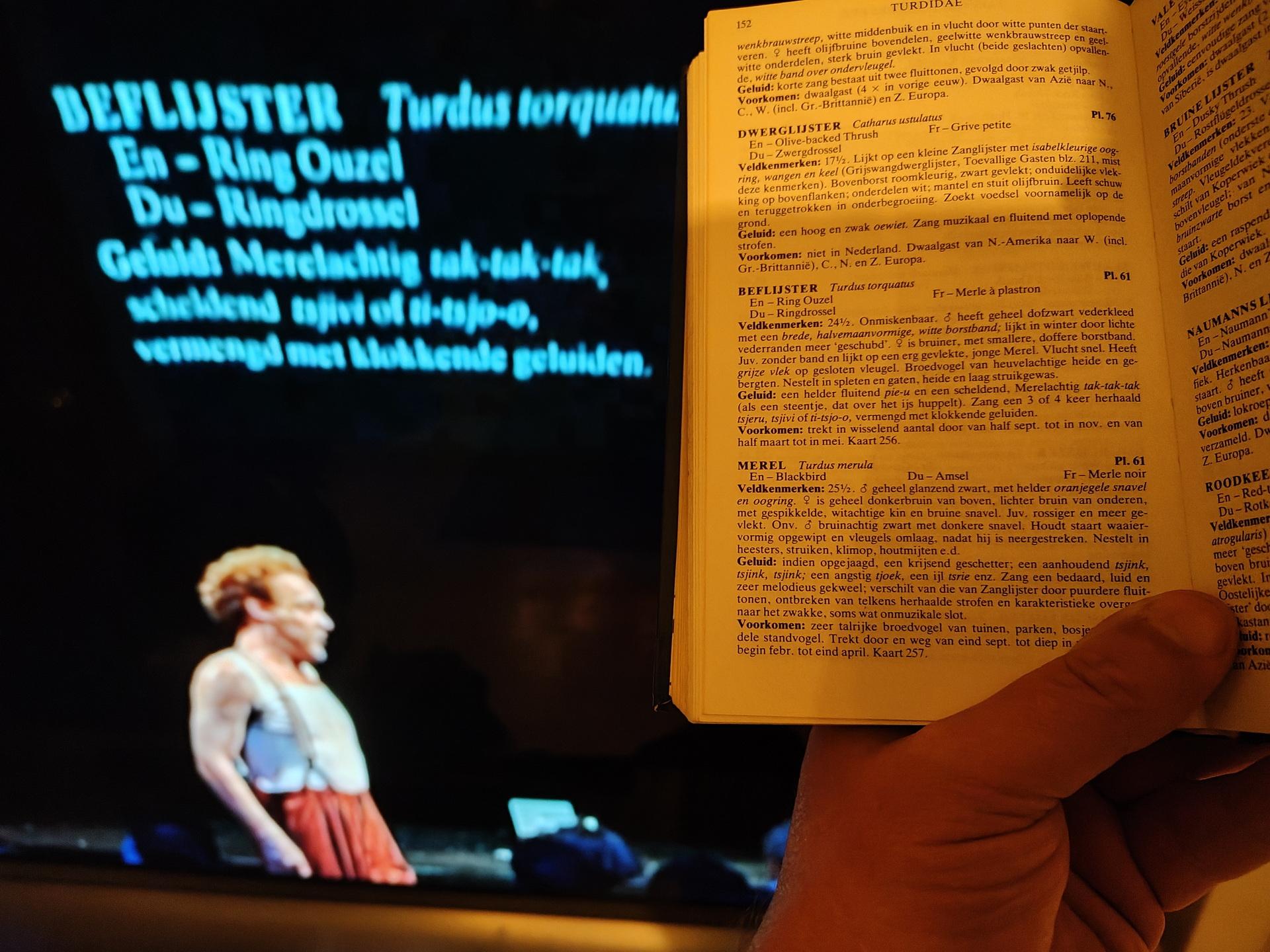
I bought Peterson’s Vogelgids, just for fun. It’s an old version, but that’s on purpose.
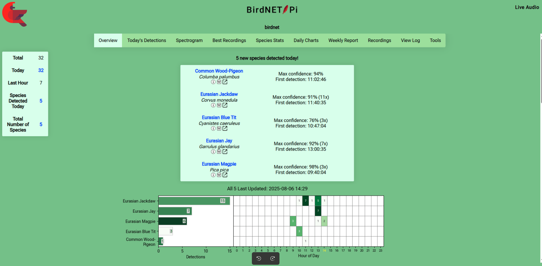
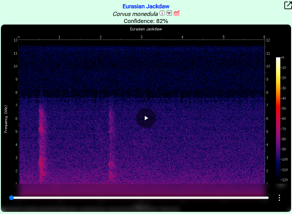
Then I saw a little project named BirdNet Pi. (I used the Android app already)
This is a Raspberry installation which recognises bird sounds. And gives you statistics about the detected birds. Cool for identifying birds in my garden.
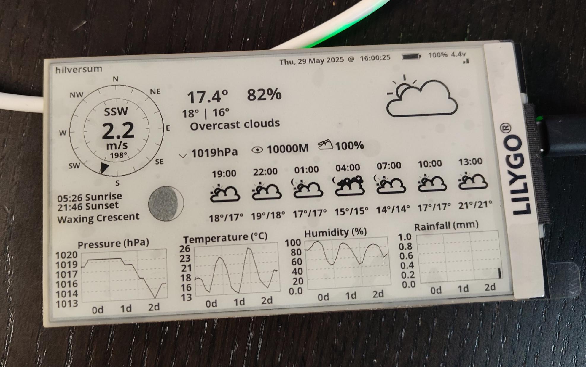
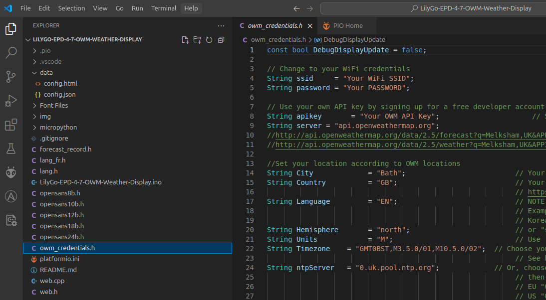
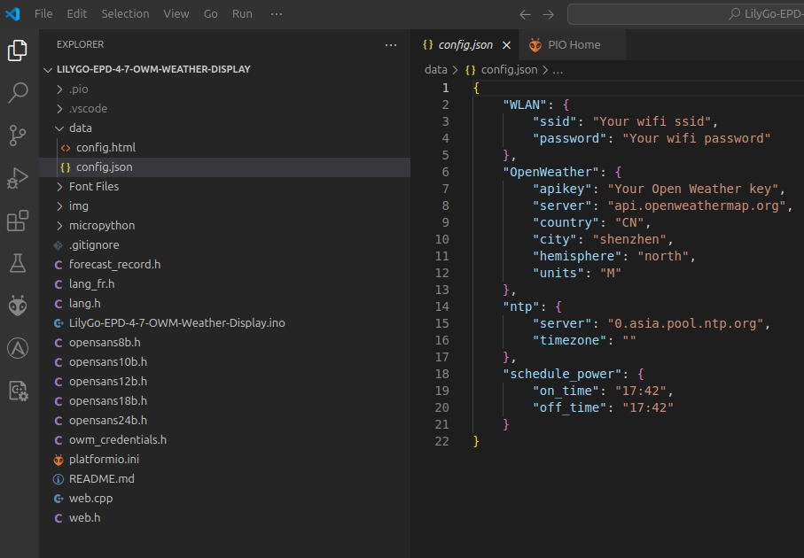
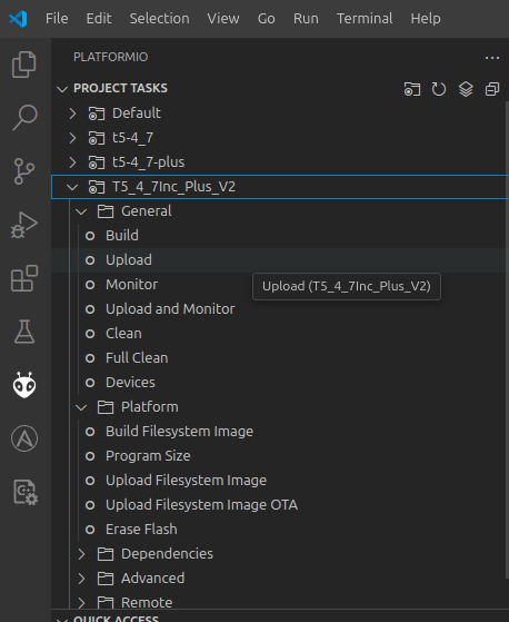
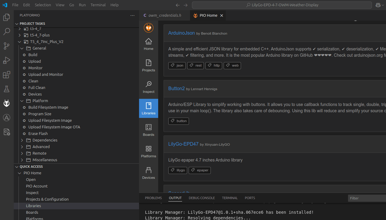
I was planning to make a RSS reader using this display, but I came across a weather display project I wanted to check out. (So I probably end up buying another one)
There are many questions and issues around this project using the S3.
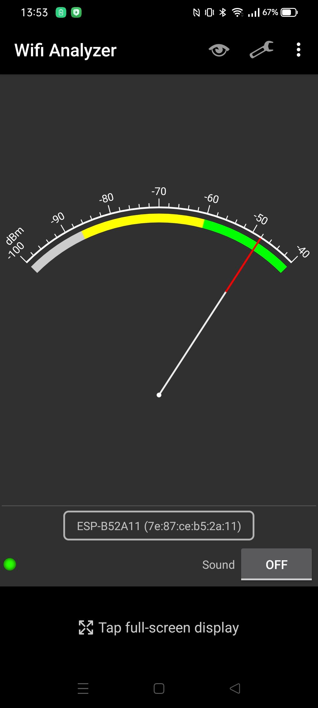
Its SSID started with ESP. So I probably am the one responsible for its existence. I’ve got a sh*tload of ESPs/NodeMCUs/8266 turned on 24-7.
Using a Wifi analizer I could narrow it down to my livingroom. Checked all devices, and they are all connected to my AccessPoint. (So no fallback AP mode)
The problem with this method is that you can’t figure out a direction.
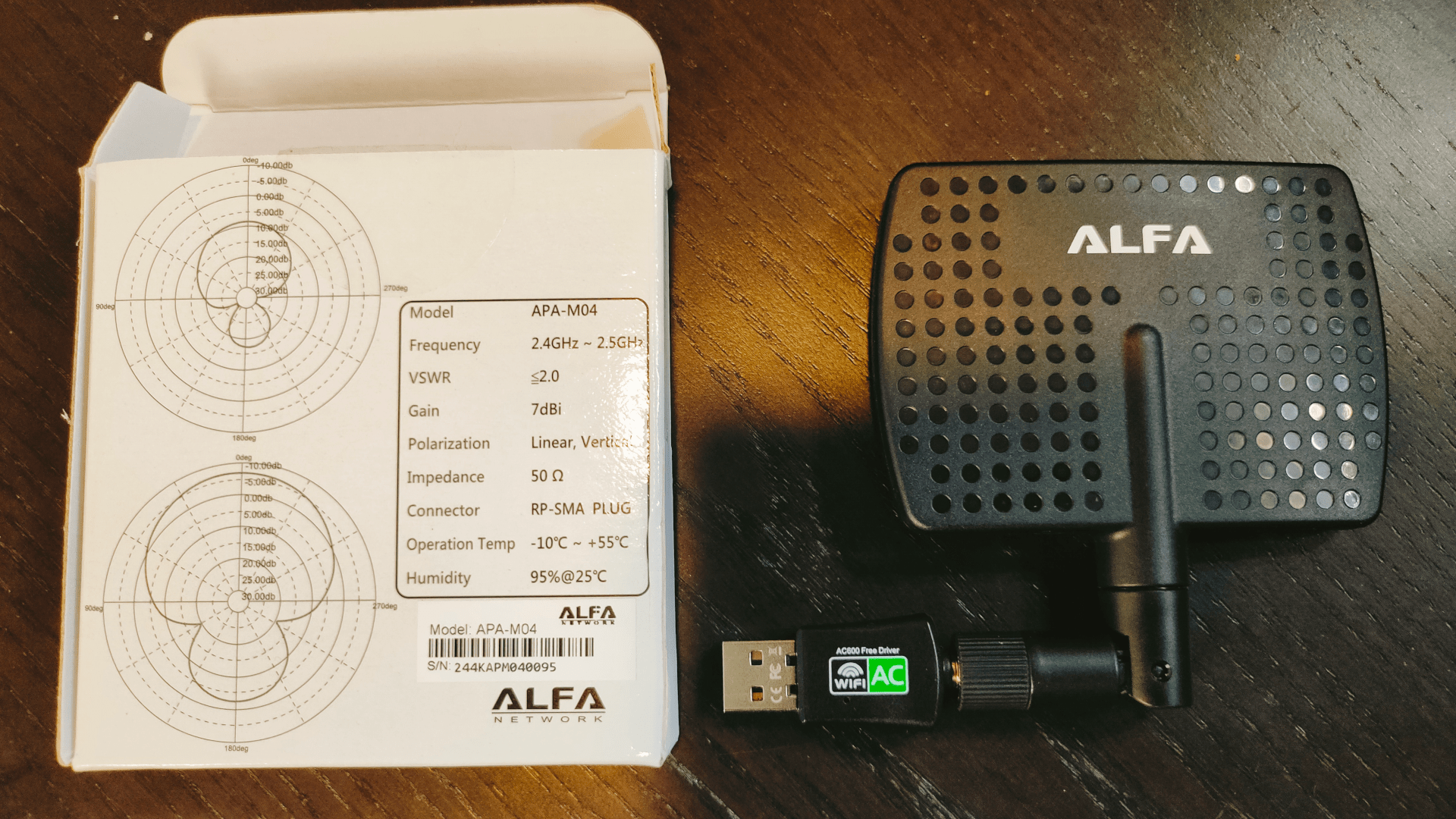
So I used this on my Laptop.
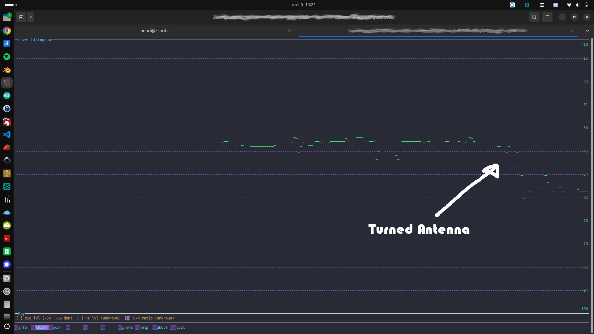
See graphs on the left
This is a directional antenna.
Using Wireshark and wavemon, I could find the direction.
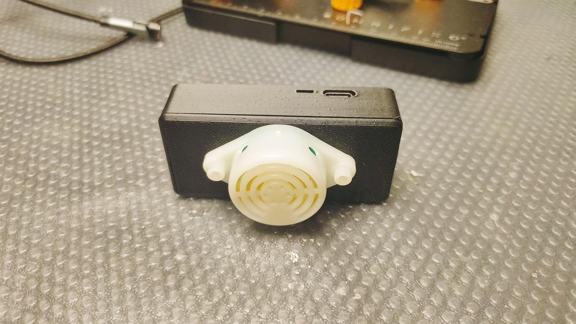
There were only two devices in the direction with the strongest signal. My photo viewer remote, and my mini turntable controller with RFID.
But these devices are working just fine! .. So lets disconnect the power. So it IS the mini recordplayer!
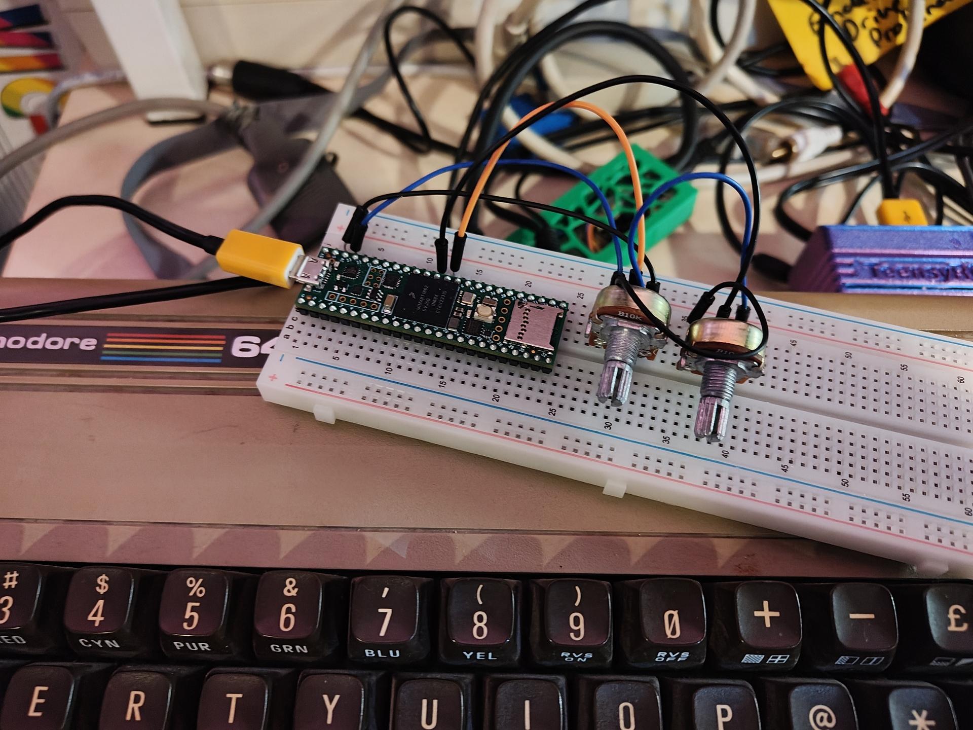
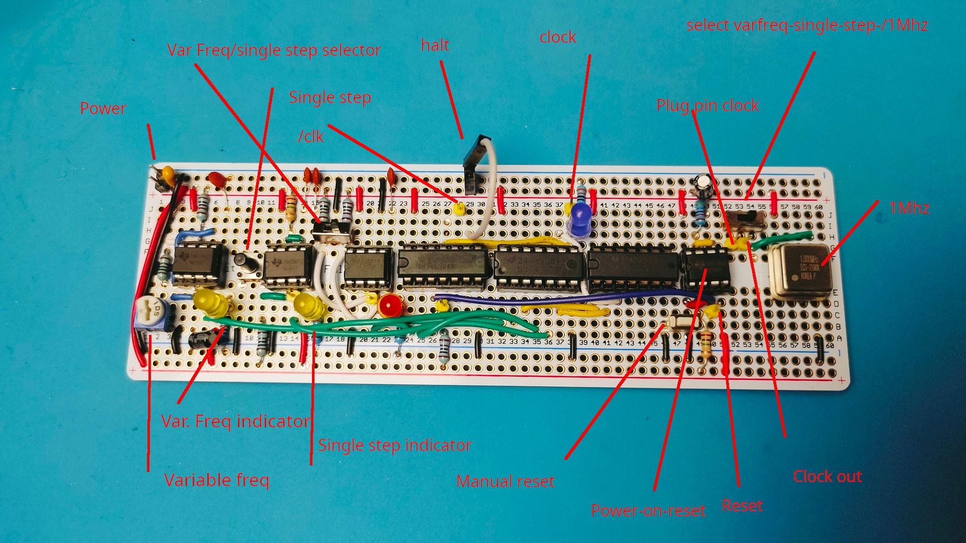
My previous build of the clock module is as Ben designed. Wellll . Not really, I added some components to change the clock range.
Okay, Ben’s design is awesome. Not because of its technical design. No, you will learn to use the NE555 chip in three ways! Variable freq, debounce with delay and a flip-flop like switch I added another function to it. While making my version. I added a 555 power-on reset pulse part.
I used a perm board (which is shorter than a regular breadboard) And I moved some components over and added some LEDs/pin headers. While doing so, I only used 3/4 of the board.
So I added a power-on reset part with a manual push-button. (Partly like the C64 power-on) I also added the 1Mhz crystal.
Rest of the boards will use JST connectors for the bus-connections.
I am working on big motor controllers and 3D print modelling for clients.
DISCLAIMER: Do this at own risk, I’m not responsible for loss of data!
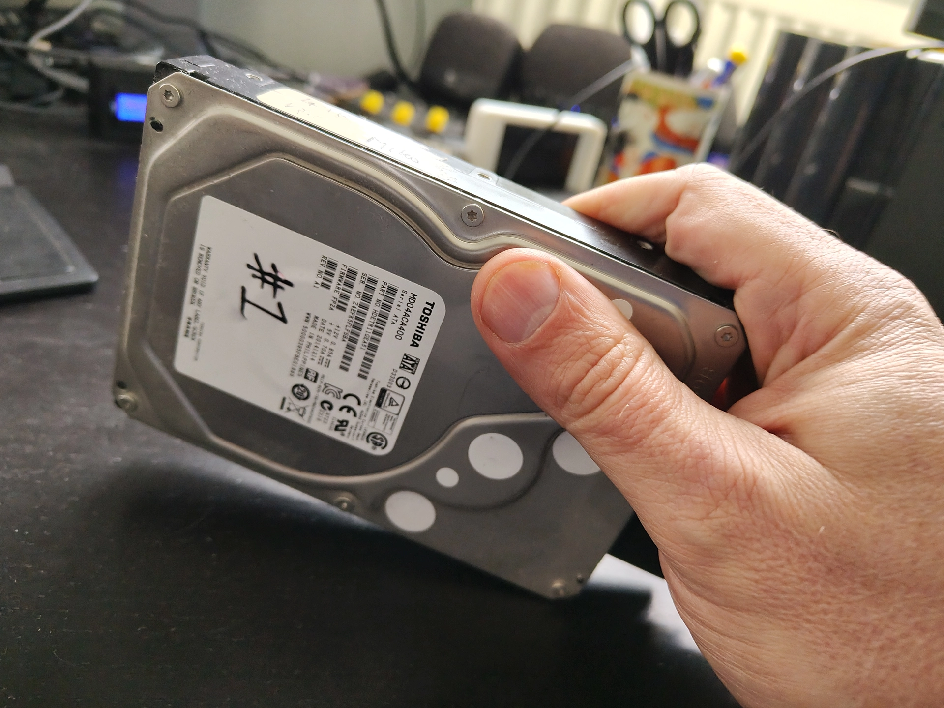
Today is the second time I fixed a dead hard disk.
A few years ago, I fixed one containing a university assignment. It took a while, but I managed to get it running long enough to make a backup of the data.
Today, a friend asked me to get the data from a drive containing family pictures.
Below the way I did this.
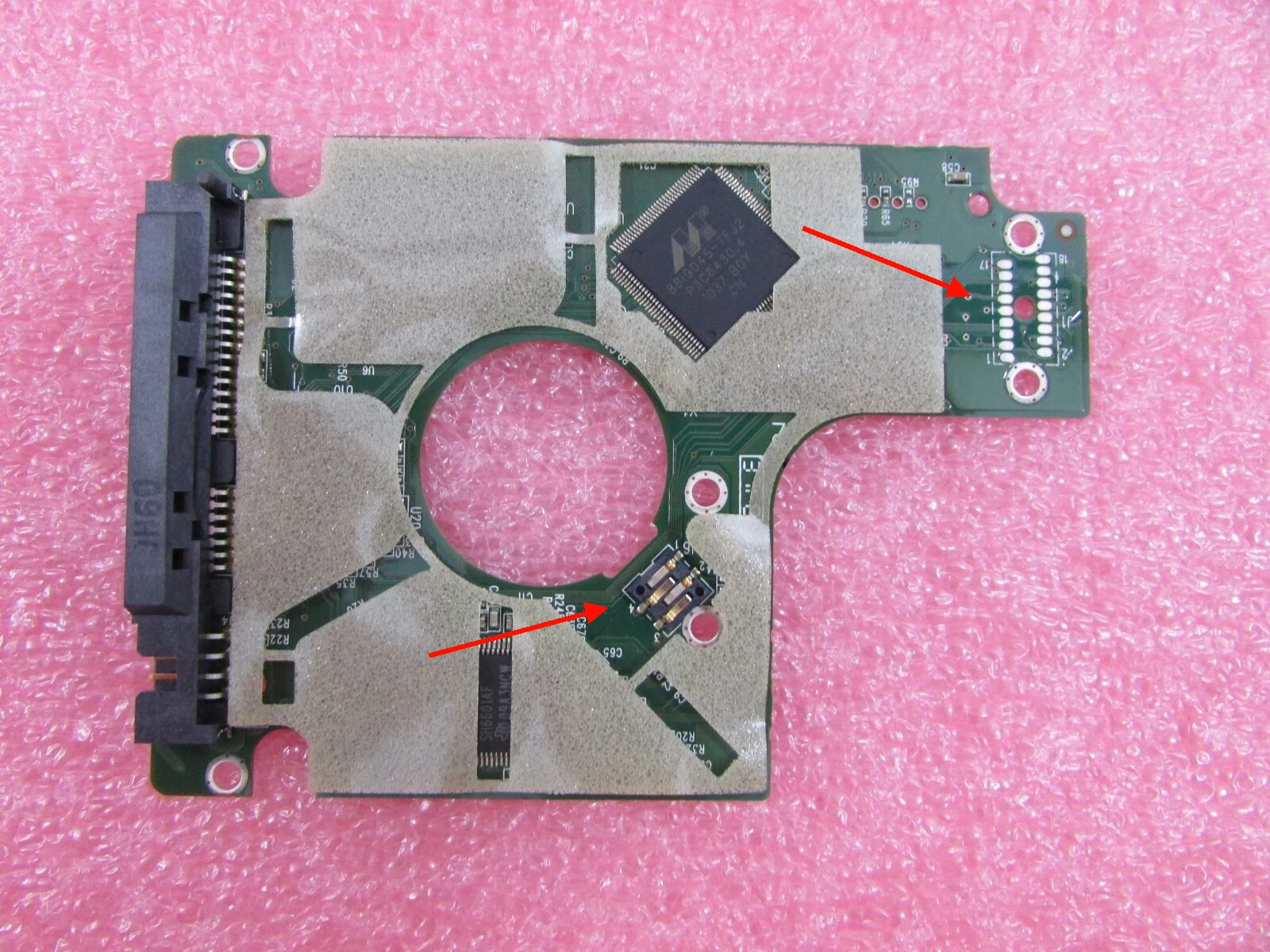
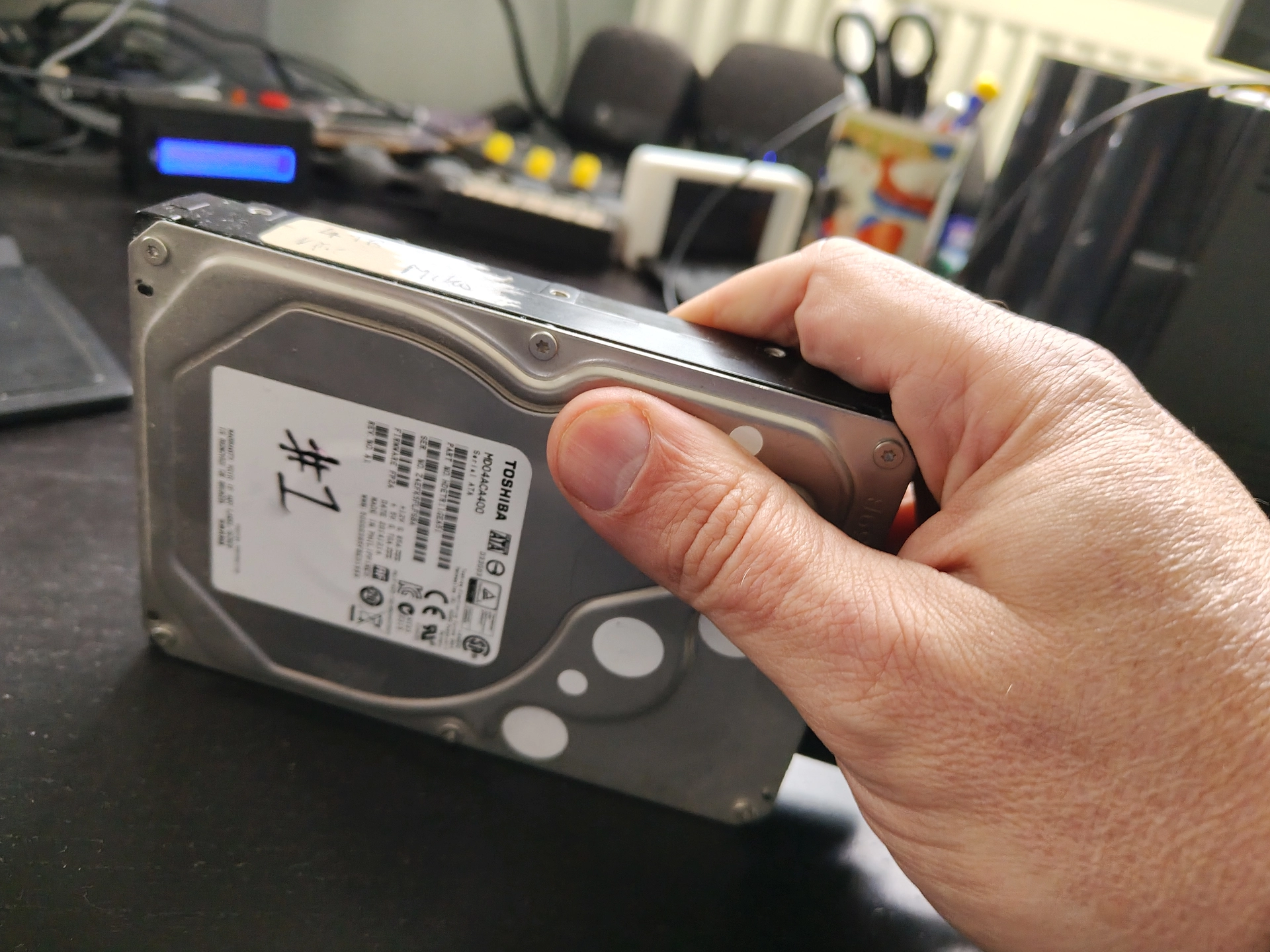
First thing to try: See if PCB has contact problems. Unscrew pcb and clean contacts with ISOPropanol. See red arrows.
If this fails, the head can be stuck. Do below, but be carefull.
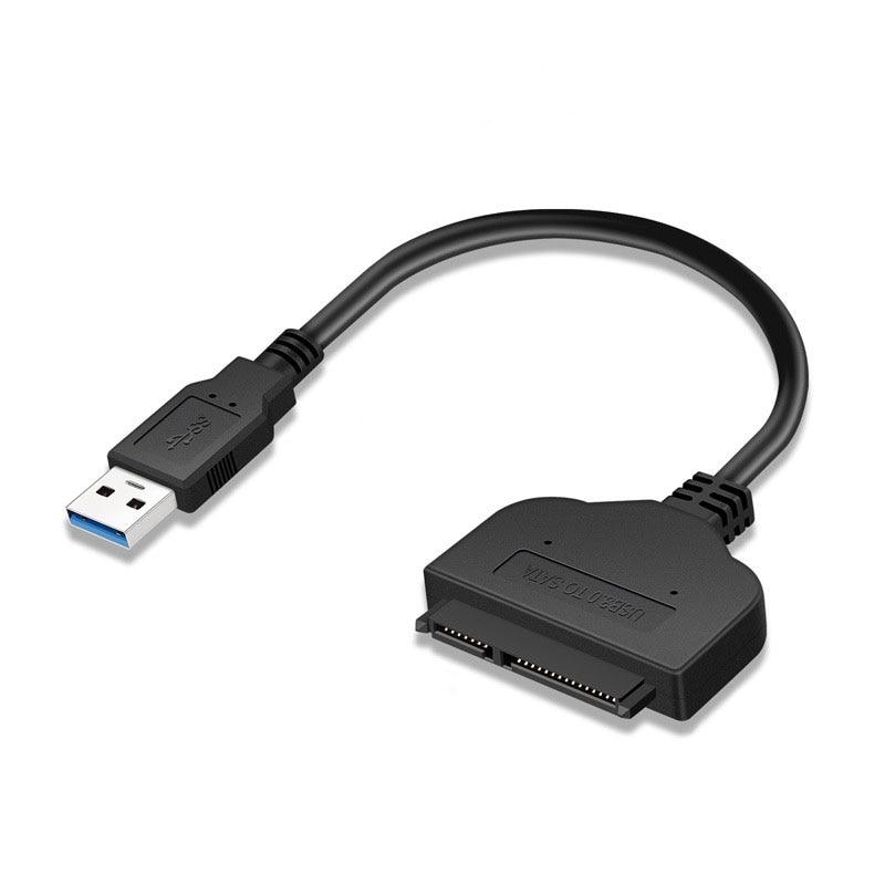
Use a Sata Adaptor so you can move the harddisk around.
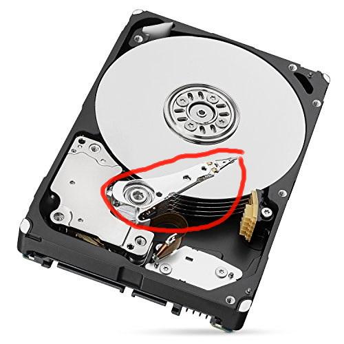
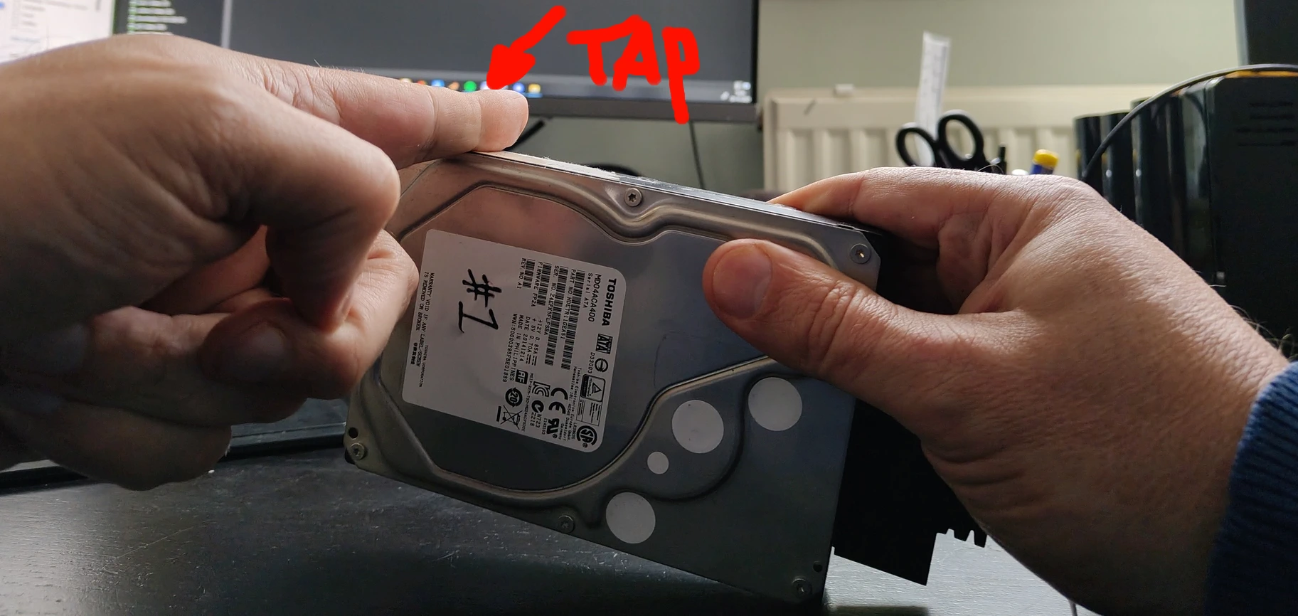
Try to figure out which way the actuator arm is pointing. (Thingy with the read sensor)
Do below while powered up. Point the hard disk with this arm upward. And let it fall vertically on the desk. (Perfectly vertical! Else you may risk head clashing against platters)
When you have a smaller hard disk you can tap the side.
In both cases I managed to get most data from these drives!
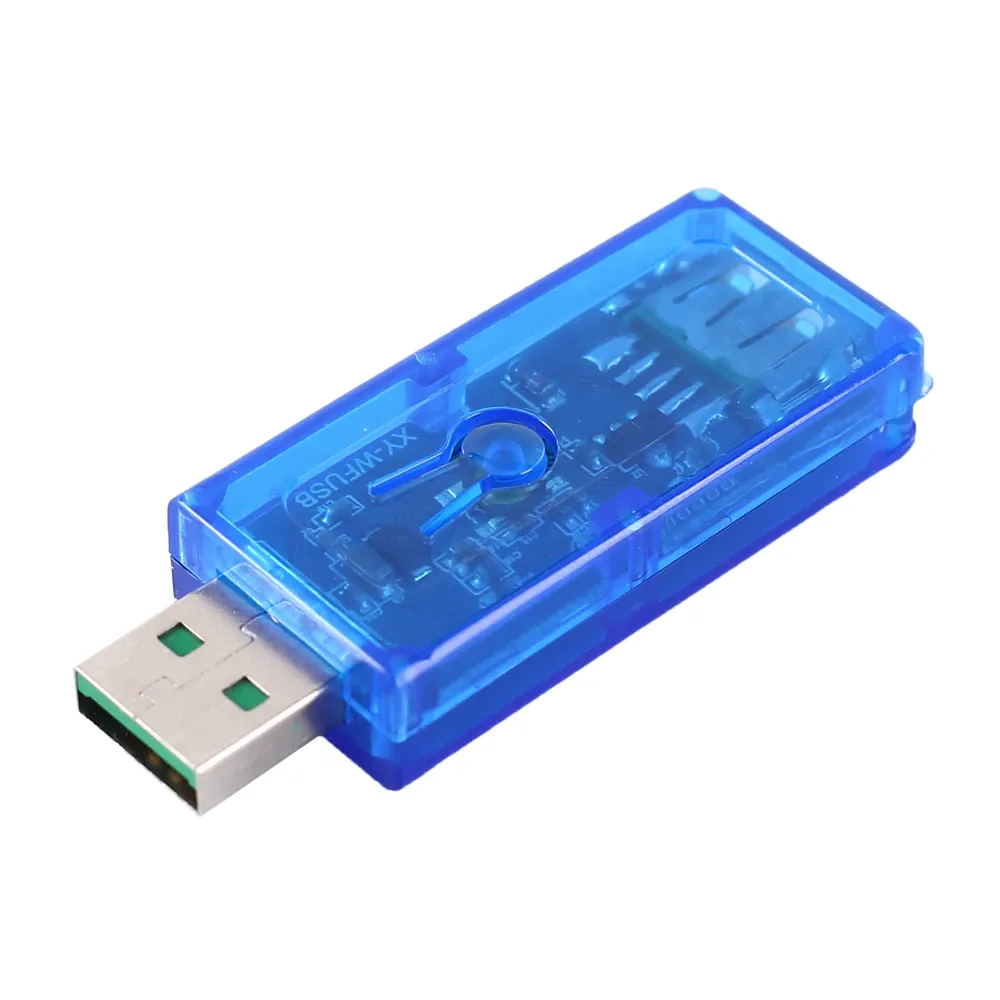
substitutions:
  name: usb-relay
  friendly_name: "USB Relay"
  default_state: "RESTORE_DEFAULT_OFF"


esphome:
  name: xyusb1
  friendly_name: xyusb1

esp8266:
  board: esp01_1m

# Enable logging
logger:

# Enable Home Assistant API
api:
  encryption:
    key: "ndm8xxxxxxxxxxxxxxxxxjlvrggJv3a1BkY="

ota:
  - platform: esphome
    password: "12cc9xxxxxxxxxxxxxxxxfb6a01e672"

wifi:
  ssid: !secret wifi_ssid
  password: !secret wifi_password

  # Enable fallback hotspot (captive portal) in case wifi connection fails
  ap:
    ssid: "Xyusb1 Fallback Hotspot"
    password: "xxxxxxxxxxx"

captive_portal:

time:
  - platform: homeassistant

# Blue LED
status_led:
  pin:
    number: GPIO16

# Relay
switch:
  - platform: gpio
    id: switch_relay
    pin: GPIO5

  # Green LED
  - platform: gpio
    pin: GPIO14
    id: green_led
    inverted: true # start on

  # Switch template to link relay and green LED states
  # LED is on when relay is off
  - platform: template
    id: relay
    name: "${friendly_name}"
    lambda: |-
      if (id(switch_relay).state) {
        return true;
      } else {
        return false;
      }
    turn_on_action:
        - switch.turn_on:
            id: green_led
        - switch.turn_on:
            id: switch_relay
    turn_off_action:
        - switch.turn_off:
            id: green_led
        - switch.turn_off:
            id: switch_relay

# Button
binary_sensor:
  - platform: gpio
    id: hardware_button
    pin:
      number: GPIO04
      mode: INPUT_PULLUP
      inverted: True
    on_press:
      - switch.toggle: relay

# WiFi Signal Sensor
sensor:
  - platform: wifi_signal
    name: "WiFi Status"
    update_interval: 60s

# Restart button
button:
  - platform: restart
    name: "Restart"
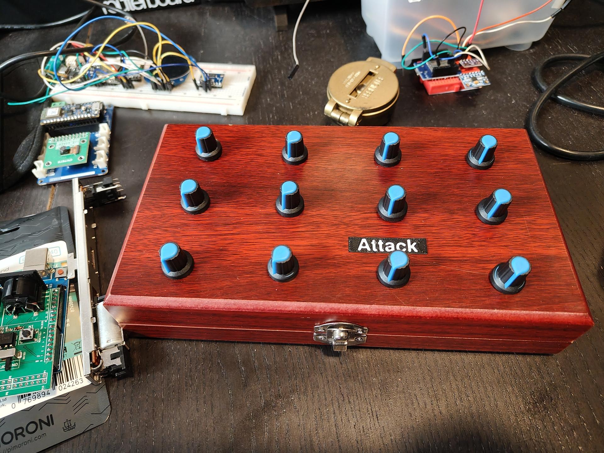
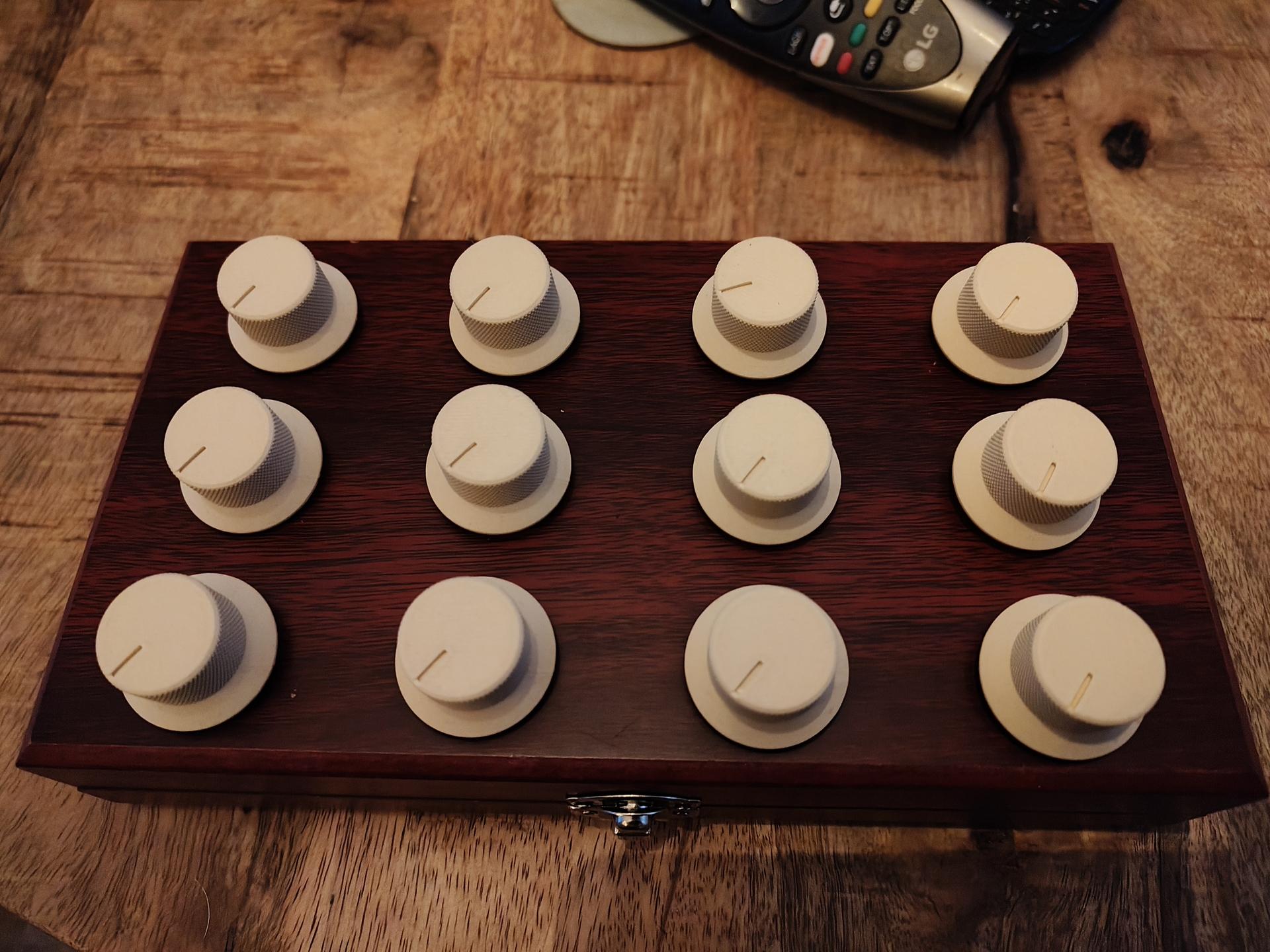
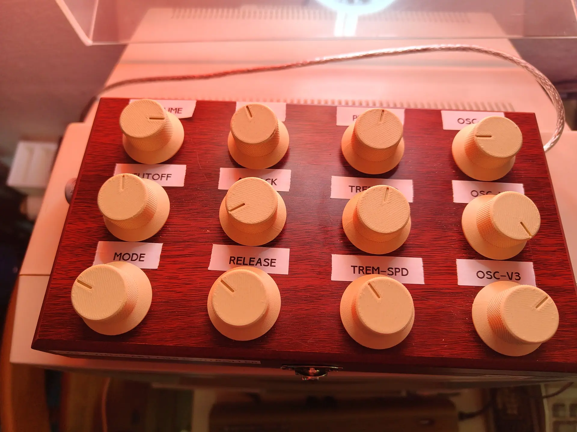
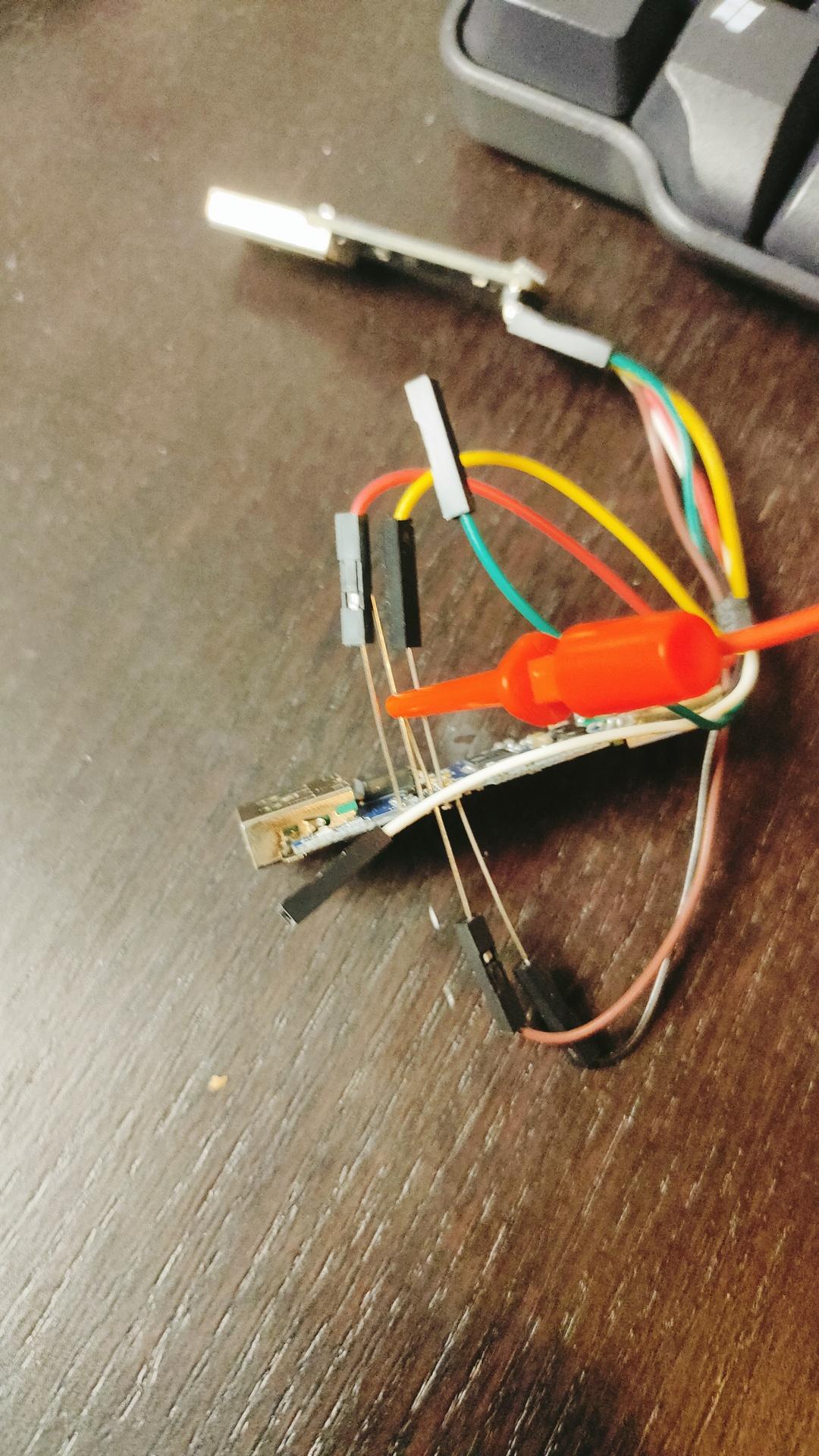
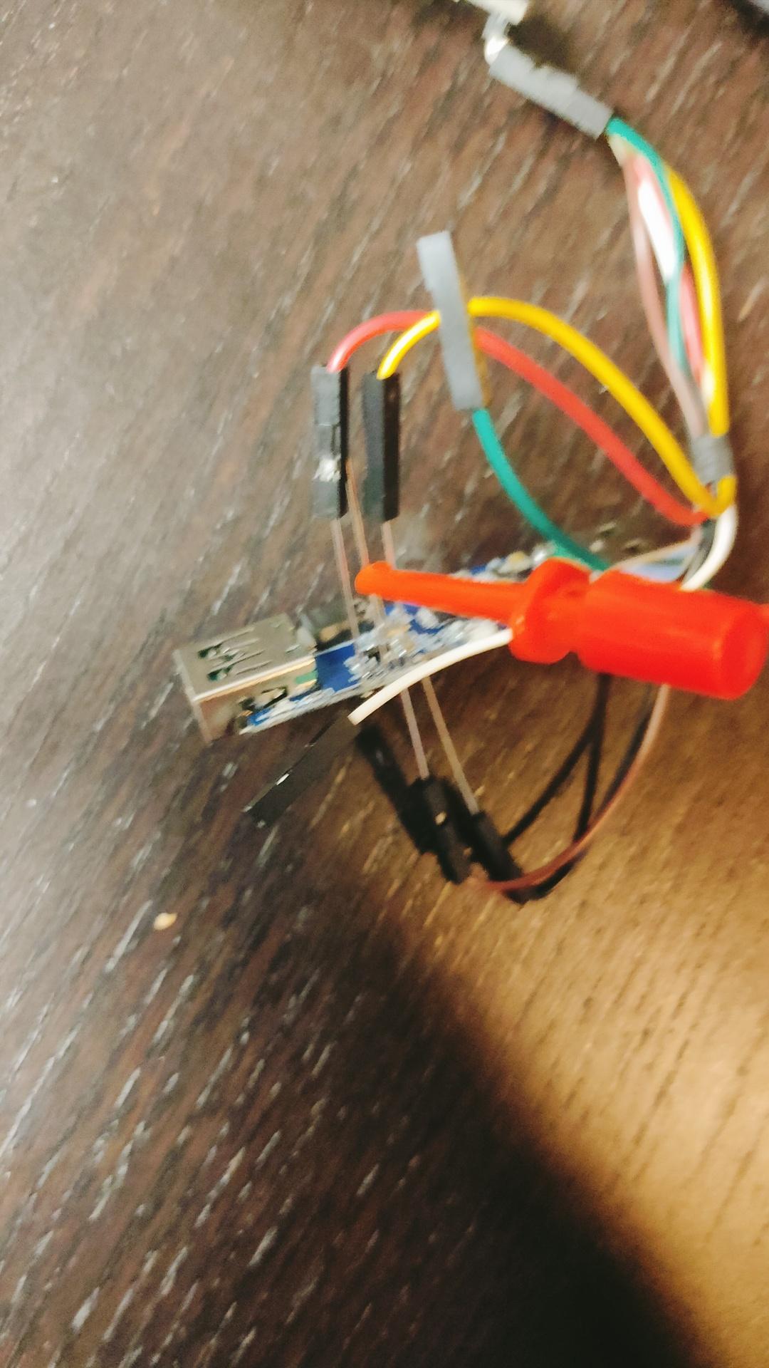
Reflashed my USB Volume button and added a LED-Ring.
Example is green and blue.
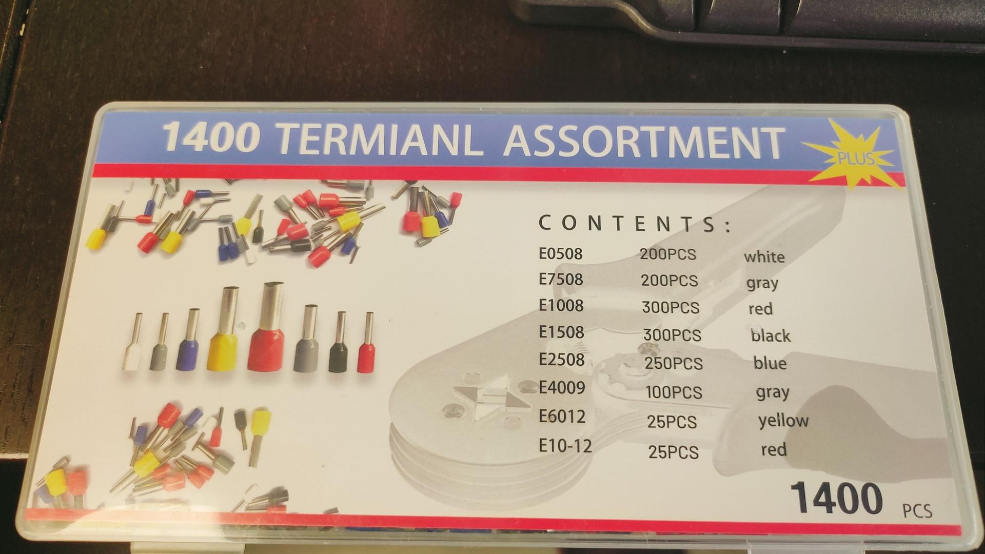
Funny text on box
What is a termianl assortment? LOL
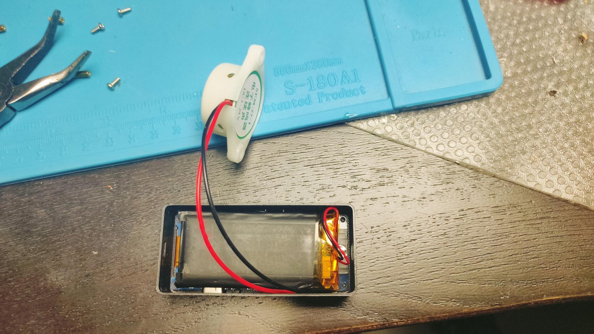
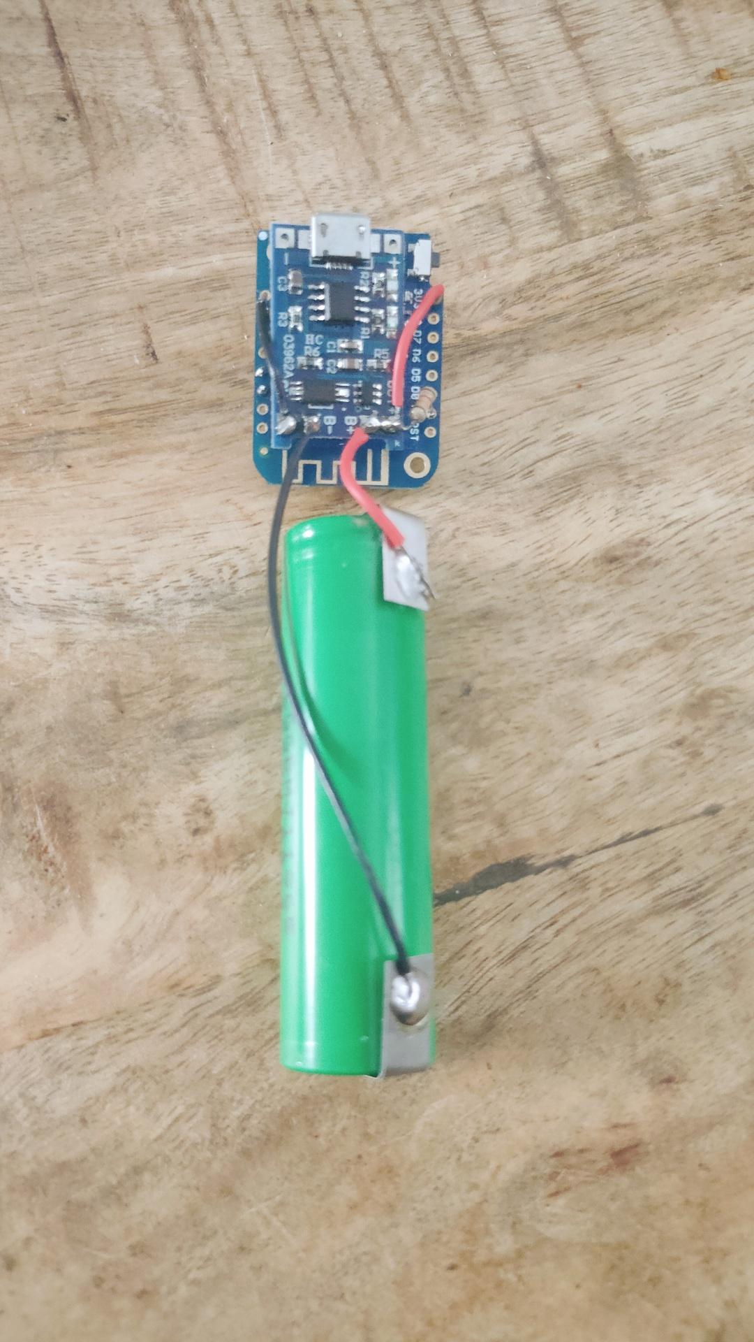
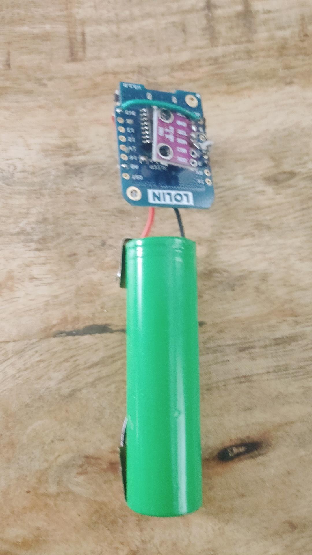
Wireless Temperature/Humidity sensor for ESPHome.
Wemos D1 mini with deep sleep, voltage monitoring using A0 line. BME280 Temperature/Humidity sensor. And a 18650 battery with TP4065 battery manager. Now 3D print a little case.