In the past, I’ve played with a standard lidar device.
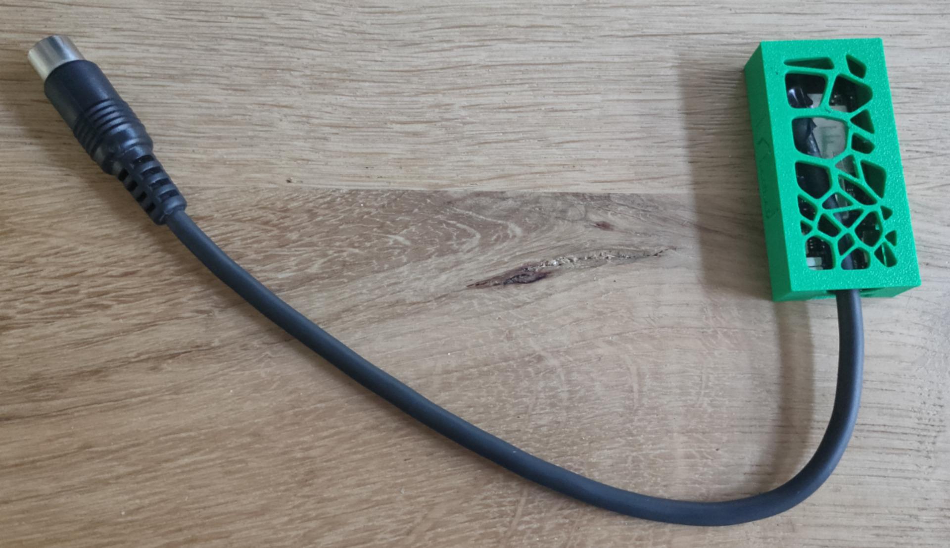
Now it is time to check out a 360 version.
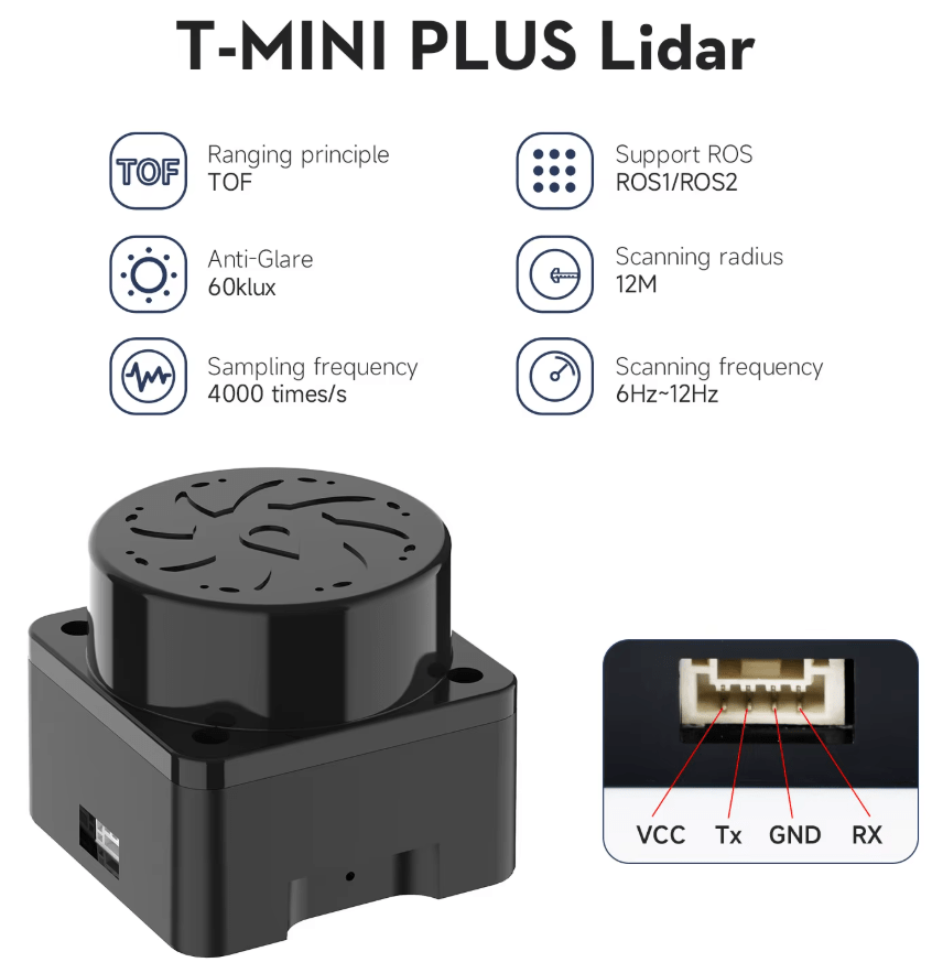
This one is very small (40mm x 40mm x 35mm)
Provided examples didn’t work. (People with same error on the Github issues tracker page had the same)
I changed the python script so it worked also with this YDLidar T-mini Plus version.
Next to-do, put this on my robot car.
Code:
import os
import ydlidar
import time
import sys
from matplotlib.patches import Arc
import matplotlib.pyplot as plt
import matplotlib.animation as animation
import numpy as np

RMAX = 32.0

fig = plt.figure()
lidar_polar = plt.subplot(polar=True)
lidar_polar.autoscale_view(True,True,True)
lidar_polar.set_rmax(RMAX)
lidar_polar.grid(True)
ports = ydlidar.lidarPortList();
port = "/dev/ttyUSB0";
for key, value in ports.items():
    port = value;

laser = ydlidar.CYdLidar();

laser.setlidaropt(ydlidar.LidarPropSerialPort, port);
laser.setlidaropt(ydlidar.LidarPropSerialBaudrate, 230400);
laser.setlidaropt(ydlidar.LidarPropLidarType, ydlidar.TYPE_TRIANGLE);
laser.setlidaropt(ydlidar.LidarPropDeviceType, ydlidar.YDLIDAR_TYPE_SERIAL);
laser.setlidaropt(ydlidar.LidarPropScanFrequency, 10.0);
laser.setlidaropt(ydlidar.LidarPropSampleRate, 4);
laser.setlidaropt(ydlidar.LidarPropSingleChannel, False);
laser.setlidaropt(ydlidar.LidarPropMaxAngle, 180.0);
laser.setlidaropt(ydlidar.LidarPropMinAngle, -180.0);
laser.setlidaropt(ydlidar.LidarPropMaxRange, 16.0);
laser.setlidaropt(ydlidar.LidarPropMinRange, 0.02);
laser.setlidaropt(ydlidar.LidarPropIntenstiy, True);

scan = ydlidar.LaserScan()

def animate(num):

    r = laser.doProcessSimple(scan);
    if r:
        angle = []
        ran = []
        intensity = []
        for point in scan.points:
            angle.append(point.angle);
            ran.append(point.range);
            intensity.append(point.intensity);
        lidar_polar.clear()
        lidar_polar.scatter(angle, ran, c=intensity, cmap='hsv', alpha=0.95, marker=".")

ret = laser.initialize();
if ret:
    ret = laser.turnOn();
    if ret:
        ani = animation.FuncAnimation(fig, animate, interval=50)
        plt.show()
    laser.turnOff();
laser.disconnecting();
plt.close();