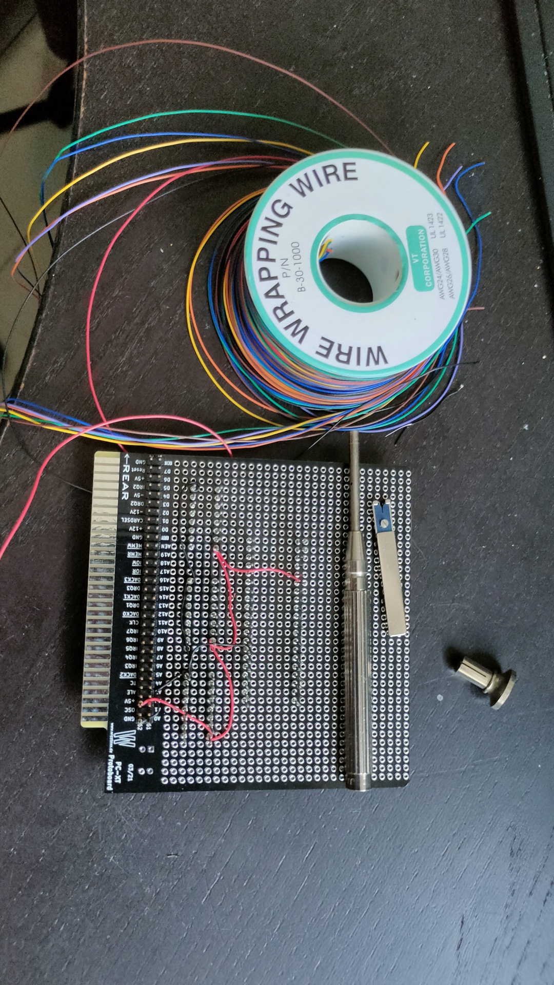
Today I got this card (I bought it on Ebay)
It’s fitted with a 64Mb card. Note: the XT at my parents place had a 20Mb harddisk!
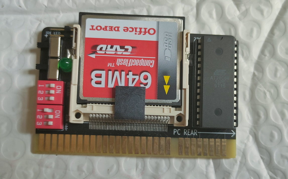
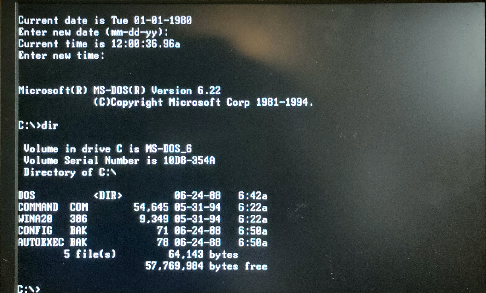
It can boot / emulate a harddisk with MsDos installed.
Replace an old or dead hard drive in a vintage PC with a hassle-free, reliable CompactFlash card!
Plug-in and go! (well, as much as you can expect with these old machines)Brand new!
Built and tested.Open Source!
This bootable expansion card provides a Compact Flash card interface to 8-bit ISA systems such as PC/XT. Typically paired with a 64MB or 1GB CF card. Silent, and more reliable than an old mechanical hard drive.
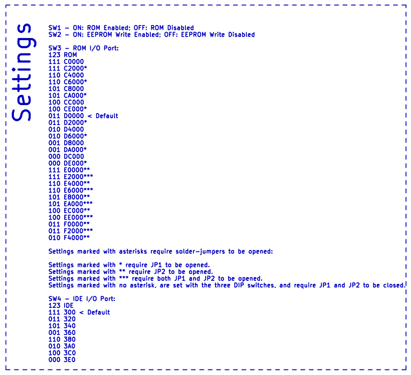
By default the XT-IDE BIOS comes configured for:
XT(and higher)-compatible BIOS.
Use the XT-CF-Mini’s IDE interface at 300h, no IRQ.
Boot first hard drive unless user presses A for floppy.
Any of the above can be changed with the simple DOS utility and built-in switches.Switches and jumpers control:
I/O port for the 8-bit IDE (CF) interface
I/O port for the Option ROM
Option ROM Enable
Option ROM Write-protectNote: Not all CF cards will work. Most work, but some don’t adhere to the CF standard fully, and won’t work. The full size XT-IDE card with an IDE>CF adapter, is compatible with more CF cards.
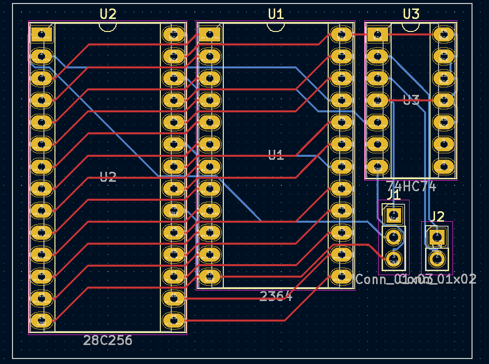
https://github.com/Bluelavasystems/XT-IDE-CF-MINI
XT-CF-Mini Pcb designed by Monotech Pc’s and released opensource GNU General Public License v3.0
It is from Blue Lava Systems, who took the schematics from Sergey Kiselev, who took the design from James Pearce.
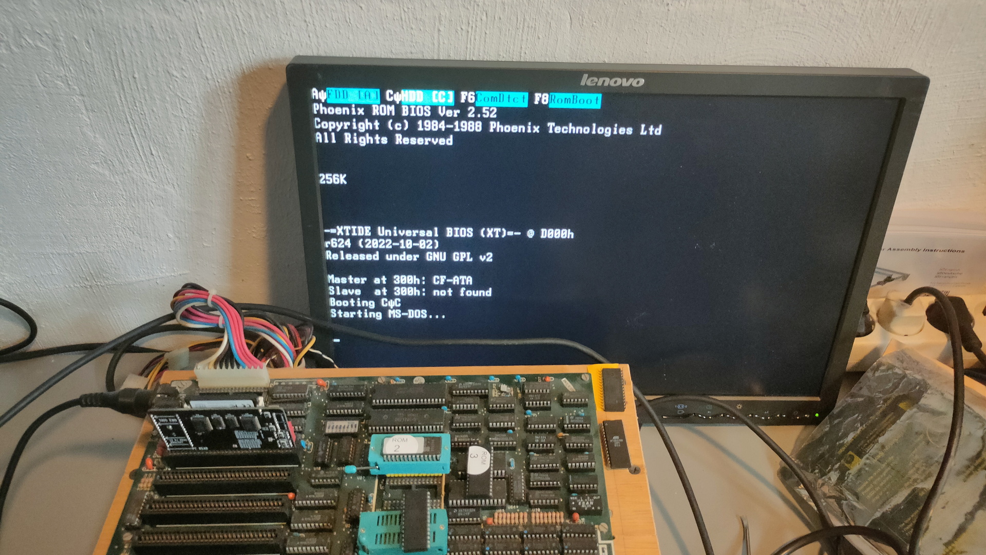
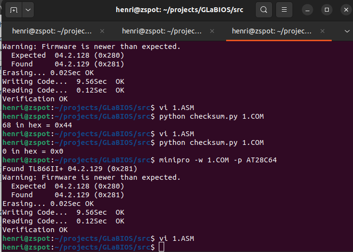
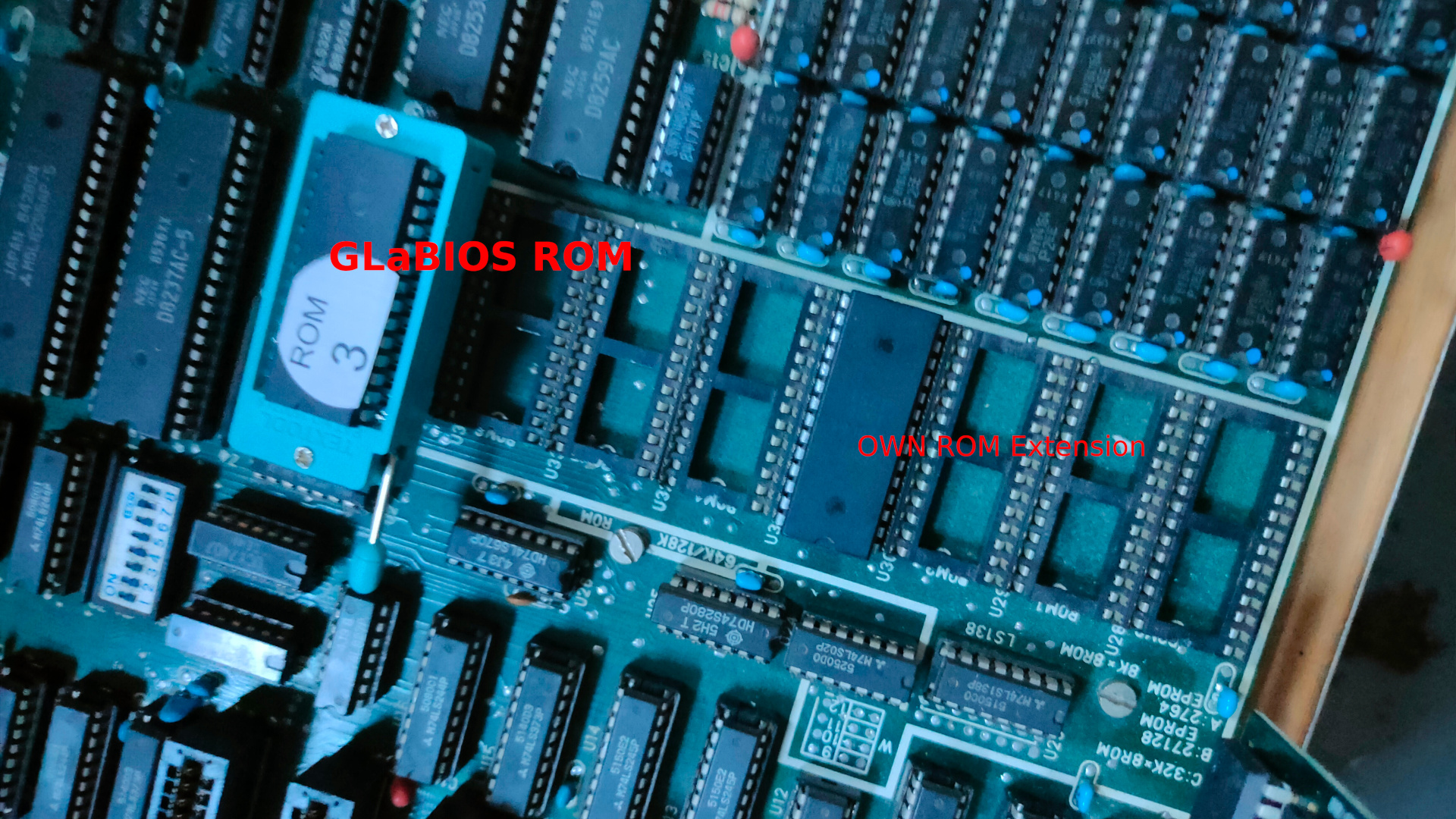
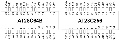
The harddisk extension is XT-IDE Universal BIOS.
And can be flashed.
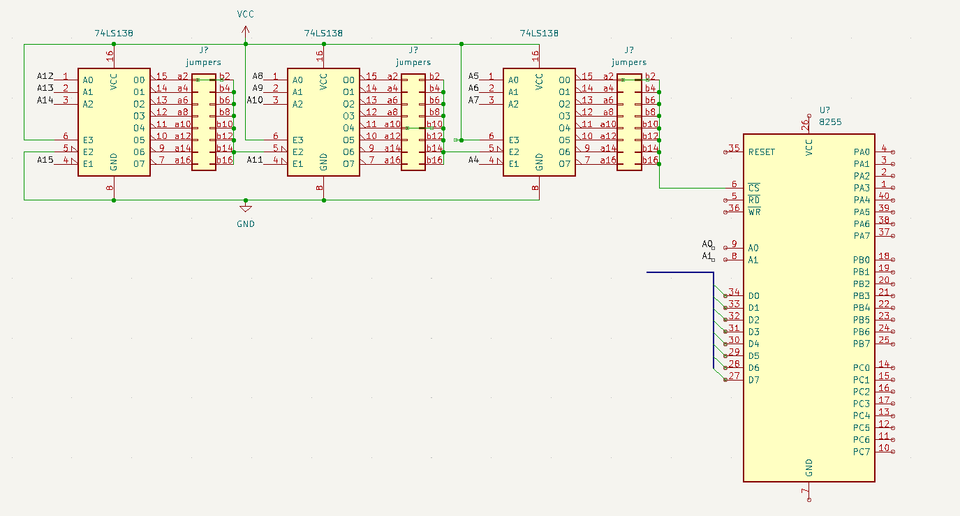
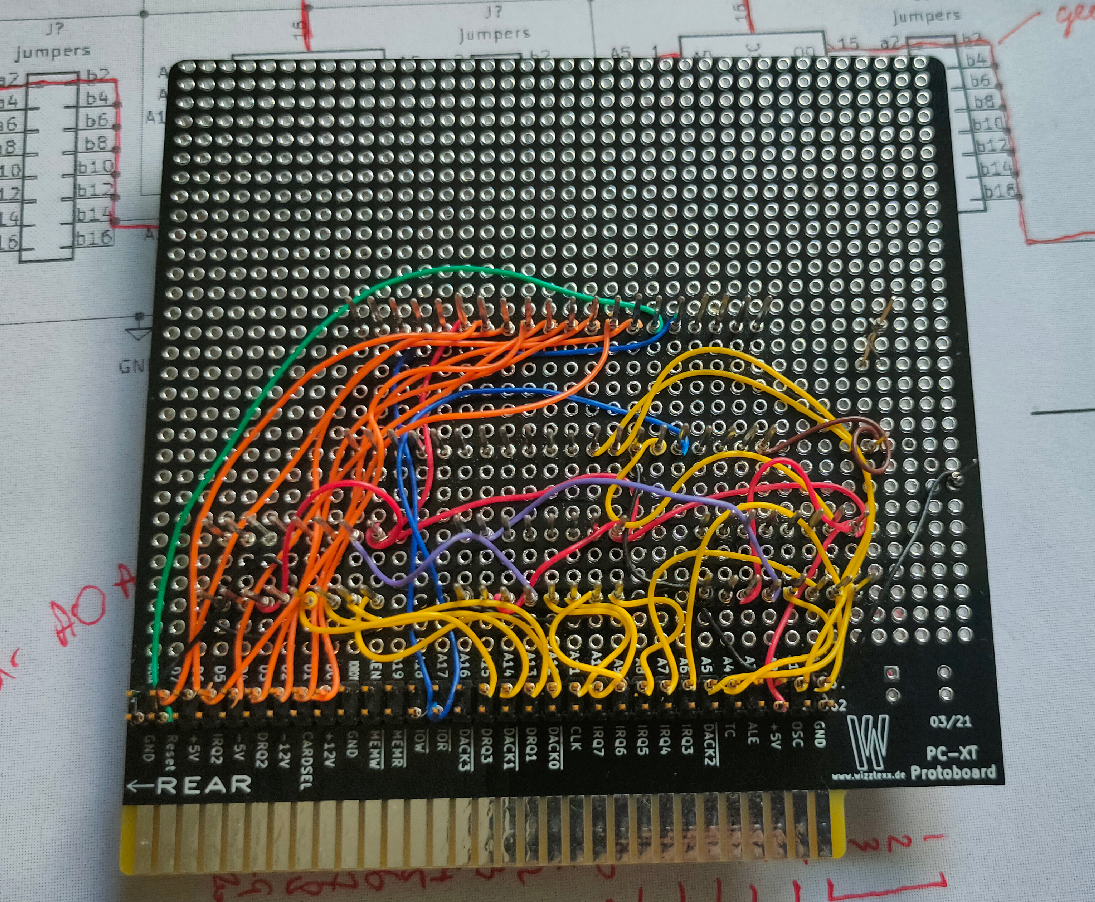
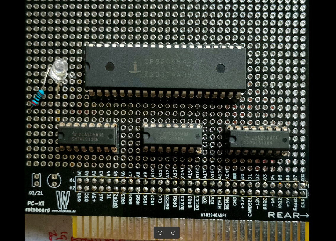
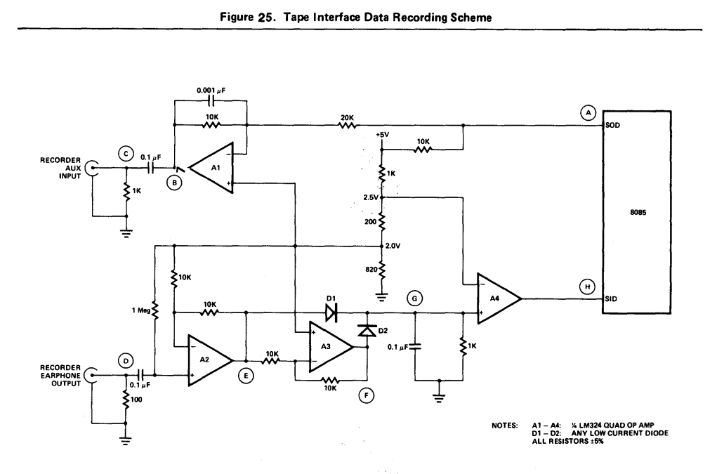
Schematic below
ROM address D0000, and IO port 300h does not need a IRQ
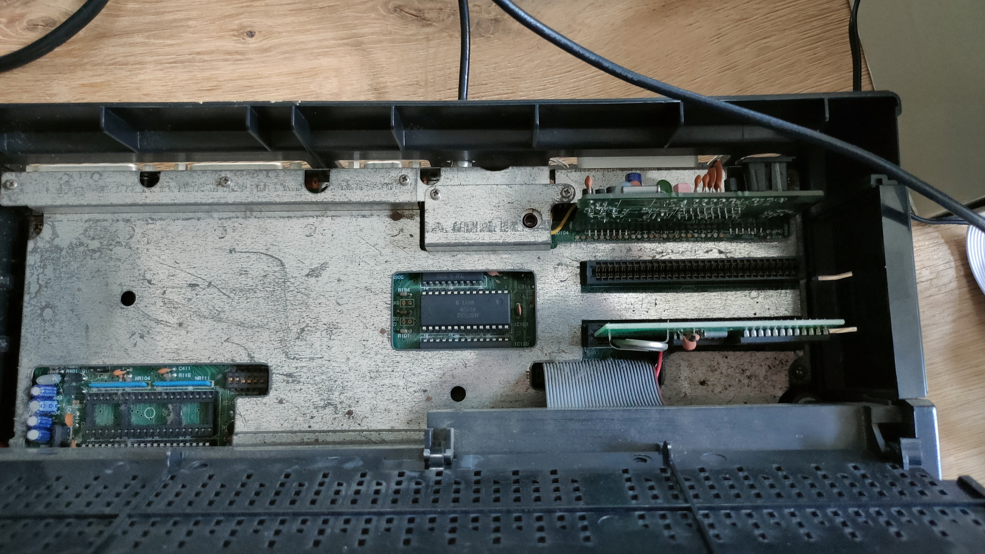
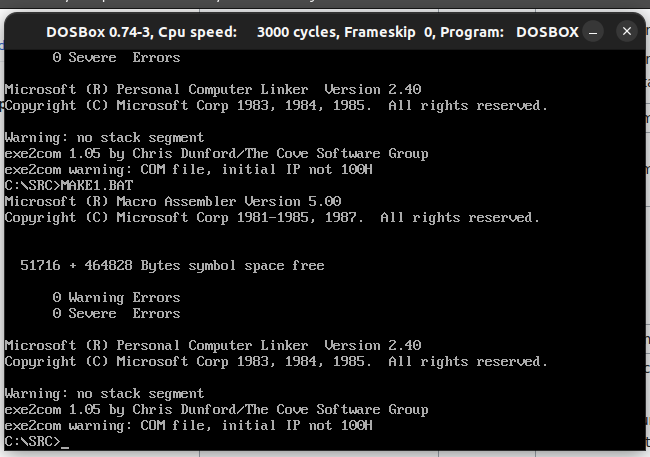
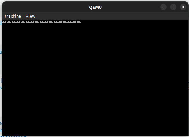
After installing this on my 8088/v20 motherboard I tested this with GlaBIOS, but it gave me one beep, and after that it woukd reset the machine.
Testing with the original Phoenix Bios and PCXtBios worked for me.
UPDATE: Bad contacts and a eeprom I didn’t trust.
Greg gave me version 0.2.5 of Glabios, which I burned to a new eeprom. And I cleaned some contacts.
(Checksum rom changed with every reset)
The Card and my extension bios both run with all bios-ses