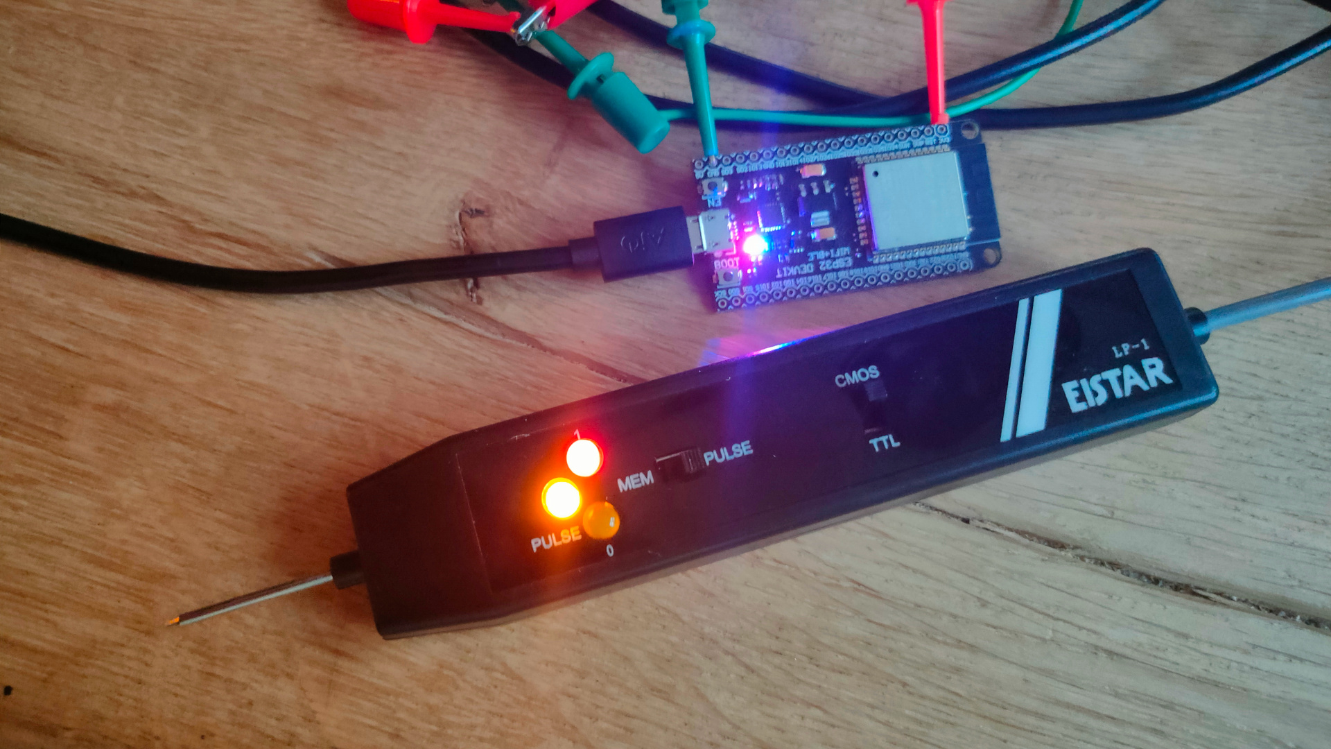
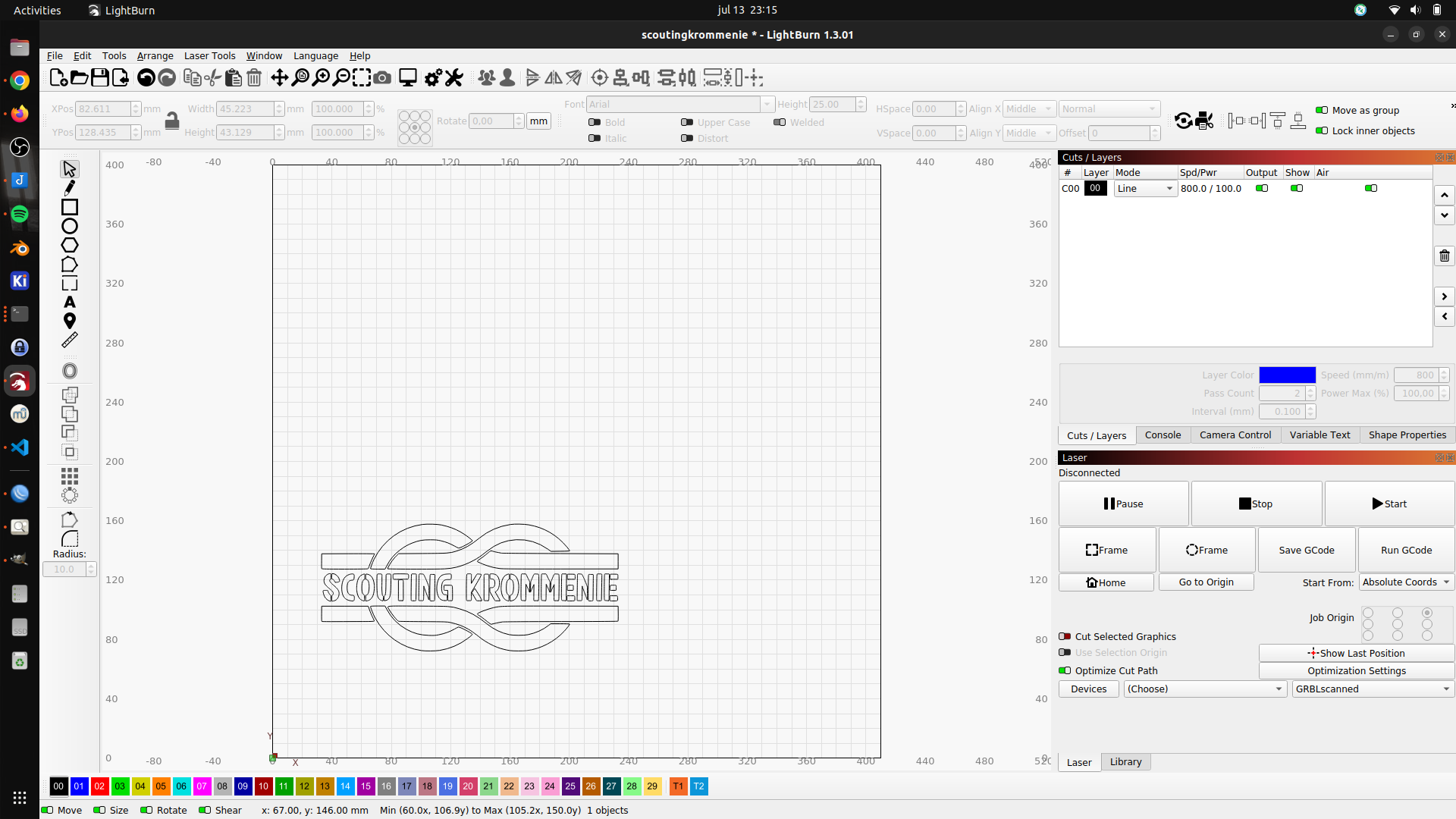
Today I got the EIStar LP-1. Its just a cheap easy probe, but does the job. My version is only TTL and this one is TTL/CMOS (cmos is better when measuring arduino’s outputs) TTL – Logic 1 = 4.75 -> 5V CMOS – Logic 1 = more around the 3.3/3.7V
Only thing my version has which i’m missing is a pulse detector. One millisecond puls gets clocked into a latch and keeps a led on.
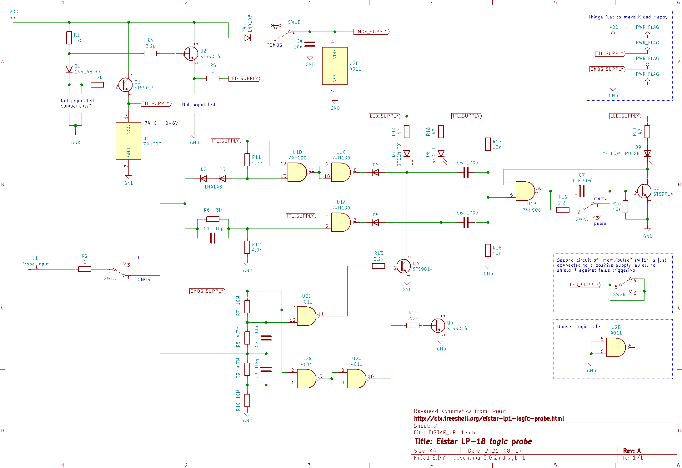
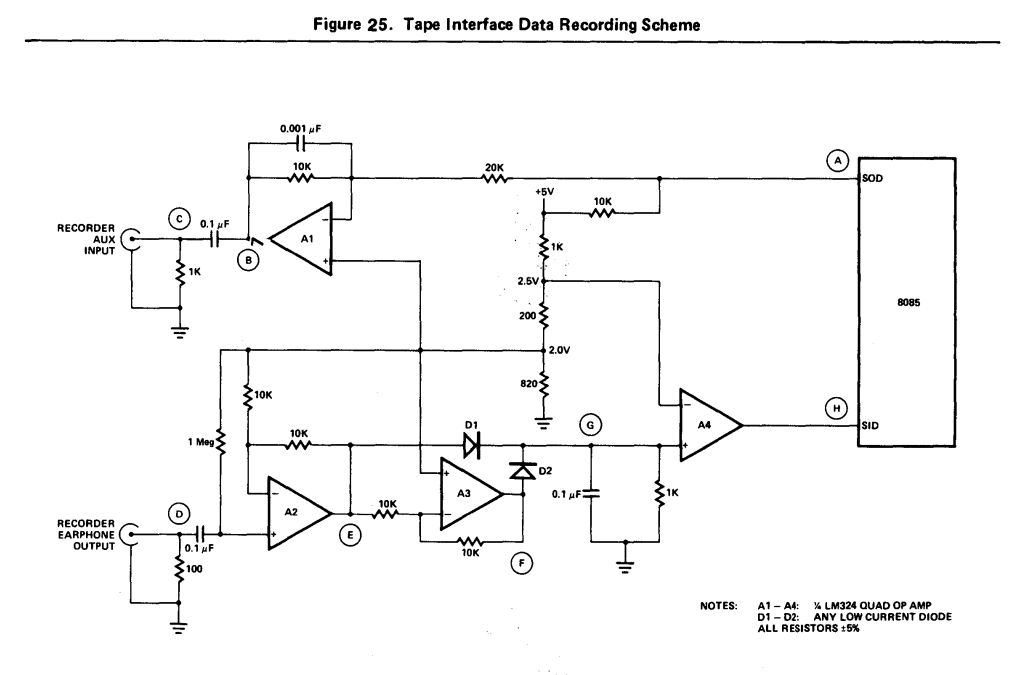
Schematic I found (some similarities can be seen with my version)
I found some parts of our (Edk and Me) bootloader demo.
It was compiled using masm or tasm. Encountering a problem converting the code into a raw bin, to put on a floppy I diverted to another setup to try to get things working.
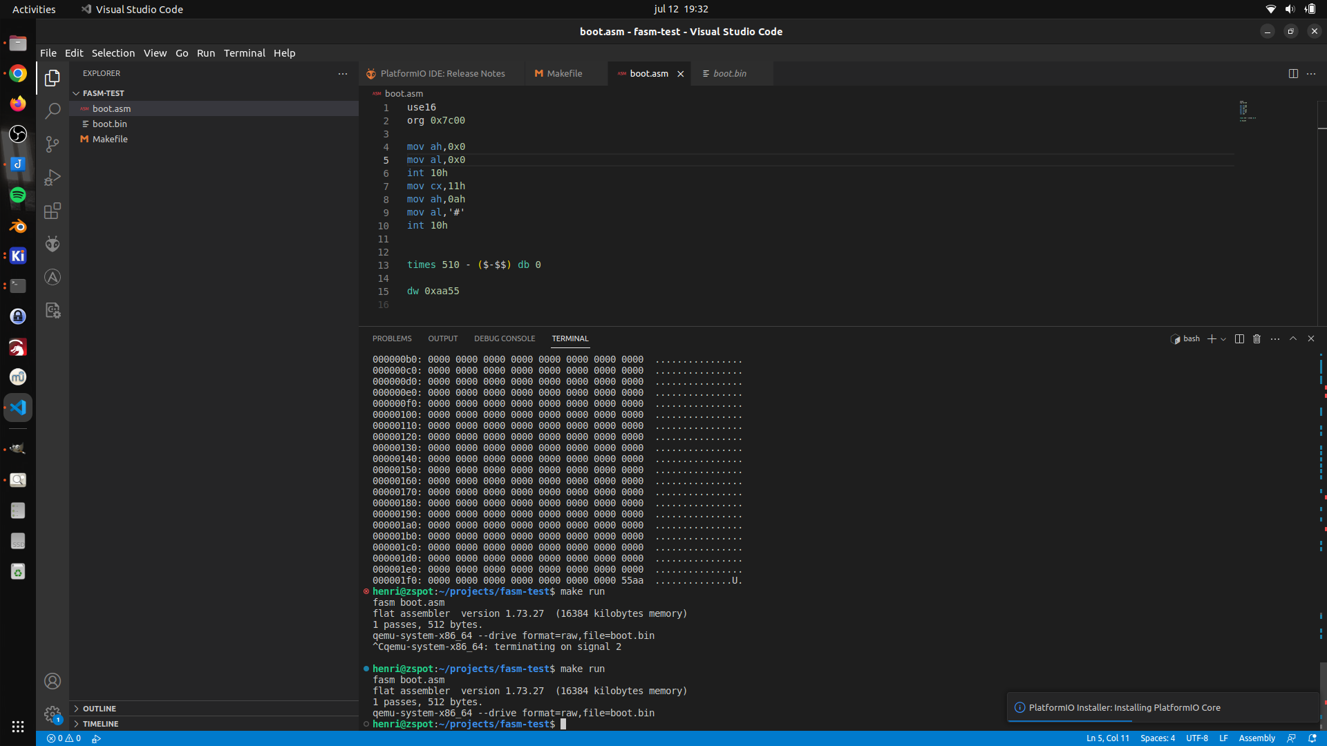
Using old code (below) and a example from YT, I made the following setup.
Visual studio code, with the x64 assembly plugin. xxd as hexviewer. fasm as assembler (This makes things easier, because it is a native Linux x86 compiler. So no need for dosbox anymore.)
;-------- snip
Start:
    JMP     SHORT BootHere
    NOP
    DB      "FASH-EDK"
    DW      512
    DB      2
    DW      1
    DB      2
    DW      0070h
    DW      02d0h       ;max. aantal sectoren van volume A
    DB      0Fdh        ;media descriptor
    DW      0002h       ;aantal sectoren per FAT
    DW      0009h       ;aantal sectoren per spoor
    DW      2
    DW      0
BootHere:
    mov     bp,5
tryboot:
    push bp
    mov     bx,4000h
    mov     es,bx
    mov     bx,0
    mov     cx,2        ;vanaf sector 2
    mov     dx,0        ;drive A, kant 0
    mov     ah,02h
    MOV     AL,8
    int     13h         ;sector(en) lezen
    pop     bp
    jnc     bootok
    dec     bp
    jnz     tryboot
bootok:
    mov     bp,5
;---------- snap
New setup using fasm (bootloader) boot.asm
    org 0x7c00                  ;  still not sure about this, have not found this in our demo

    mov bx, 0x1000              ; load sector address
    mov es, bx
    mov bx, 0x0

; Sector read function
    mov dh, 0x0                 ; head 0
    mov dl, 0x0                 ; drive 0
    mov ch, 0x0                 ; cylinder 0
    mov cl, 0x02                ; start sector

readdisk:
    mov ah, 0x02                ; read sec
    mov al, 0x02                ; demo is > 512 so 2 sectors
    int 0x13                    ; call bios

    mov ax, 0x1000
    mov ds, ax
    mov es, ax
jmpcode:
    jmp 0x1000:0x0              ; far jmp demo

; Expand bin to 512 byte sector
    times 510-($-$$) db 0
    dw 0xaa55                   ; Sector header (ROM as this at the start)
Graphics demo i wrote a long time ago, converted into fasm loadpart.asm
	mov ah,0
        mov ax, 4f02h   ; Set VESA video mode
        mov bx, 10dh    ; Your video mode number
	int 10h
	mov al,0
drawall:
	mov dx,0
	mov cx,0

drawloop:
	mov ah,0ch
	mov bh,0
	push ax
	int 10h
	pop ax
	inc al
	inc cx
	cmp cx,319
	jc drawloop
	mov cx,0
	inc dx
	cmp dx,199
	jmp drawloop
jmp drawall

; complete sector with zeros
    times 512-($-$$) db 0
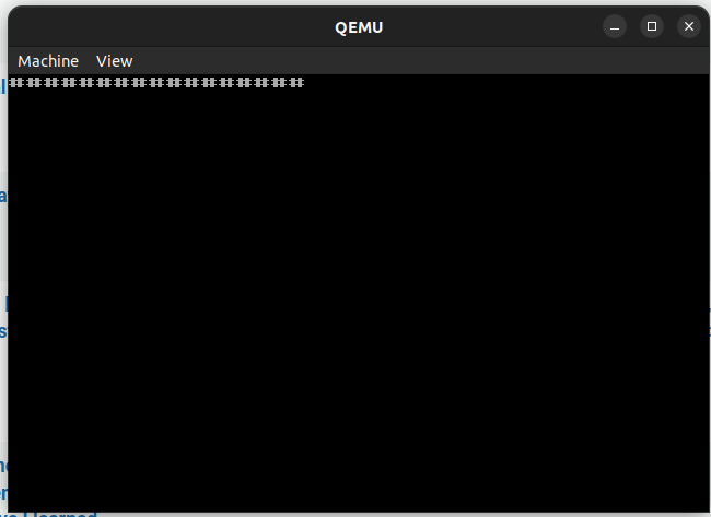
Booting the demo in milli seconds using qemu. Next to do: Write this to floppy and test on real hardware.
A reset starts the virtual machine and boots from a virtual floppy. The drawing of the pixels is slow, because I used a int 10h function for every pixel, instead of writing to screen memory directly.
Got a part working again in PCem. This is from our bootdemo. A scroller and sector loader in a bootsector. Needed some include files masm, link, exe2com creates a 12- sector sized floppy. And we’ve got a (little distorted but working) Scroller in boot sector with custom font!
font:   db 64 dup (0)       ;space
        db 0,0,2,2,0,0,0,0  ;!
        db 0,2,2,2,2,0,0,0
        db 0,2,2,2,2,0,0,0
        db 0,2,2,2,2,0,0,0
        db 0,0,2,2,0,0,0,0
        db 0,0,2,2,0,0,0,0
        db 0,0,0,0,0,0,0,0
        db 0,0,2,2,0,0,0,0
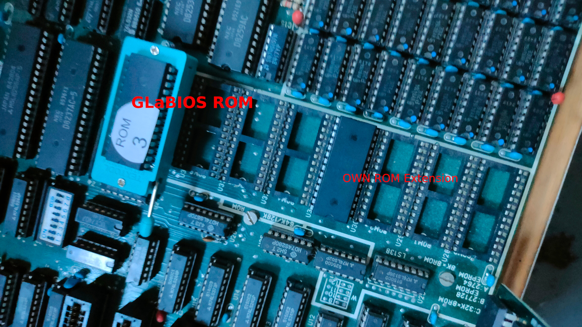
Today two boot projects. One using a bios extension, so it chip based. Second is a floppy disk boot program. (Creating a test situation to get our old Boot floppy demo working. ( That one without using an operatingsystem like ms-dos.
Creating a Secondary Bios ROM
NAME mycode
.model small
ORG 0h

.code
	dw 0AA55h ;  Magic header your bios is looking for
	db 16     ; lenght of this rom in 512 bytes == 8k
	jmp short clear ; jmp to program

ORG 20h                 ; start of program

clear:  mov cx,10       ; clear, set keyboard led and print 10 # chars
	mov ah,0ah
	mov al,31h
	int 10h
	mov bh,0
	mov cx,1
start:	mov al, 11000000b
        out 80h, al
print:  mov cx,10
	mov ah,0ah
	mov al,"#"
	int 10h
loop1:  nop           ; loop until doomsday
	jmp loop1
	db -68        ; This makes the checksum 0
                      ; steps to take: edit source, make this byte entry 0
                      ; compile using make.bat in dosbox
                      ; check checksum using my python script
                      ; output was 68 hex 0x44
                      ; edit asm file place -68 to make the checksum 0x00 again
                      ; compile and burn to ROM
ORG 2000h             ; create end of rom 0000h-1fffh = 8K
END
make.bat in dosbox
@ECHO OFF
MASM /DARCH_TYPE="T" /DCPU_TYPE="V" 1;
LINK 1;
EXE2COM 1.EXE
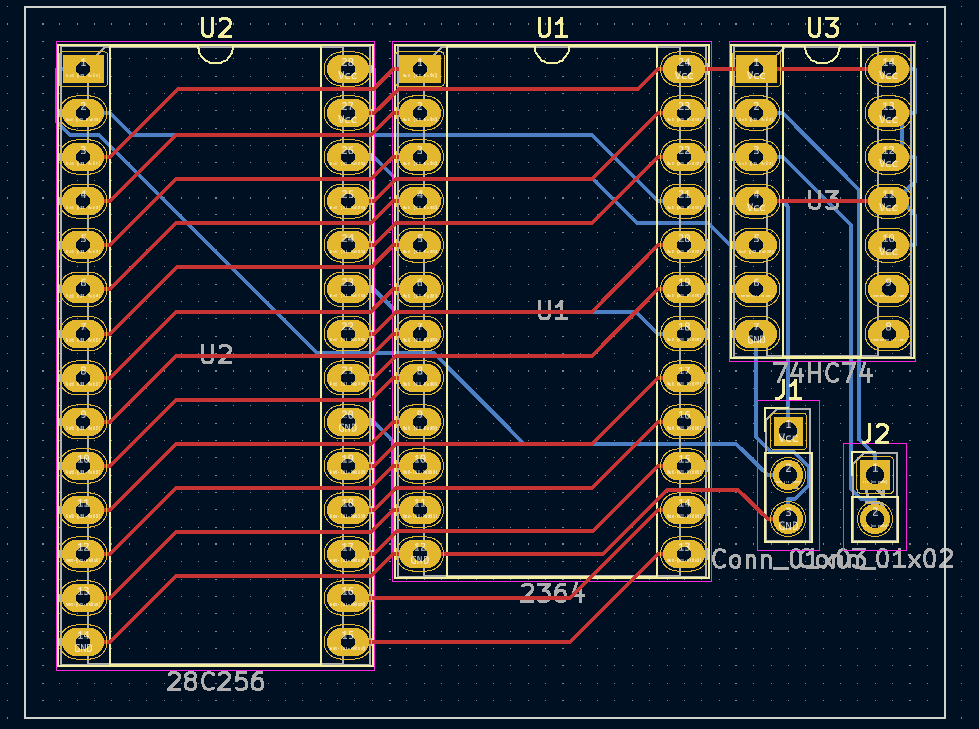
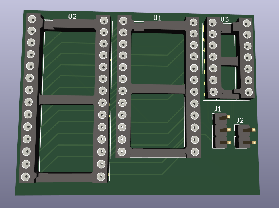
Below board replaces 2364 (8k) with a 28c256 (32k 4 roms) socket. My design in Kicad
The rom can be selected using the pressing restore while starting the C64. ( This button press to select is not my idea but I liked it, when I find the original idea I’ll post it.
After ordering and testing, I’ll attach the Gerber files.
If you are a old friend/colleage/whatever .. give me a ping to get you connected.
I’ve been using IRC a long time, we even had our own interconnected servers with our group ICE. Lipperkerk, GMC and Pixnet. Overkill I know, but we could so we did.
Last few years i’ve been using Mattermost. After testing many alternatives.
Whatsapp – not own hosted, hate it, and was not allowed for work.
Zulip – tested this for a long time
IRC at work, implemented this at 2 places i’ve worked. Once using a web gui.
A ajax chat server
??
??
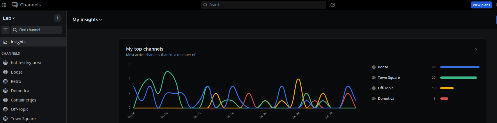
After installing this in my Lab, a few colleages from work used it. After that the whole department and more. Running for more than a year, it was time got get this running on the servers at work. I’ve reinstalled a server for my friends.
Last update gave me a nice insights desktop. Quiet days in june.
I love the webhooks and plugins.
In the past i’ve implemented a whatsapp to mattermost bridge, i will post about this .. sometime.
Below a implementation using a arduino and a 3D printed flag.
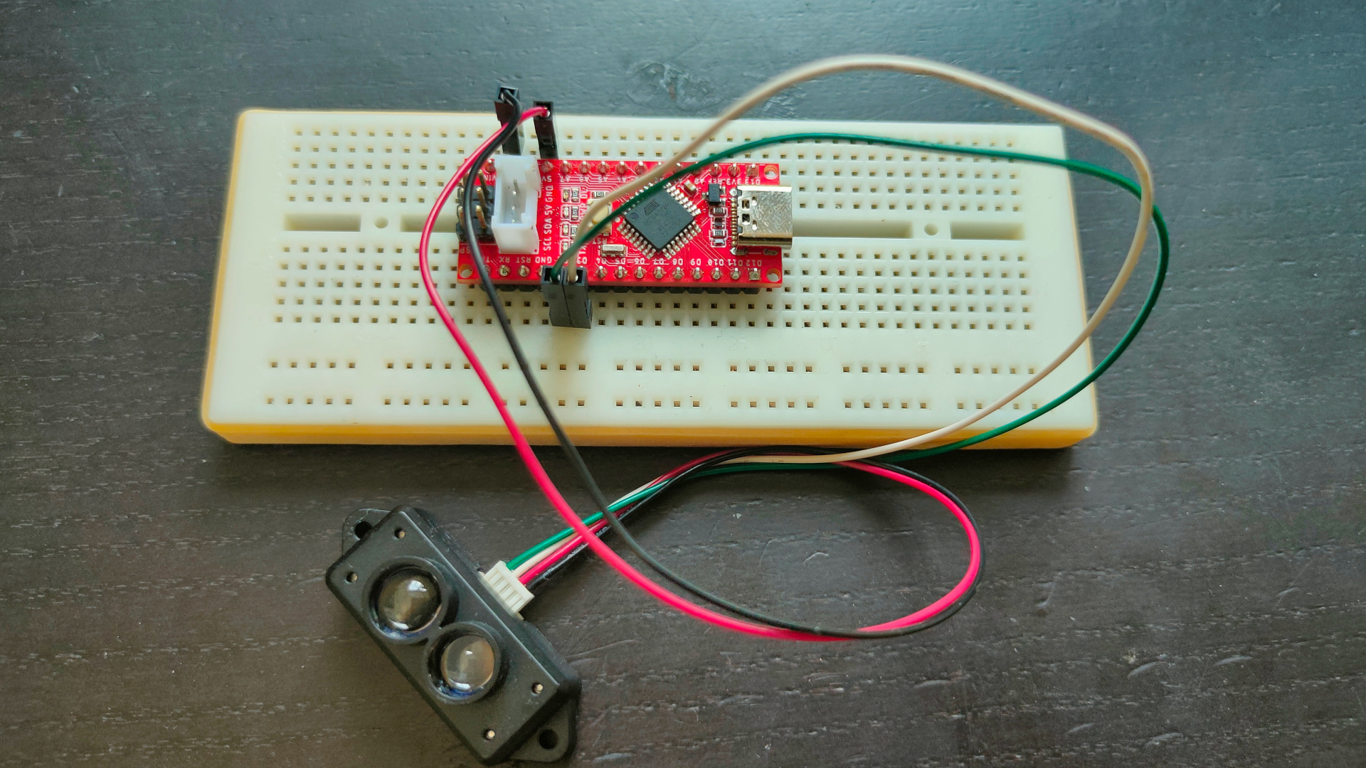
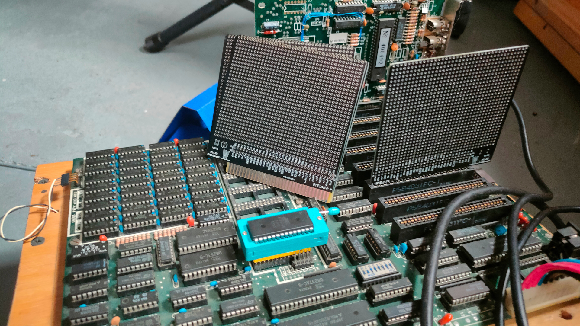
While working on a Lidar project, my mouser components came in.
Now I have to find a IO address decoder schematic I made a while ago.
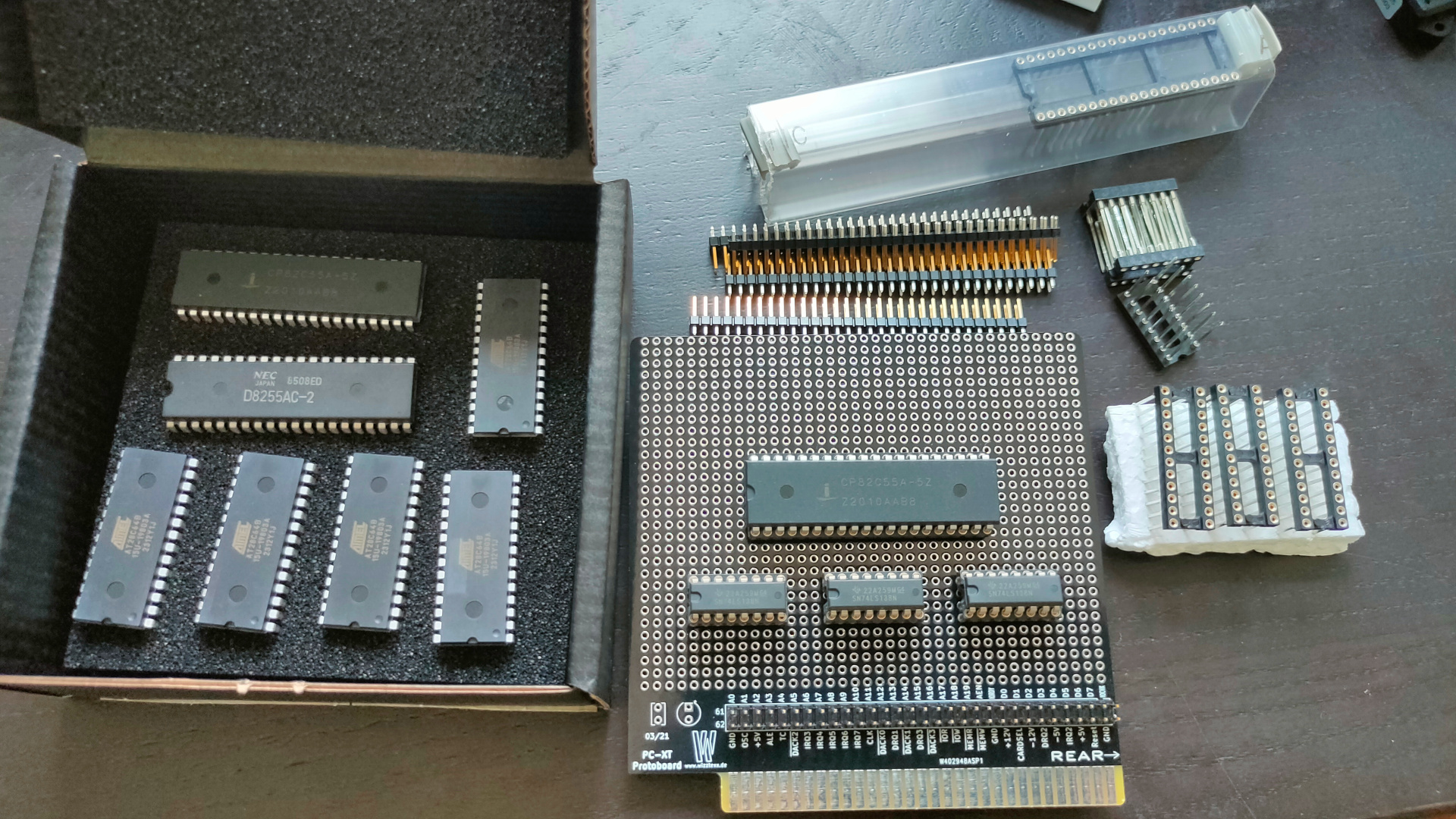
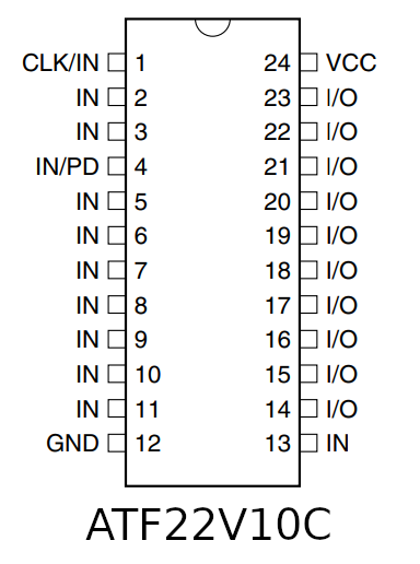
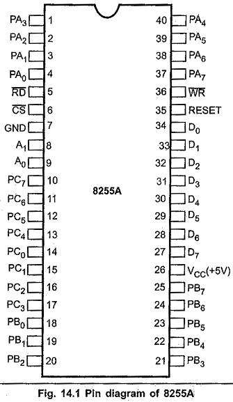
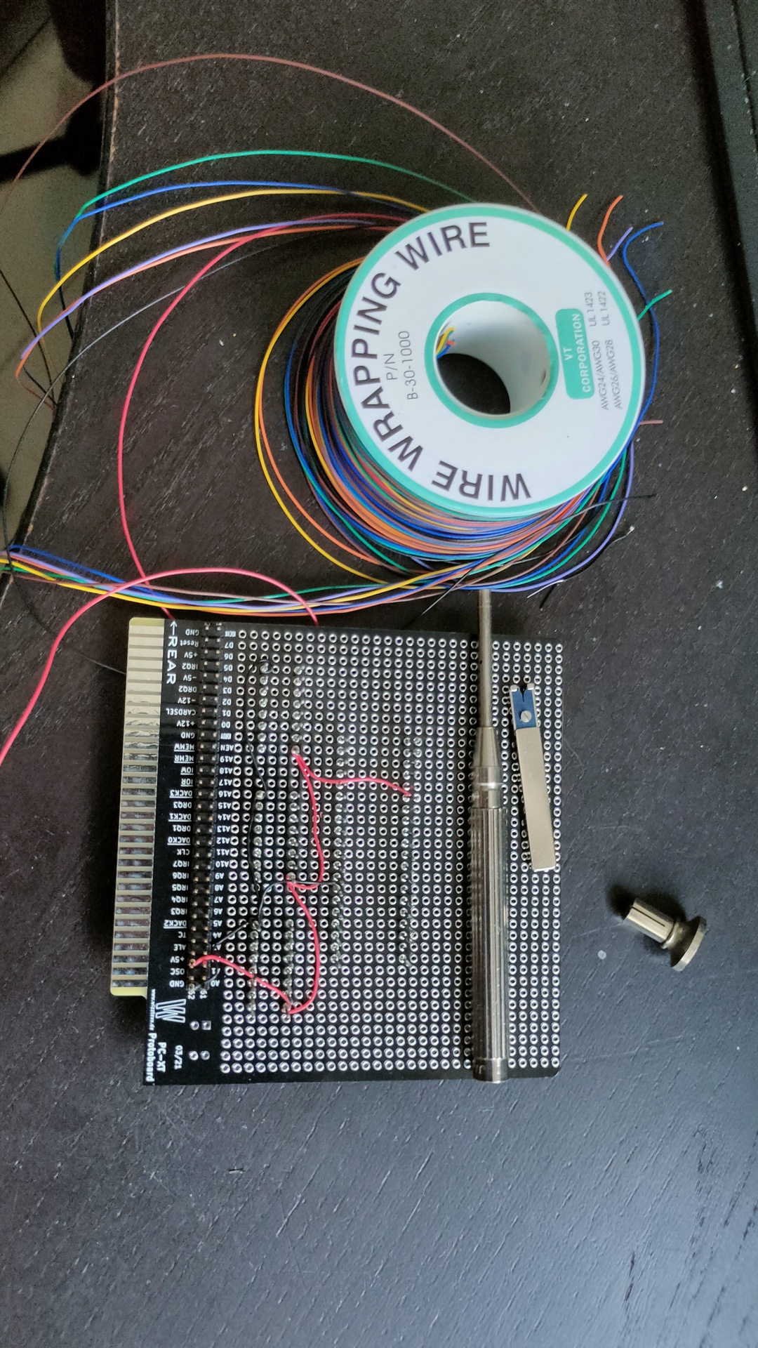
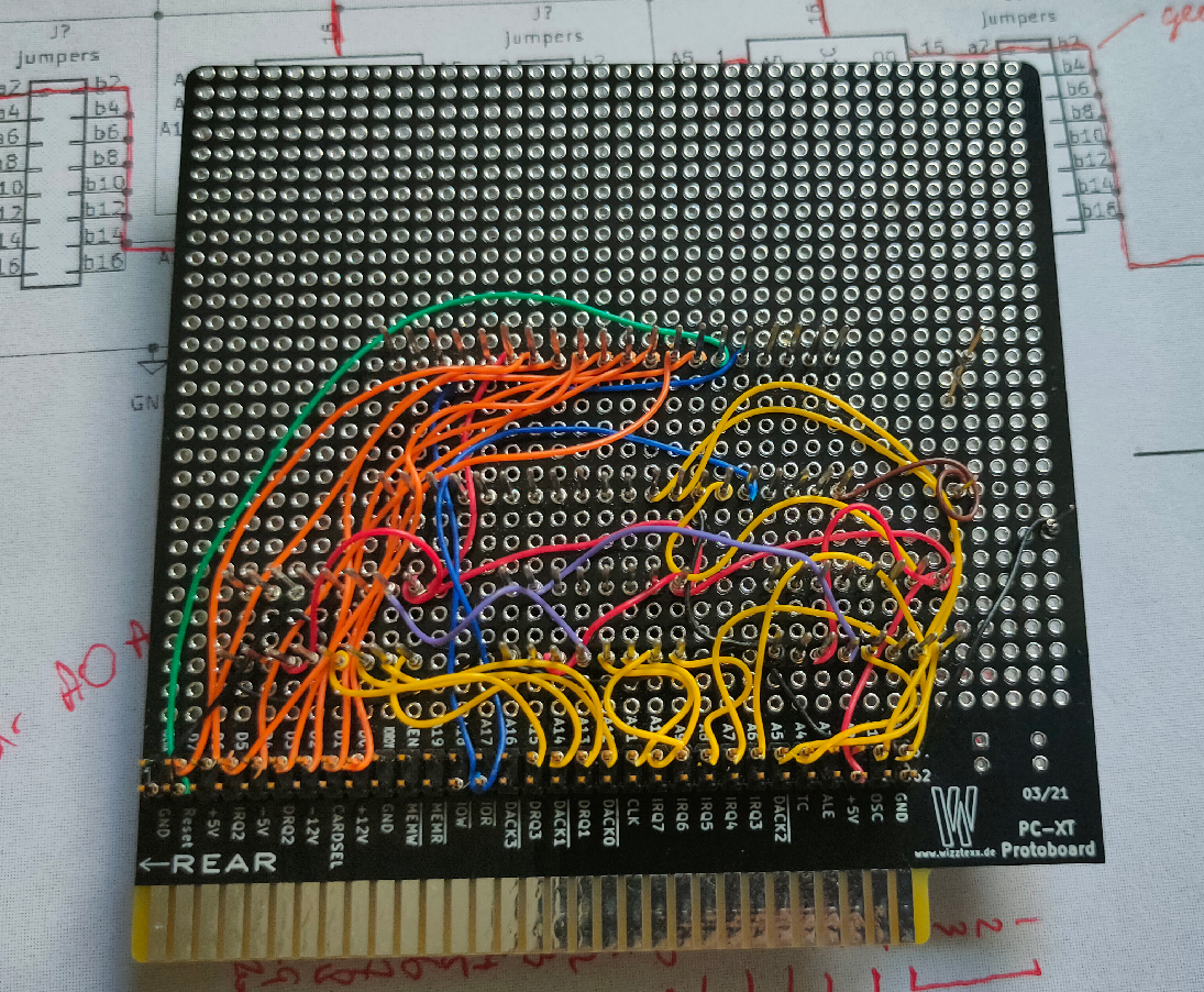
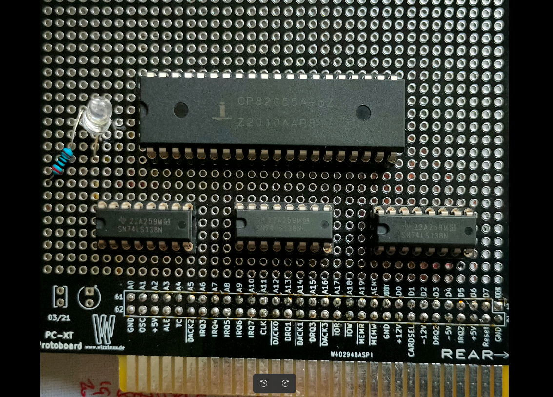
This ISA board is going to have a Wirewrapped setup. There is a 8255 IO chip, and uses 3x 74138 for IO address decoding, OR i will use a setup i’ve made for my 6502 using an atf22v10.
What to controll using this 8255? First some Leds, later a LCD display.
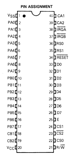
Below the 3 mentioned IC’s
The 8255 is a chip like the 6522 used in my DIY 6502 elsewhere on my site.
Overview of comparable IO chips. ( Not interchangeable due to bus timing!) Most of them have 8 data lines and 2x 8 IO bi-directional lines.
CHIP
NOTES
6522
6502 based machines
8255
8088/8068 based machines
Z84C2008
Z80 (called PIO)
8155
8085 / 8088
8520
68000 amiga
6821
6800
6821 example
UPDATE 20230702
Started wirewrapping, luckily i’ve got a big choice of colors. That makes finding the right signals a breeze.
UPDATE 20230703
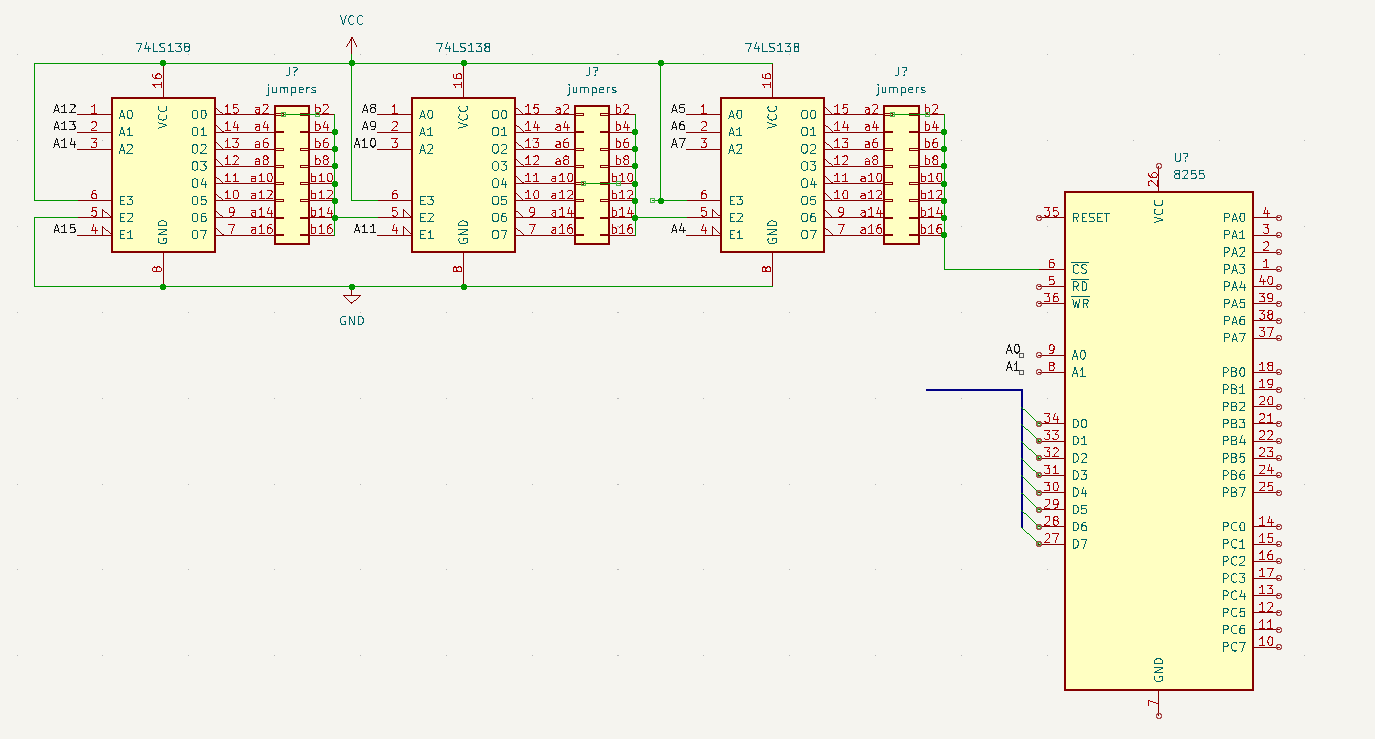
Found my schematic
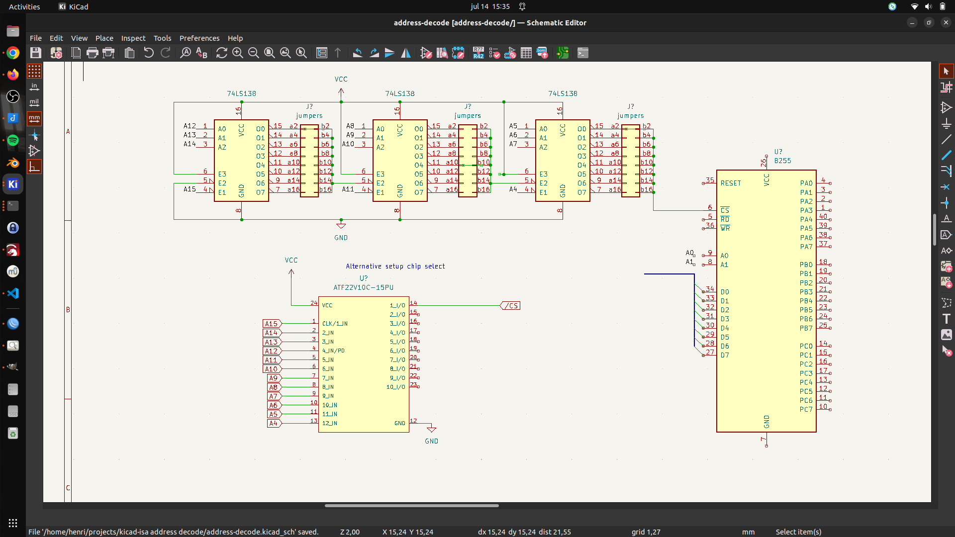
Above uses 3 74138 decoders, address can be “programmed” using jumpers (not used on my prototype board) . Address 0400h in above example.
A15 – 0 A14,13,12 – decodes to OUT-0 A11 – 0 A10,9,8 – decodes to OUT-4 A7 – 0 A6,5,4 – decodes to OUT-0 A3 and A2 are not used (see note) A1 and A0 are register select on the 8255
Address 0000,0100,0000,xxrr xx can be a 0 or 1 the 8255 can be controlled using 0400h 0401h 0402h but also 0404h 0405h 0406h 0408h 0409h …. 040Ch ……
UPDATE 20230714 – Alternative address decode test with ATF22V10
UPDATE 20230803
UPDATE
Miswired second 74138. Tested with below code
mov dx,503h # control register
mov al,80h # output port a,b,c as standard IO/output
out dx,al # 16 bit IO mapped IO out
mov dx,500h # data register
mov al,0  # 0/ff all on/all off
out dx,al