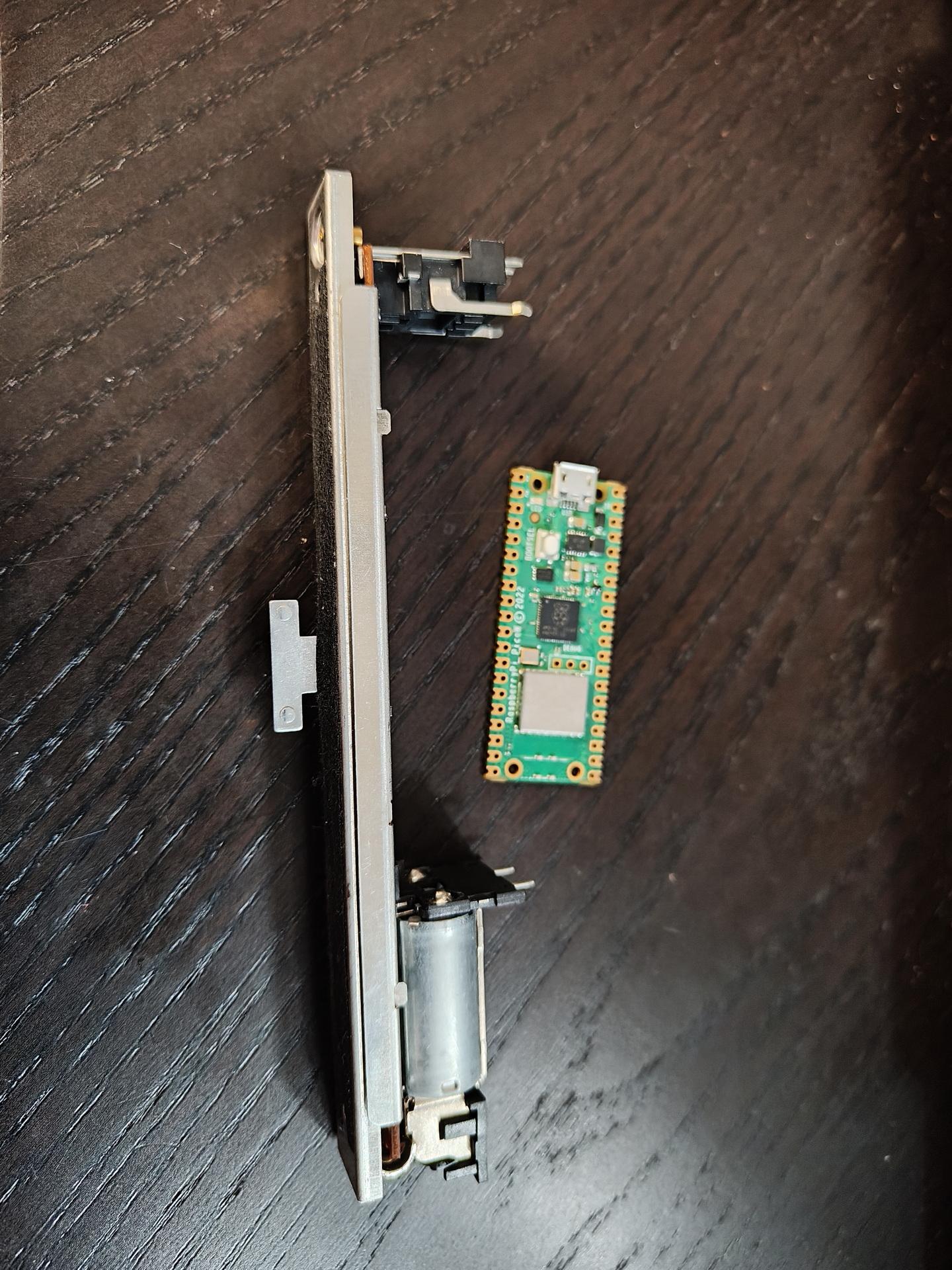
PC Volume control using motorized potentiometer. Sends state to PC using media buttons (HID-device) Uses python script to update pot position. Probably replace Raspberry Pico with Arduino Pro
Maze Wars (1970s) in javascript using MQTT backend for multiple users
substitutions:
  name: usb-relay
  friendly_name: "USB Relay"
  default_state: "RESTORE_DEFAULT_OFF"


esphome:
  name: xyusb1
  friendly_name: xyusb1

esp8266:
  board: esp01_1m

# Enable logging
logger:

# Enable Home Assistant API
api:
  encryption:
    key: "ndm8xxxxxxxxxxxxxxxxxjlvrggJv3a1BkY="

ota:
  - platform: esphome
    password: "12cc9xxxxxxxxxxxxxxxxfb6a01e672"

wifi:
  ssid: !secret wifi_ssid
  password: !secret wifi_password

  # Enable fallback hotspot (captive portal) in case wifi connection fails
  ap:
    ssid: "Xyusb1 Fallback Hotspot"
    password: "xxxxxxxxxxx"

captive_portal:

time:
  - platform: homeassistant

# Blue LED
status_led:
  pin:
    number: GPIO16

# Relay
switch:
  - platform: gpio
    id: switch_relay
    pin: GPIO5

  # Green LED
  - platform: gpio
    pin: GPIO14
    id: green_led
    inverted: true # start on

  # Switch template to link relay and green LED states
  # LED is on when relay is off
  - platform: template
    id: relay
    name: "${friendly_name}"
    lambda: |-
      if (id(switch_relay).state) {
        return true;
      } else {
        return false;
      }
    turn_on_action:
        - switch.turn_on:
            id: green_led
        - switch.turn_on:
            id: switch_relay
    turn_off_action:
        - switch.turn_off:
            id: green_led
        - switch.turn_off:
            id: switch_relay

# Button
binary_sensor:
  - platform: gpio
    id: hardware_button
    pin:
      number: GPIO04
      mode: INPUT_PULLUP
      inverted: True
    on_press:
      - switch.toggle: relay

# WiFi Signal Sensor
sensor:
  - platform: wifi_signal
    name: "WiFi Status"
    update_interval: 60s

# Restart button
button:
  - platform: restart
    name: "Restart"
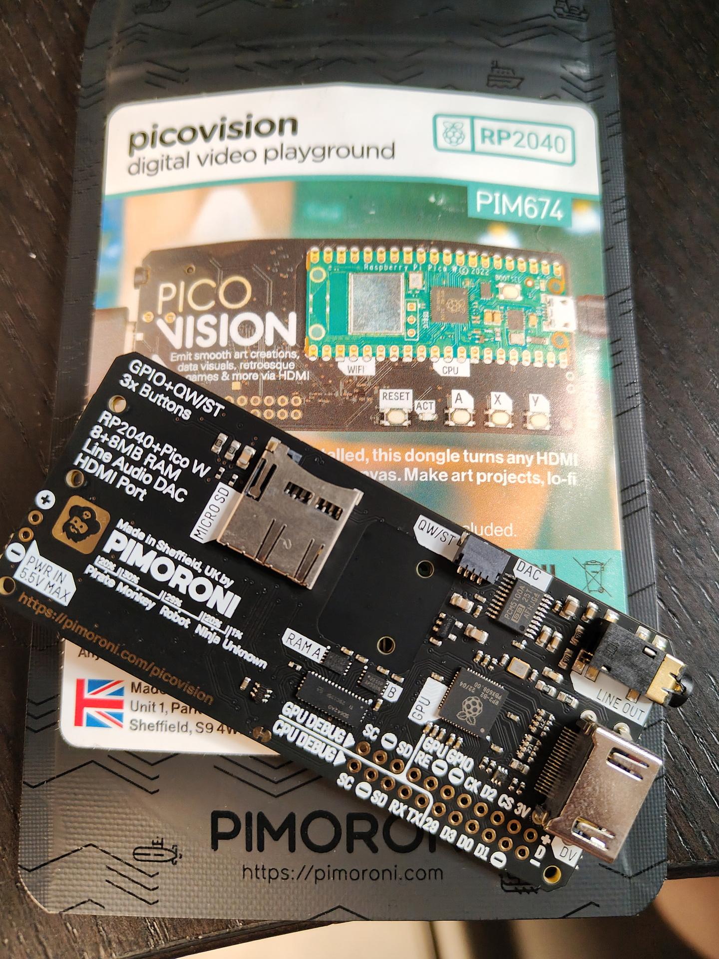
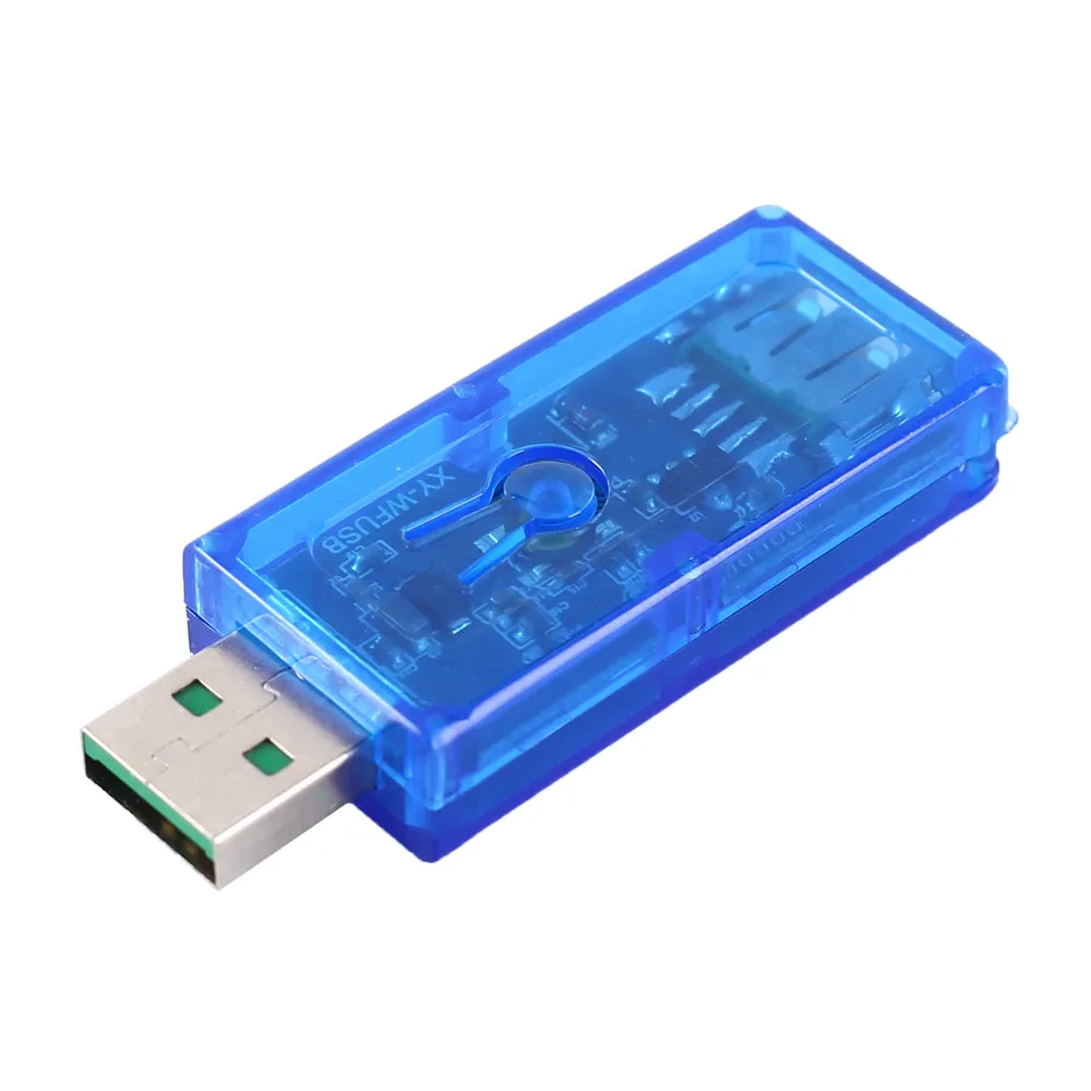
Reflashed my USB Volume button and added a LED-Ring.
Example is green and blue.
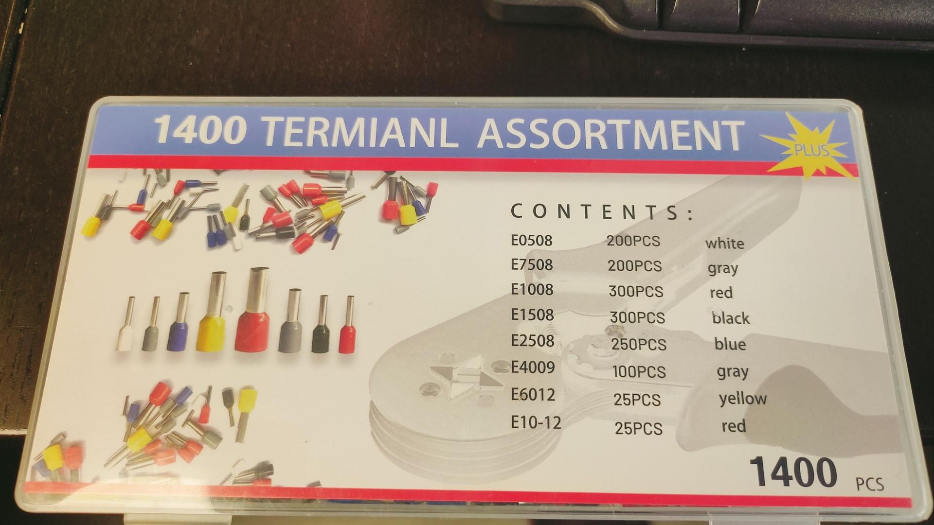
Funny text on box
What is a termianl assortment? LOL
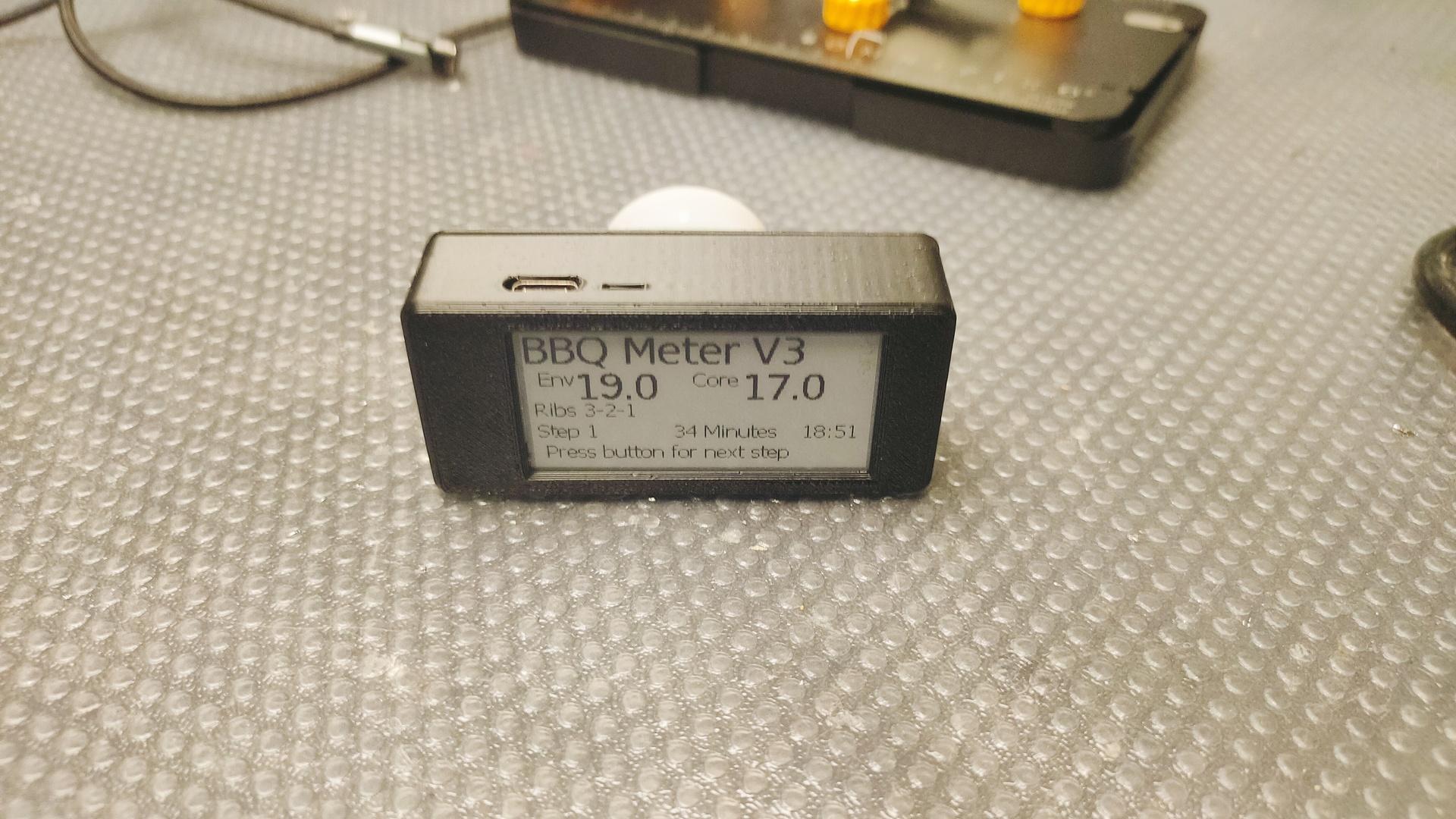
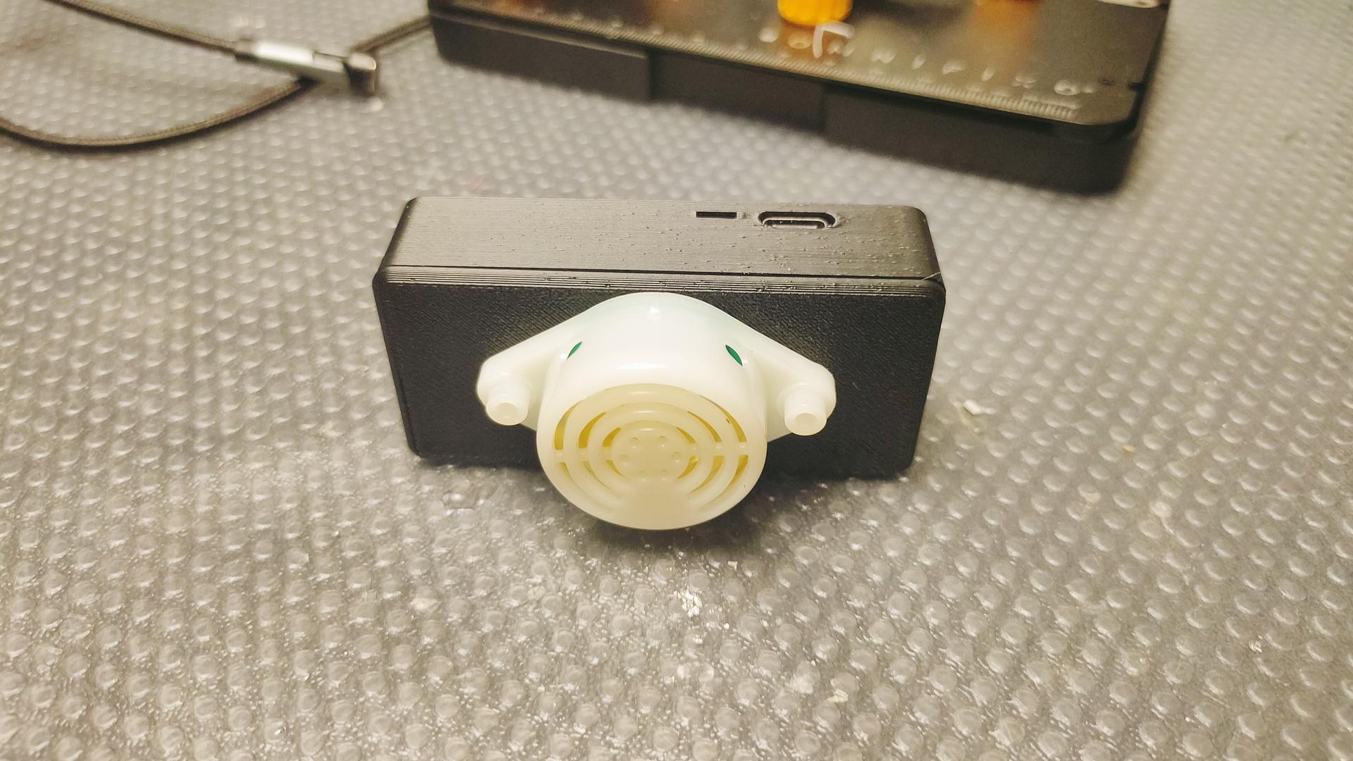
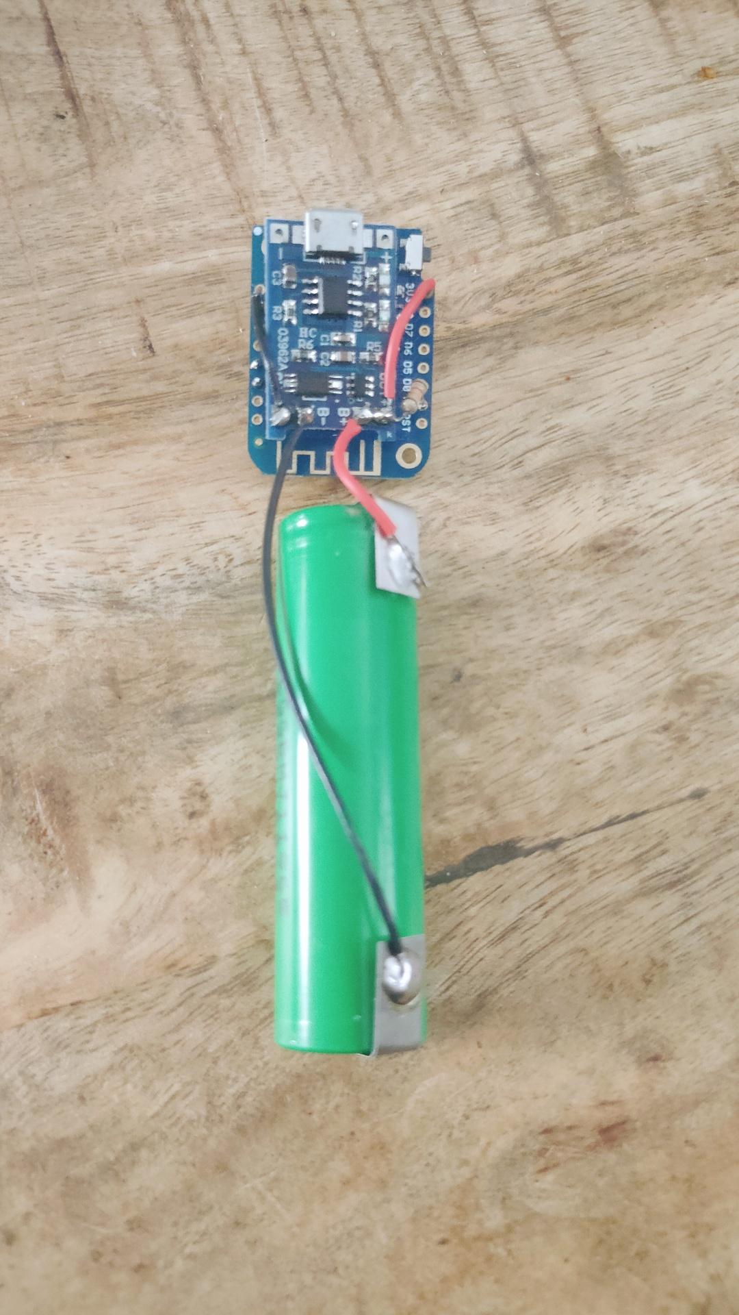
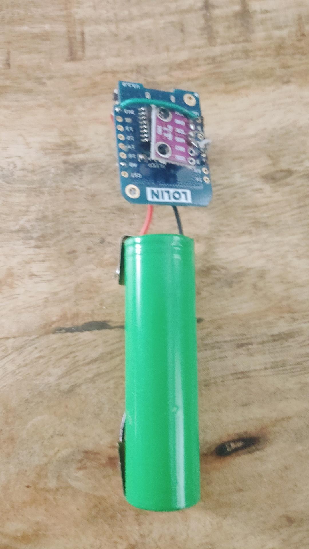
Wireless Temperature/Humidity sensor for ESPHome.
Wemos D1 mini with deep sleep, voltage monitoring using A0 line. BME280 Temperature/Humidity sensor. And a 18650 battery with TP4065 battery manager. Now 3D print a little case.
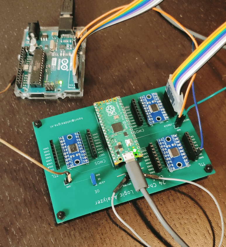
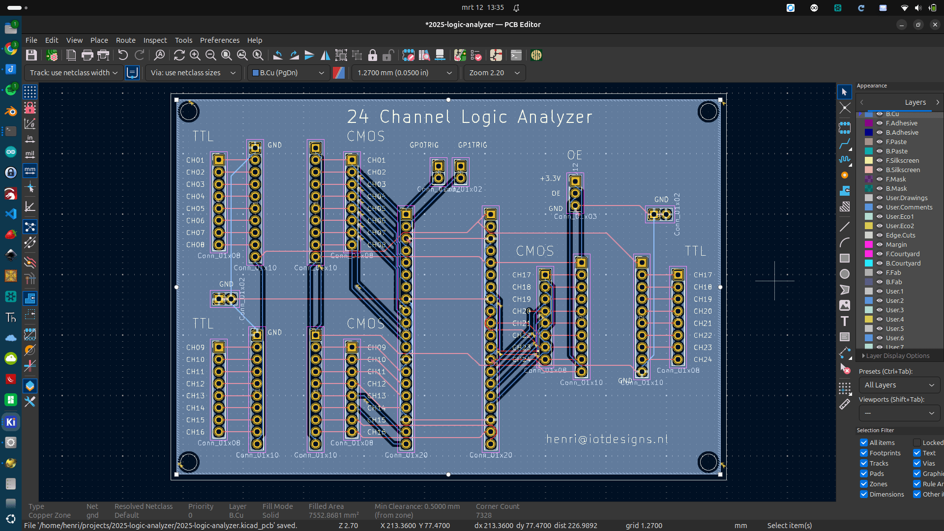
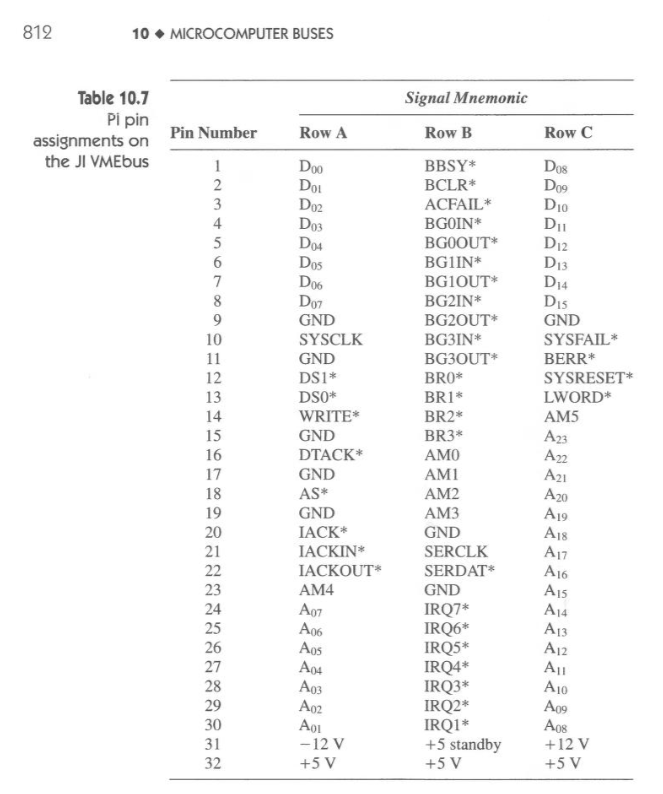
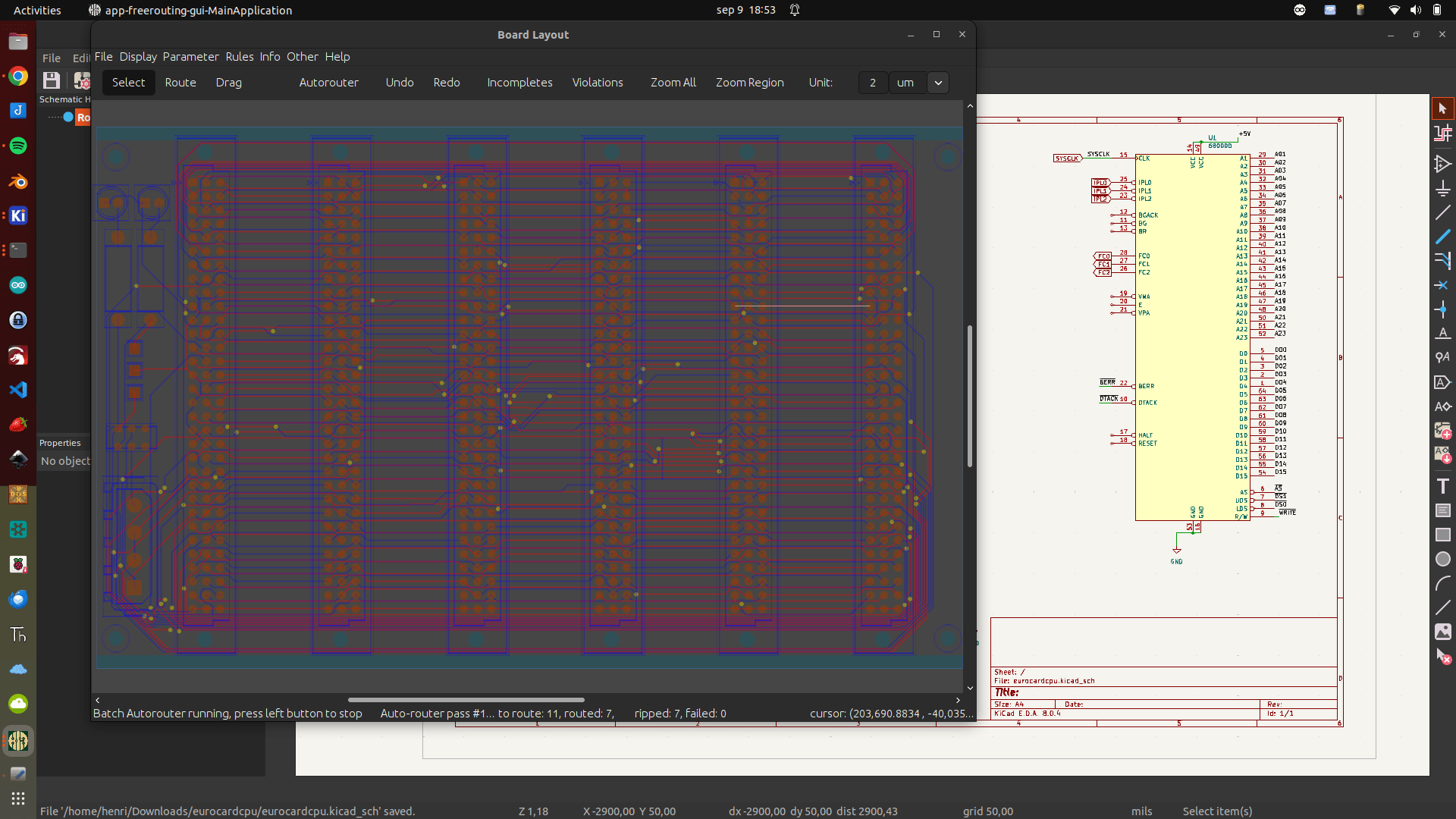
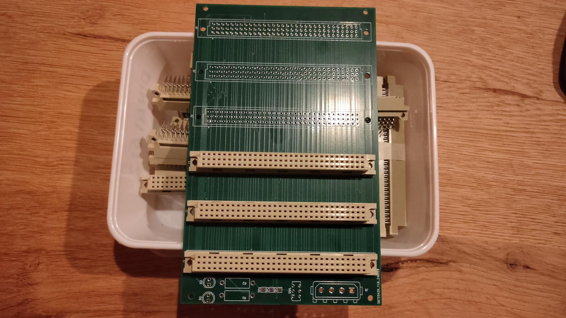
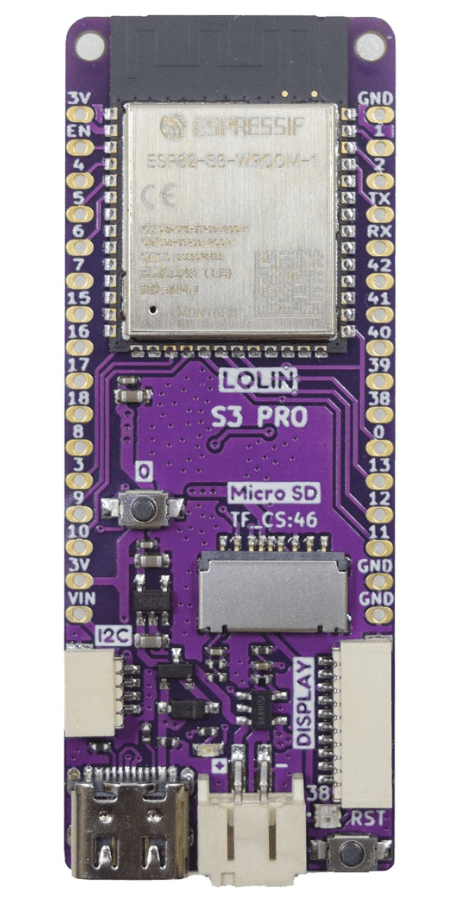
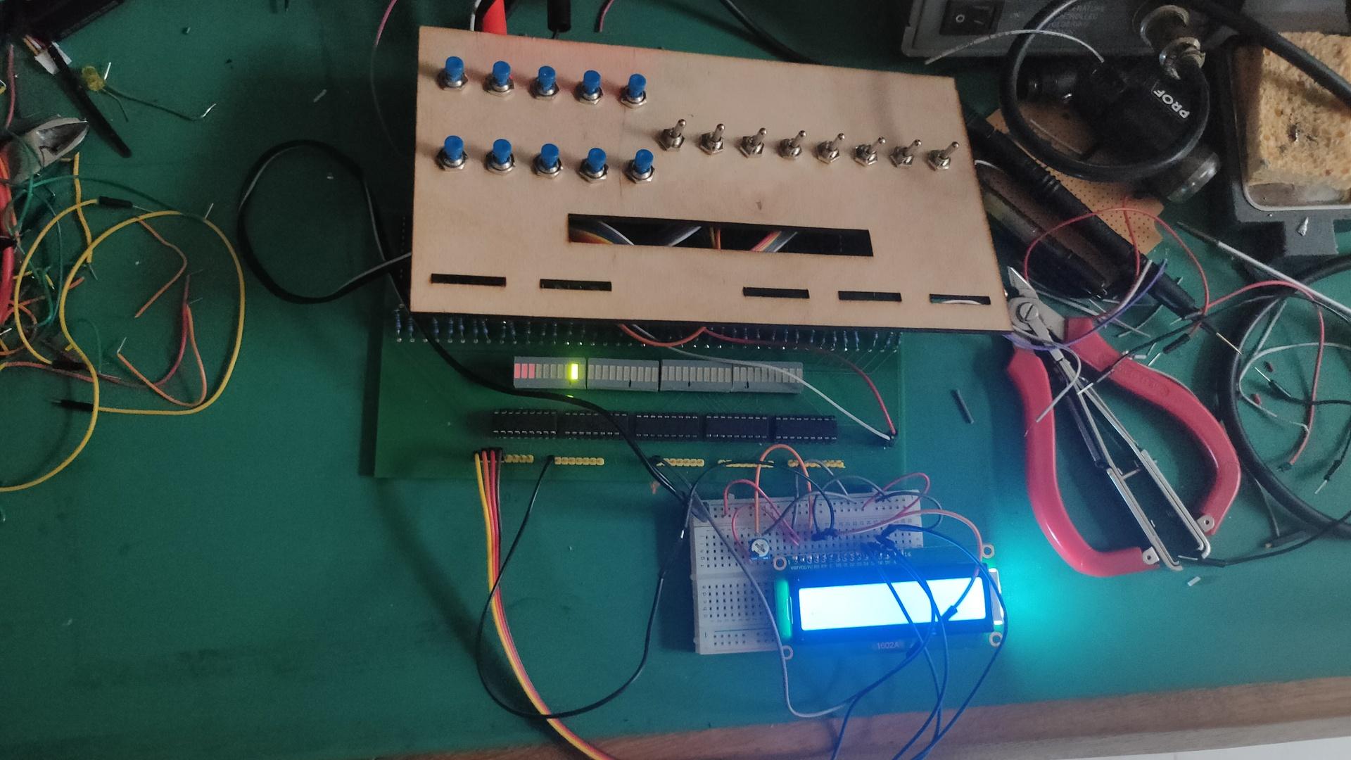
While testing on a breadboard is fast, I still want my 68000 on PCBs.
Breadboards are nice for testing, and I use them in the design stage. But they will fail in the end. Loose wires, oxidated contacts and alike.
So when I was testing using breadboard, I drew the schematics in KiCad.
I wanted to use Eurocards for this one. If I divide the whole system in system blocks, I can exchange and experiment parts. (My 6502 uses another method to connect different cards)
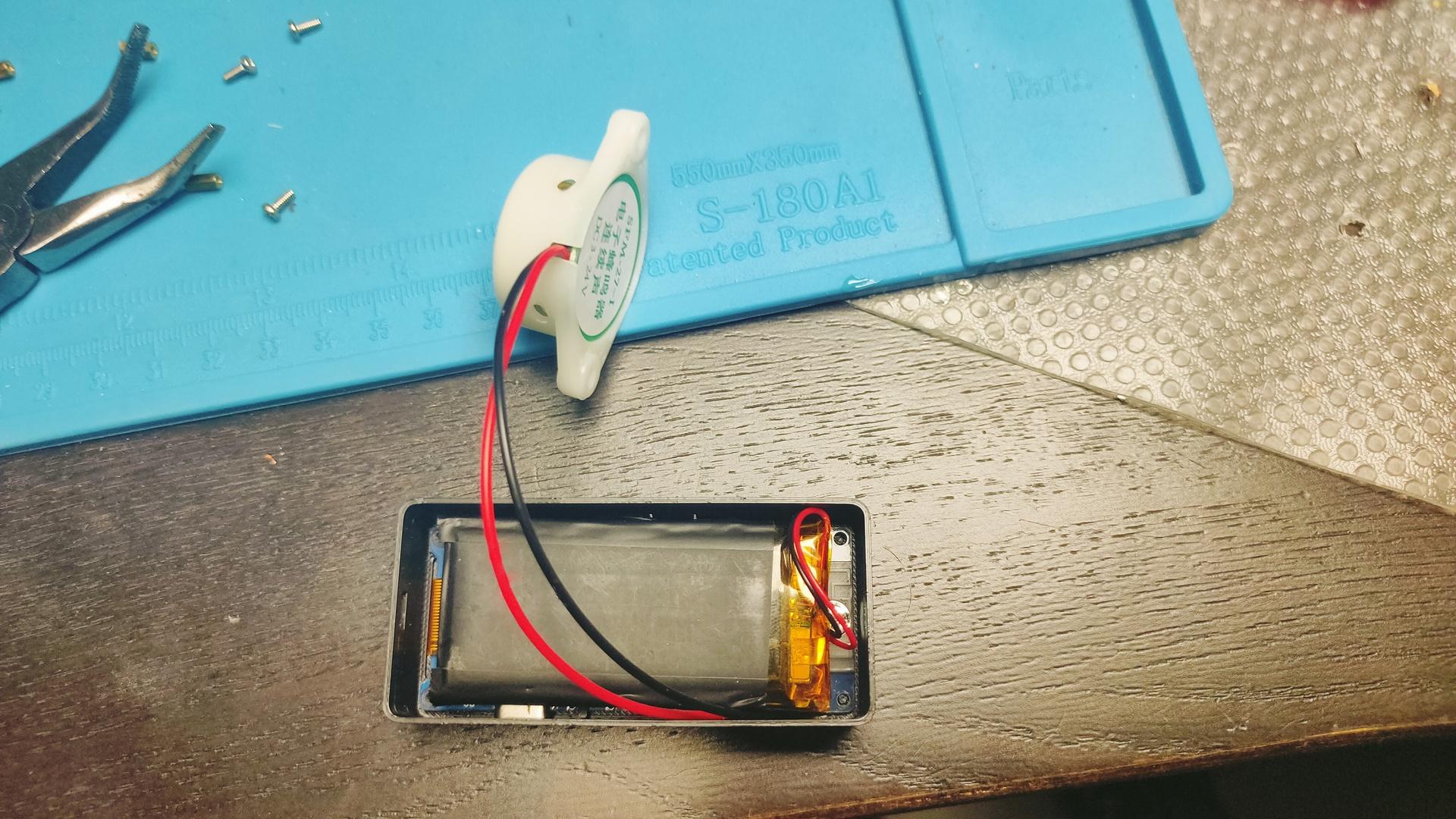
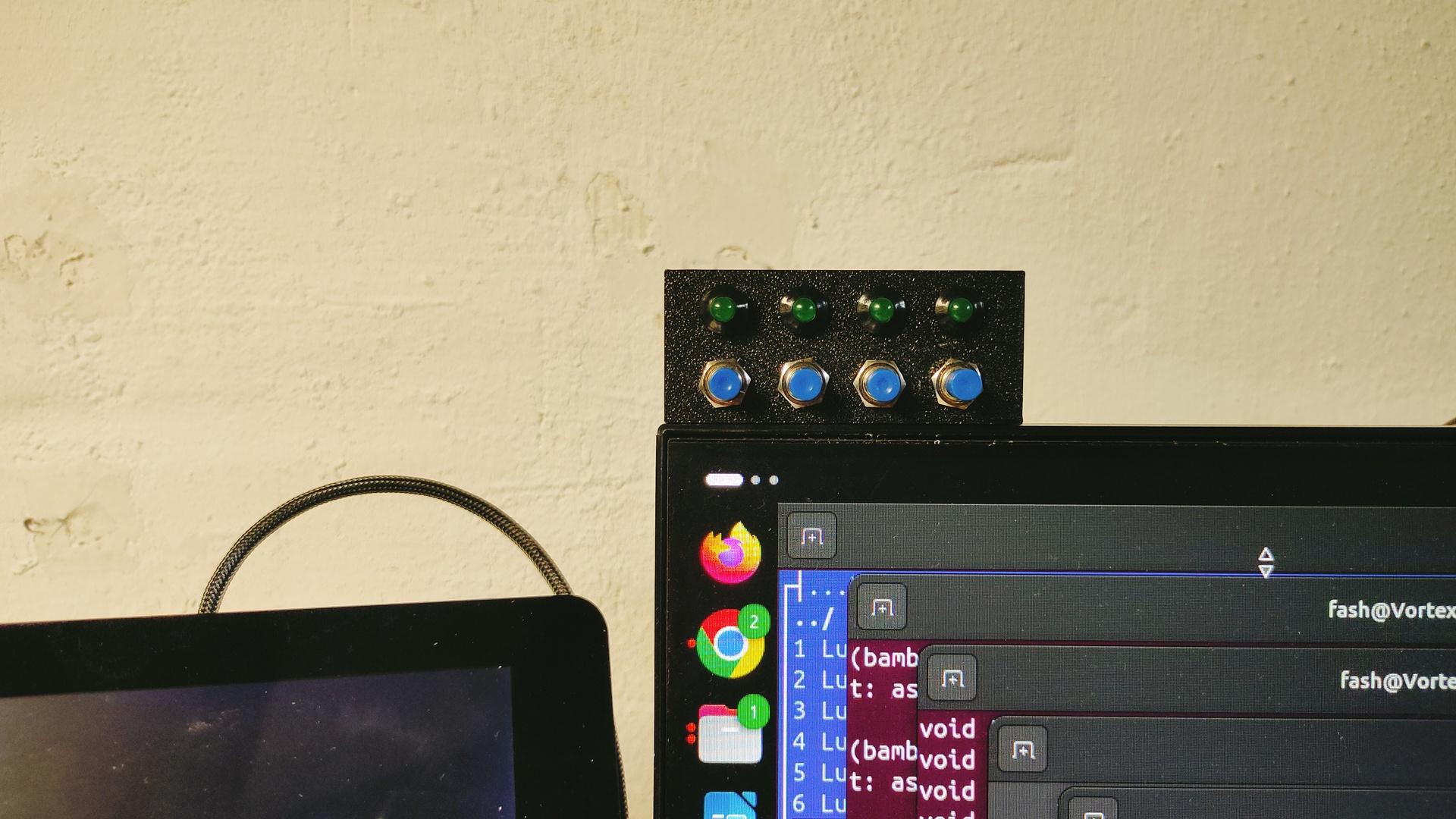
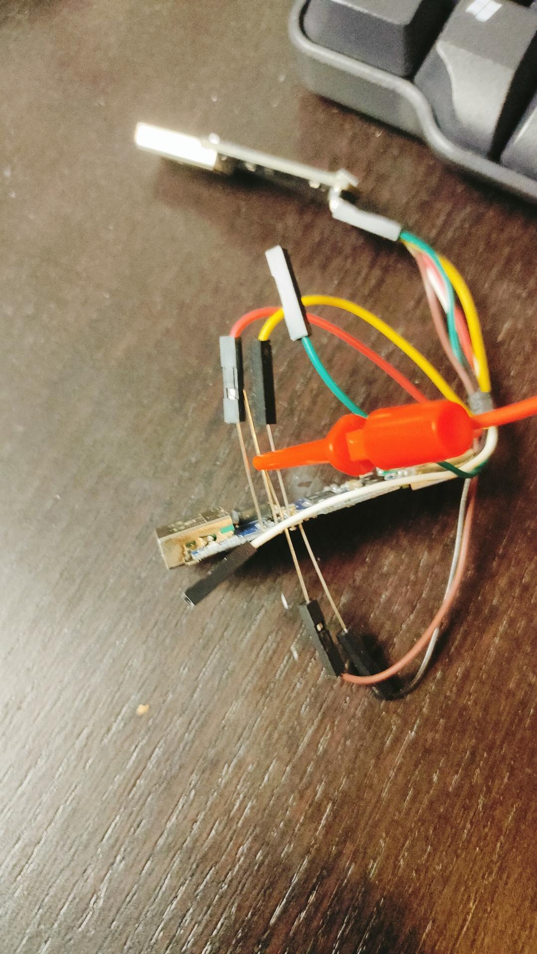
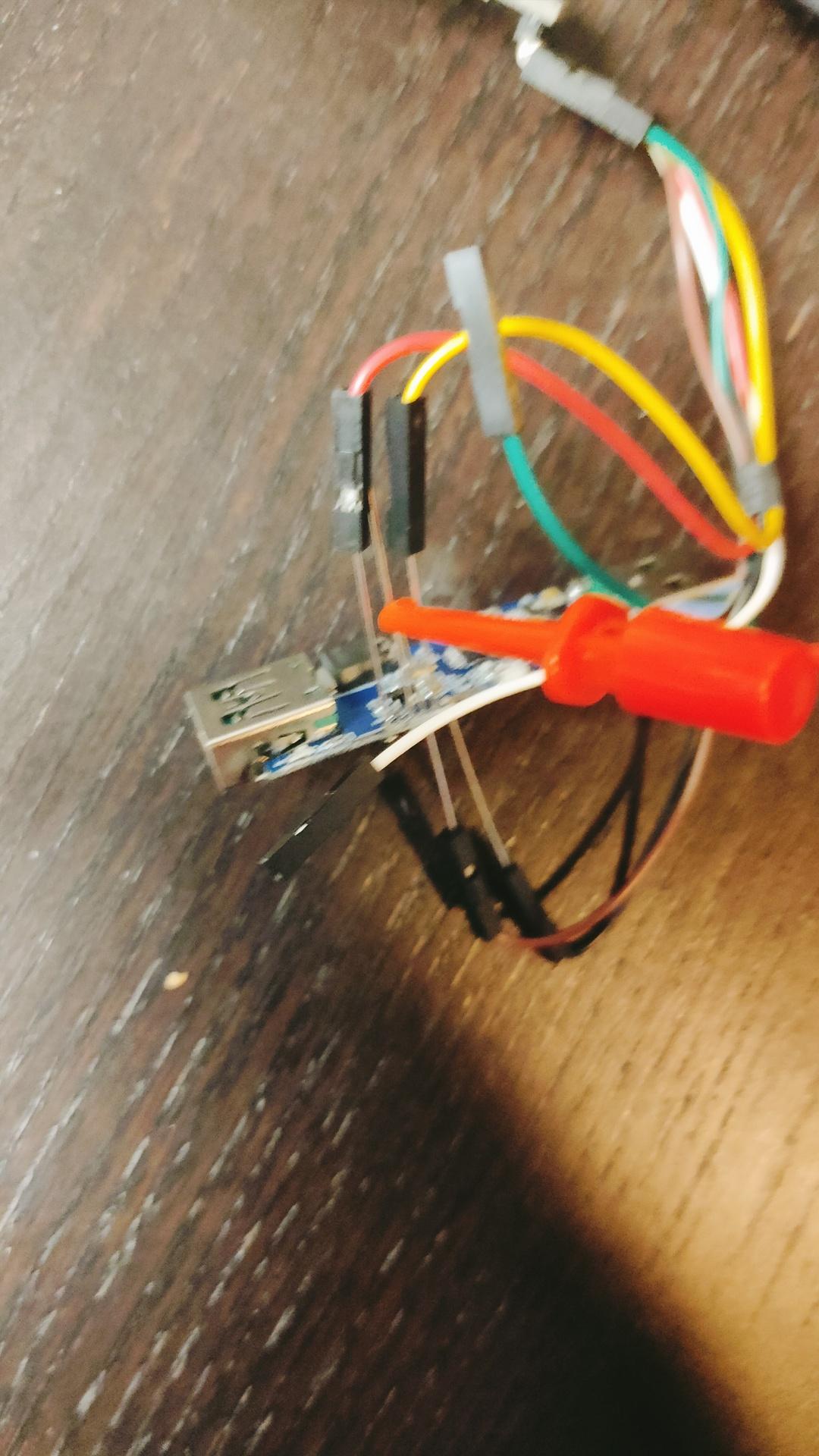
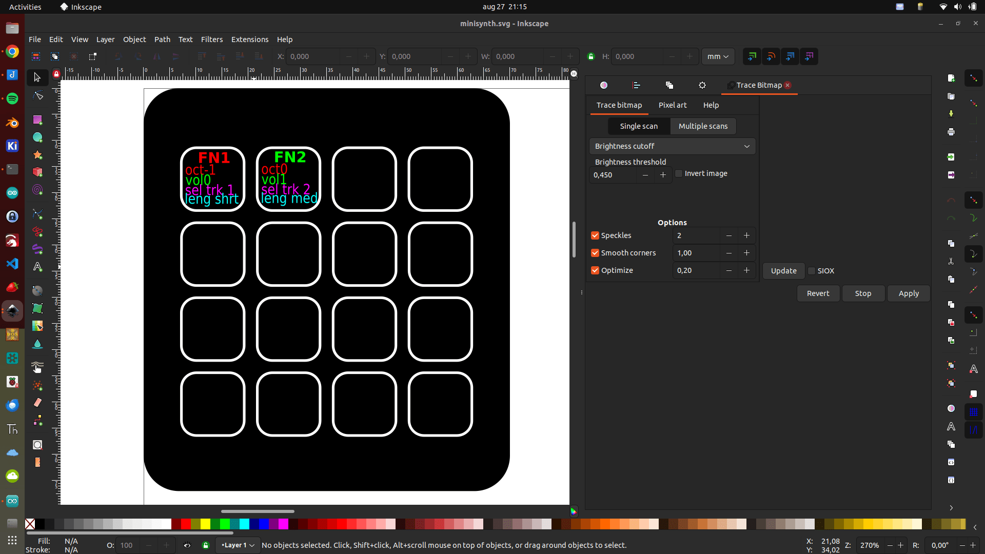
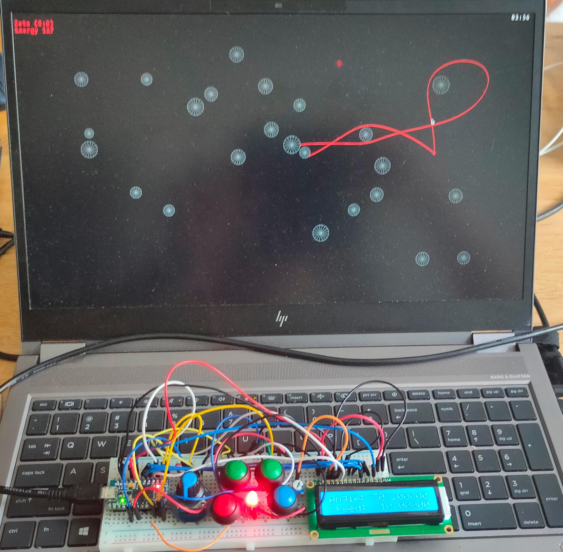
Saw a cool game a while ago, and found some old code. There was no schematic, so I had to reverse engineer it using the Arduino code. This one uses a Micro Pro.
Build a working version, now I can use this as base to create other games. But first i’m going to rebuild it so it can use Wifi and uses a Lipo Battery. Making it usable without wires.
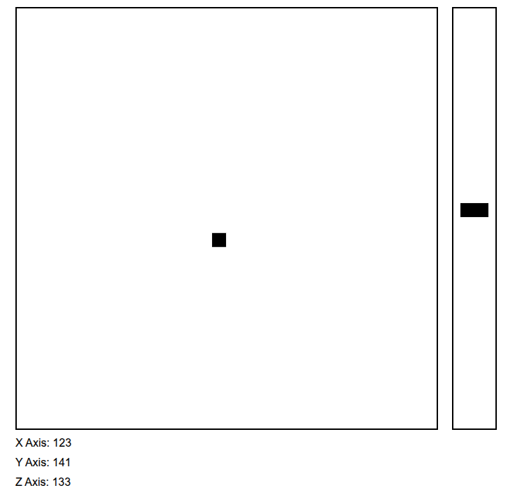
Rotary – set angle/speed (Press resets)
Blue – toggle angle or speed ( was rotary press )
Green – select digit to change
Red – Fire
Led – not completely working yet, shows color of player Wil be changed to addressable leds with more functions (Player color, energy warning and more)
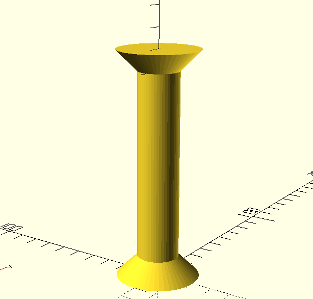
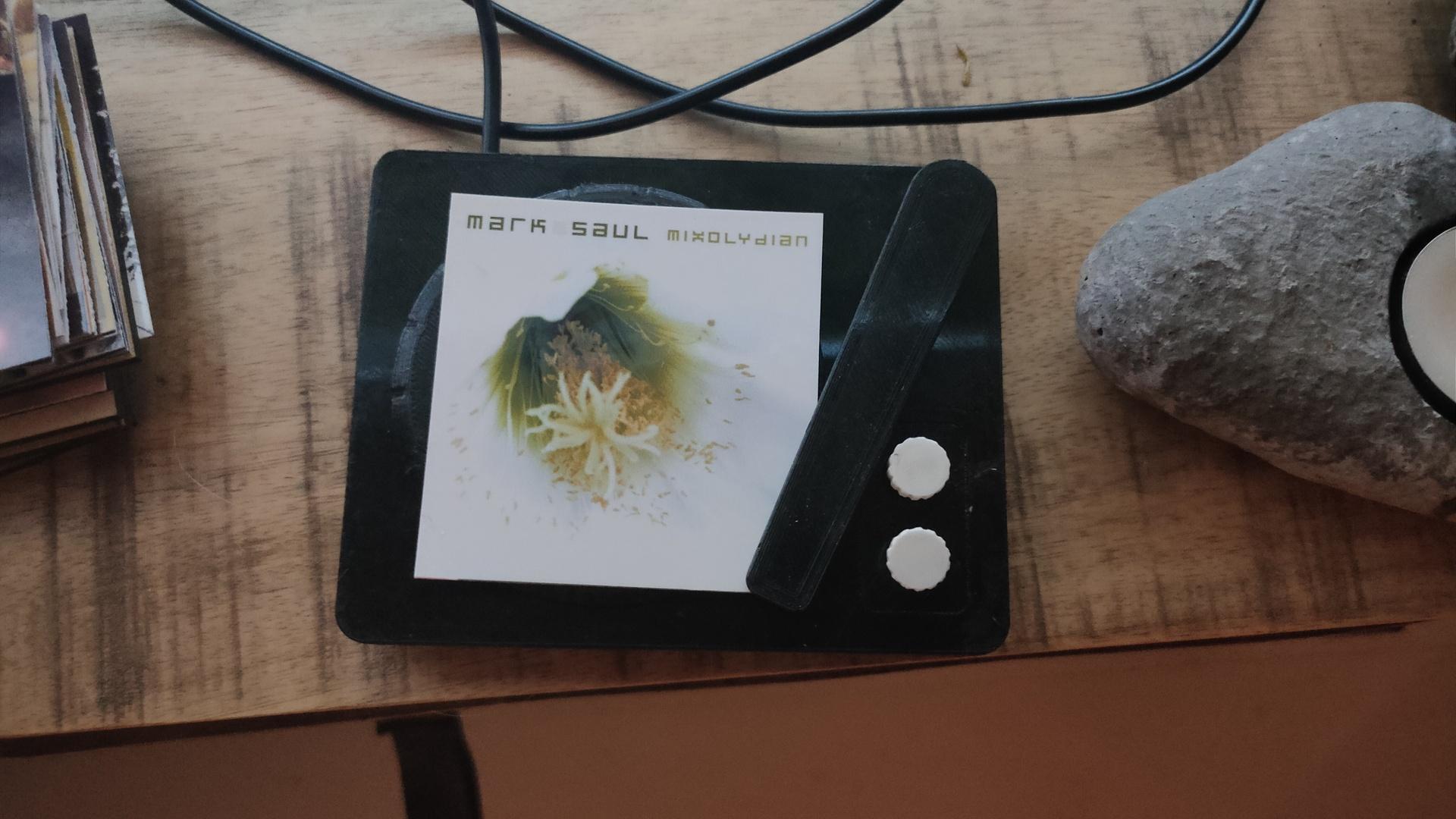
Recordplayer model by kriswillcode, but heavily remixed
Record player is going to be re-printed at a higher quality.
Put a printed image on the player, and it plays the album
Move the arm, and the next track will be played
Press upper white button, and the music will pause/resume
Press lower button … ??? Don’t know yet
Updated python client (see previous posts)
import paho.mqtt.client as mqtt
import urllib.request
from time import sleep

def on_connect(client, userdata, flags, rc):  # The callback for when the client connects to the broker
        print("Connected with result code {0}".format(str(rc)))
        client.subscribe("spotify/rfid/idlms")
        client.subscribe("spotify/rfid/but1")
        client.subscribe("spotify/rfid/but2")
        client.subscribe("spotify/rfid/arm")

def on_message(client, userdata, msg):  # The callback for when a PUBLISH message is received from the server.
        print("Message received-> " + msg.topic + " " + str(msg.payload))  # Print a received msg
        if msg.topic == "spotify/rfid/idlms":
            urllib.request.urlopen("http://LMS-SERVER-IP:9000/anyurl?p0=playlistcontrol&p1=album_id:" + msg.payload.decode() + "&p2=cmd:load&player=00:04:20:16:d9:04")
        if msg.topic == "spotify/rfid/but1":
            urllib.request.urlopen("http://LMS-SERVER-IP:9000/anyurl?p0=pause&player=00:04:20:16:d9:04")
            sleep(1)
        if msg.topic == "spotify/rfid/but2":
            urllib.request.urlopen("http://LMS-SERVER-IP:9000/anyurl?p0=pause&pt=1&player=00:04:20:16:d9:04")
            sleep(1)
        if msg.topic == "spotify/rfid/arm":
            urllib.request.urlopen("http://LMS-SERVER-IP:9000/status.html?p0=button&p1=jump_fwd&player=00:04:20:16:d9:04")
            sleep(1)

client = mqtt.Client("lmsclient")  # Create instance of client with client ID “digi_mqtt_test”
client.on_connect = on_connect  # Define callback function for successful connection
client.on_message = on_message  # Define callback function for receipt of a message
client.connect('MQTTSERVER', 1883)
client.loop_forever()  # Start daemon
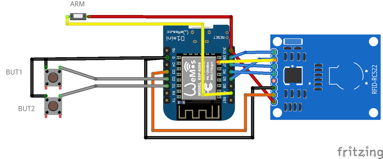
Wemos INO file
#include <Arduino.h>
#include <SPI.h>
#include <MFRC522.h>
#include <ESP8266WiFi.h>
#include <WiFiClient.h>
#include <PubSubClient.h>
#define SS_PIN 15
#define RST_PIN 0

const int buttonPin1 = D1;
const int buttonPin2 = D2;

int buttonState1 = 0;
int buttonState2 = 0;

MFRC522 mfrc522(SS_PIN, RST_PIN);
  MFRC522::StatusCode status; //variable to get card status

  byte buffer[18];  //data transfer buffer (16+2 bytes data+CRC)
  byte size = sizeof(buffer);

  uint8_t pageAddr = 0x06;  //In this example we will write/read 16 bytes (page 6,7,8 and 9).
                            //Ultraligth mem = 16 pages. 4 bytes per page.
                            //Pages 0 to 4 are for special functions.

unsigned long cardId = 0;
WiFiClient net;
PubSubClient client(net);
const char* mqtt_server = "MQTTBROKER";
const char* ssid = "MYSSID";
const char* password = "MYWIFIPASWORD";
String topicStr = "";
byte buffer2[8];

boolean Rflag=false;
int r_len;
char payload[5];
byte value[5];
void setup() {
  Serial.begin(9600);
    pinMode(buttonPin1, INPUT_PULLUP);
    pinMode(buttonPin2, INPUT_PULLUP  );

  SPI.begin();
  mfrc522.PCD_Init();
  WiFi.mode(WIFI_AP_STA);
  WiFi.begin(ssid, password);
  client.setServer(mqtt_server, 1883);
     delay(100);
    client.setCallback(callback);
      delay(100);
    client.subscribe("spotify/rfid/in/#");
}
void reconnect() {
  while (WiFi.waitForConnectResult() != WL_CONNECTED) {
  }
  while (!client.connected()) {
    String clientId = "rfid-";
    clientId += String(random(0xffff), HEX);
    if (!client.connect(clientId.c_str(), "rfidclient", "...")) {
      delay(5000);
    }
  }
  client.subscribe("spotify/rfid/in/#");
}
void callback(char* topic, byte* payload, unsigned int length) {
  Serial.print(F("Called"));
   Rflag=true; //will use in main loop
   r_len=length; //will use in main loop
   int j=0;
     for (j;j<length;j++) {
       buffer2[j]=payload[j];
       //Serial.print((char)payload[j]);
       }
if (r_len < 3) {
  Rflag=false;
  Serial.print(F("Set false"));
}
buffer2[j]='\0'; //terminate string
}

void loop() {
    if (!client.connected()) {
    reconnect();
  }

buttonState1 = digitalRead(buttonPin1);
  //Serial.print(buttonState1);
  if (buttonState1 == 0 ) {
    client.publish("spotify/rfid/but1", "0");
  }
buttonState2 = digitalRead(buttonPin2);
  //Serial.println(buttonState2);
  if (buttonState2 == 0 ) {
    client.publish("spotify/rfid/but2", "0");
  }

int reading = analogRead(0);
  //Serial.println(reading);
  if (reading > 500 ) {
    client.publish("spotify/rfid/arm", "0");
  }

  client.loop();
  if (!mfrc522.PICC_IsNewCardPresent()) {
    return;
  }
  if (!mfrc522.PICC_ReadCardSerial()) {
    return;
  }
if (Rflag) {
        for (int i=0; i < 4; i++) {
    //data is writen in blocks of 4 bytes (4 bytes per page)
    status = (MFRC522::StatusCode) mfrc522.MIFARE_Ultralight_Write(pageAddr+i, &buffer2[i*4], 4);
    if (status != MFRC522::STATUS_OK) {
      return;
    }

  }
  Rflag=false;
}

  cardId = getCardId();
  char buffer3[10];
  sprintf(buffer3, "%lu", cardId);
  client.publish("spotify/rfid/id", buffer3);

  status = (MFRC522::StatusCode) mfrc522.MIFARE_Read(pageAddr, buffer, &size);
  if (status != MFRC522::STATUS_OK) {
    Serial.println(F("MIFARE_Read() failed: (R)"));
    Serial.println(mfrc522.GetStatusCodeName(status));
    return;
  }

  Serial.println(F("Read data: "));
  for (byte i = 0; i < 5; i++) {
    Serial.write(buffer[i]);
       buffer2[i]=buffer[i];
    }

  client.publish("spotify/rfid/idlms", buffer,5);
  delay(1000);
  mfrc522.PICC_HaltA();
}

unsigned long getCardId() {
  byte readCard[4];
  for (int i = 0; i < 4; i++) {
    readCard[i] = mfrc522.uid.uidByte[i];
  }
  return (unsigned long)readCard[0] << 24
    | (unsigned long)readCard[1] << 16
    | (unsigned long)readCard[2] << 8
    | (unsigned long)readCard[3];
}
"If something is worth doing, it's worth overdoing."