Busy day: I’ve airbrushed some 3D pieces a few days ago, but i need 50 or so more. Meanwhile is was reinstalling octoprint, and making a new version of my Bluetooth page flipper. (Android Music Sheet Pedal Thingy. Which i also didn’t post apparently) But the main project was this:
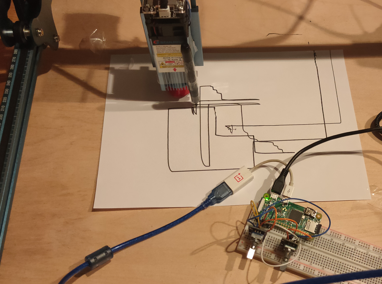
I was curious how fast the stepper motors are on my laser cutter. And for what can we utilize this!
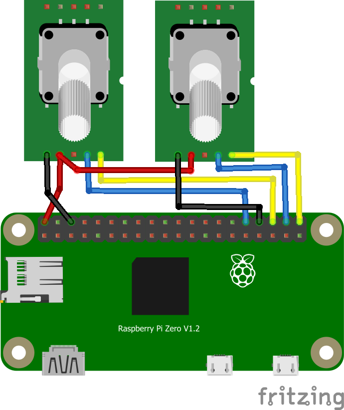
So I took a Raspberry Zero and some rotary encoders, lets make an etch-a-sketch like thingy.
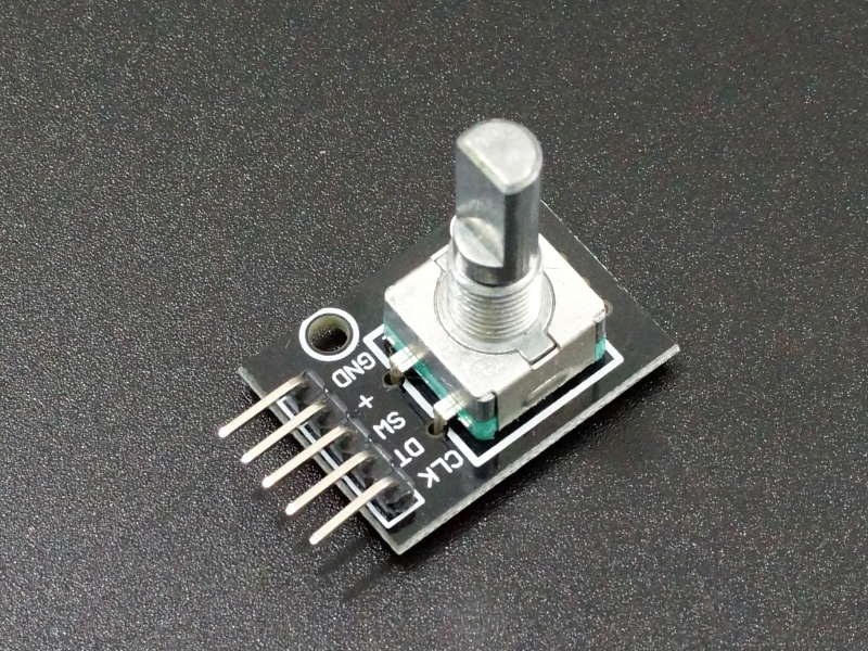
Some rotary encoder modules I had.
Next to do: 3D print a pen holder, and alter the code to enable the laser when moving!
CODE
Below code uses a simple rotary class, and generates control GCodes for the steppers/Sculpfun
import time
import serial
import RPi.GPIO as GPIO
from encoder import Encoder

def valueChanged(value, direction):
    print("* New value: {}, Direction: {}".format(value, direction))

GPIO.setmode(GPIO.BCM)

e1 = Encoder(20, 21, valueChanged)
e2 = Encoder(16, 12, valueChanged)

x = 0
y = 0
arduino = serial.Serial('/dev/ttyUSB0', 115200, timeout=.1)

newx = 0
mystringx = ""
newy = 0
mystringy = ""

arduino.write(str.encode("G00 G17 G40 G21 G54\r\n"))
arduino.write(str.encode('G90\r\n'))
arduino.write(str.encode('M4\r\n'))
arduino.write(str.encode('M8\r\n'))
arduino.write(str.encode('G0 X41.5Y36.05\r\n'))
arduino.write(str.encode('M3\r\n'))
#arduino.write(str.encode('G91\r\n'))
arduino.write(str.encode('G1 X2.5F6000S0\r\n'))
arduino.write(str.encode('G1 X0\r\n'))
arduino.write(str.encode('G1 Y0\r\n'))

try:
    while True:
        data = arduino.readline()[:-2] #the last bit gets rid of the new-line chars
        if data:
                print (data)
        arduino.write(str.encode("G1 F10000\r\n"))
        newx=e1.getValue() *5 + 100
        newy=e2.getValue() *5 + 100
        mystringx=f"G1 X{newx}\r\n"
        mystringy=f"G1 Y{newy}\r\n"
#        print(mystringx)
        arduino.write(str.encode(mystringx))
        arduino.write(str.encode(mystringy))

except Exception:
    pass

GPIO.cleanup()
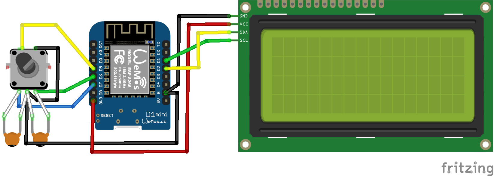
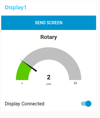
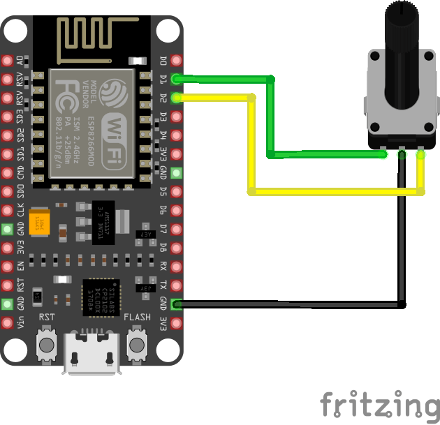
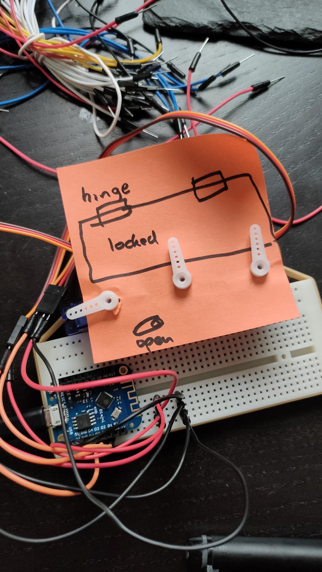
Rotary values are displayed, a push on the rotary sends the value to Mosquitto
Schematic : capacitors are 100nF and display has an I2C backpack
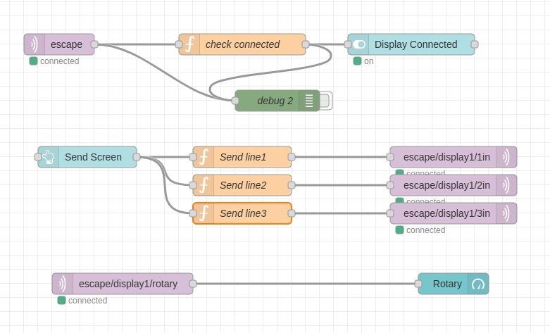
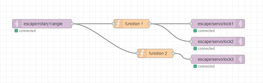
Node-red flow example
Node red GUI
Code :
Notes: There is a problem with 4 line LCD using LiquidCrystal_I2C Lines 3 and 4 will be shifted 4 characters to the right. Workaround is: lcd.setCursor(-4, 2); // Go to column 0, row 3
#include <ESP8266WiFi.h>
#include <PubSubClient.h>
#include <WiFiClient.h>
#include "SoftwareSerial.h"
#include <Ethernet.h>
#include <Arduino.h>
#include <RotaryEncoder.h>
#define wifi_ssid "MYSSID"
#define wifi_password "MYSSIDPASS"
#define mqtt_server "MQTTSERVER"
#define mqtt_port 1883

WiFiClient espClient;
EthernetClient ethClient;

PubSubClient mqtt(espClient);

#include <Wire.h>                  // Include Wire library (required for I2C devices)
#include <LiquidCrystal_I2C.h>     // Include LiquidCrystal_I2C library

LiquidCrystal_I2C lcd(0x27, 16, 4);  // Configure LiquidCrystal_I2C library with 0x27 address, 16 columns and 4 rows
volatile bool flag = false;


#define PIN_IN1 D7
#define PIN_IN2 D6
#define push D5
int temp = 0;

RotaryEncoder *encoder = nullptr;

#if defined(ARDUINO_AVR_UNO) || defined(ARDUINO_AVR_NANO_EVERY)
// This interrupt routine will be called on any change of one of the input signals
void checkPosition()
{
  encoder->tick(); // just call tick() to check the state.
}

#elif defined(ESP8266)
/**
 * @brief The interrupt service routine will be called on any change of one of the input signals.
 */
IRAM_ATTR void checkPosition()
{
  encoder->tick(); // just call tick() to check the state.
}

#endif

void scrollText(int row, String message, int delayTime, int lcdColumns) {
  for (int i=0; i < lcdColumns; i++) {
    message = " " + message;
  }
  message = message + " ";
  for (int pos = 0; pos < message.length(); pos++) {
    lcd.setCursor(0, row);
    lcd.print(message.substring(pos, pos + lcdColumns));
    delay(delayTime);
  }
}

void setup_wifi() {
  delay(10);
  WiFi.mode(WIFI_STA);
  WiFi.begin(wifi_ssid, wifi_password);
  while (WiFi.status() != WL_CONNECTED) {
    delay(500);
  }
}

void setup() {
    setup_wifi();
  mqtt.setServer(mqtt_server, mqtt_port);
  mqtt.setCallback(callback);
  Serial.begin(115200);
  Serial.println("initializing...");

  WiFiClient espClient;
PubSubClient mqtt(espClient);

 mqtt.setClient(espClient);
  mqtt.setServer(mqtt_server, 1883);

mqtt.setCallback(callback);
   mqtt.subscribe("escape/display1/#");

  lcd.init();                        // Initialize I2C LCD module
  lcd.backlight();                   // Turn backlight ON

  lcd.setCursor(0, 0);               // Go to column 0, row 0
  lcd.print("Init");
  lcd.setCursor(0, 1);               // Go to column 0, row 1
  lcd.print("Display #1");

  encoder = new RotaryEncoder(PIN_IN1, PIN_IN2, RotaryEncoder::LatchMode::TWO03);

  // register interrupt routine
  attachInterrupt(digitalPinToInterrupt(PIN_IN1), checkPosition, CHANGE);
  attachInterrupt(digitalPinToInterrupt(PIN_IN2), checkPosition, CHANGE);

 pinMode(push, INPUT_PULLUP);
}

void reconnect() {
  // Loop until we're reconnected
  while (!mqtt.connected()) {
    // Create a random client ID
    String clientId = "ESP8266Client-";
    clientId += String(random(0xffff), HEX);
    // Attempt to connect
    if (mqtt.connect(clientId.c_str())) {
      // Once connected, publish an announcement...
      mqtt.publish("escape", "display1 connected");
      // ... and resubscribe
      mqtt.subscribe("escape/display1/#");
    } else {
      // Wait 5 seconds before retrying
      delay(5000);
    }
  }
}

void callback(char* topic, byte* payload, unsigned int length) {

payload[length]= '\0';
char * charPointer = (char *)payload;
String s="";
s =charPointer;
s = s + "               ";
    String topicStr = topic;

if (topicStr == "escape/display1/clear"){
   lcd.clear();
}
if (topicStr == "escape/display1/1in"){
  lcd.setCursor(0, 0);               // Go to column 0, row 1
  lcd.print(s.substring(0, 16));
}
if (topicStr == "escape/display1/2in"){
  lcd.setCursor(0, 1);               // Go to column 0, row 2
  lcd.print(s.substring(0, 16));
}
if (topicStr == "escape/display1/3in"){
  lcd.setCursor(-4, 2);               // Go to column 0, row 3
  lcd.print(s.substring(0, 16));
}
if (topicStr == "escape/display1/4in"){
  lcd.setCursor(-4, 3);               // Go to column 0, row 4
  lcd.print(s.substring(0, 16));
}
    }

void loop() {
   if (!mqtt.connected()) {
    reconnect();
  }
    mqtt.loop();

  static int pos = 0;

  encoder->tick(); // just call tick() to check the state.

  int newPos = encoder->getPosition() / 2;
    if (pos != newPos) {
    String nr="";
    Serial.print("pos:");
    Serial.print(newPos);
    Serial.print(" dir:");
    Serial.println((int)(encoder->getDirection()));
    pos = newPos;
 // hier nog iets mee doen
   // zonder setPos moet je eerst lang clockwise voordat weer gaat tellen
    // met setPos blijft 0
   // if (pos < 0){
    //  pos = 0;
   //     encoder->setPosition(0);
   // }

    nr = pos + "        ";
    lcd.setCursor(10, 3);               // Go to column 10, row 3
  lcd.print(pos);
  lcd.print("   ");
  }

  temp = digitalRead(push);
  if (temp == LOW) {

char msg_out[20];
sprintf(msg_out, "%d",pos);
        mqtt.publish("escape/display1/rotary", msg_out);
  }

}
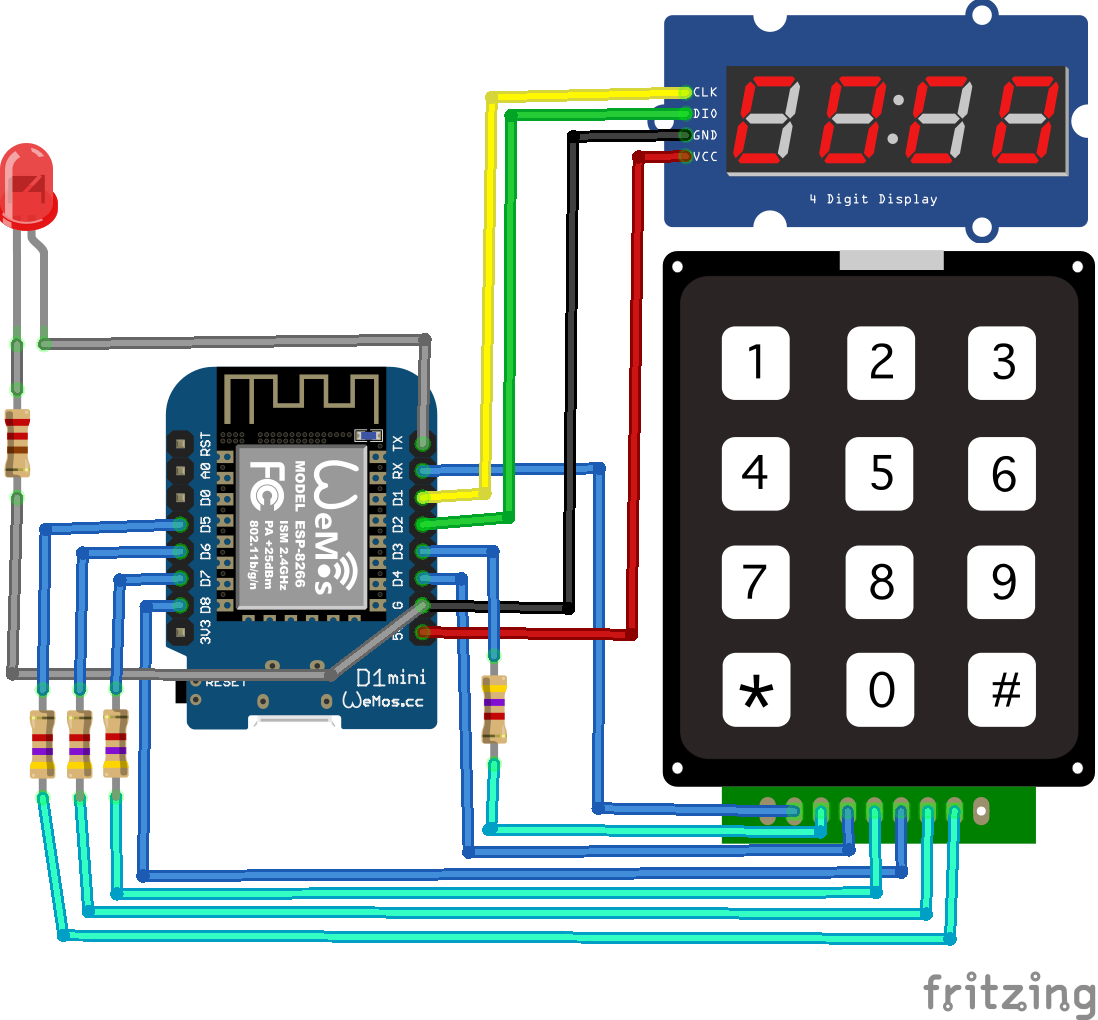
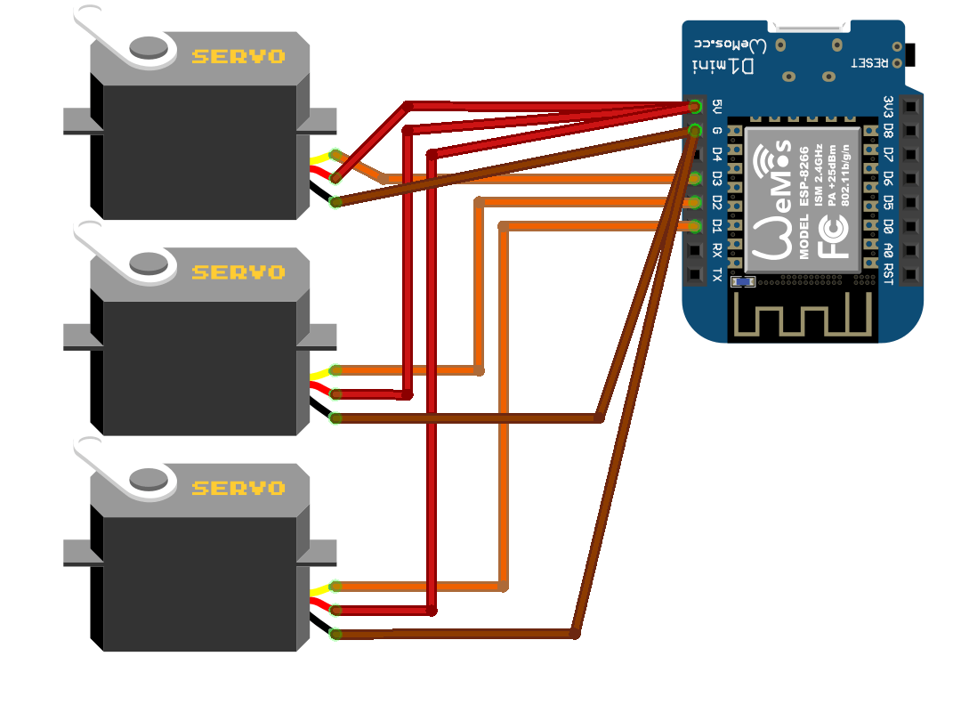
I was needing ALL GPIO pins, even RX/TX ( see trick below) When doing so, you can’t use serialprint. Do NOT enable, your sketch won’t work!
Don’t use pullup on D8, you can’t upload to the wemos if you do that
Due to library conflicts in keypad.h, DON’T change the order in the source. You will end up with compile errors!
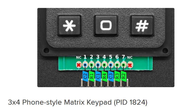
The keypad has a weird pinout, but there are similar keypads with alternative layouts. Measure this using a multimeter.
The pull-up resistors will help fighting ghost key presses!
I2C needs D1/D2
To use RX/TX as GPIO pins you need to do the following:
//Define pins
  int led = 1; //tx
  int col = 3; //rx

// Change to function mode 3
// see https://www.esp8266.com/wiki/doku.php?id=esp8266_gpio_pin_allocations
  pinMode(1, FUNCTION_3);
  pinMode(3, FUNCTION_3);

// Revert to normal mode
// pinMode(1, FUNCTION0);

// Define mode input/output
// i'm using led to control the led so thats an output
// I'm using col for the keypad column scanner, that's an input
  pinMode(led, OUTPUT);
  pinMode(col, INPUT);
Complete code
The (*) clears input The (#) sends the pin code using MQTT
Sending a 0 or 1 to escape/keypadin topic will toggle the led
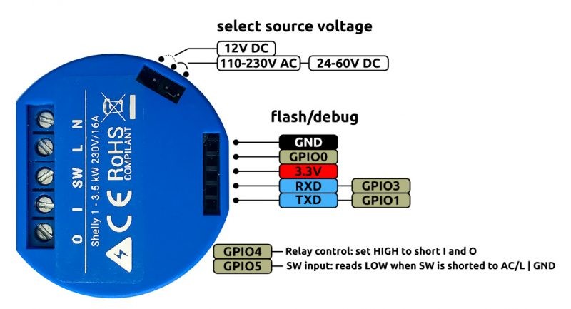
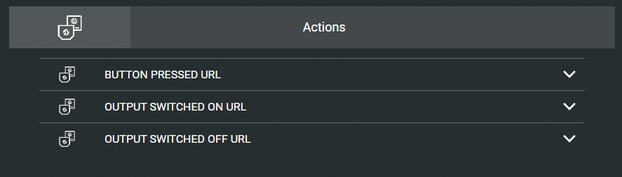
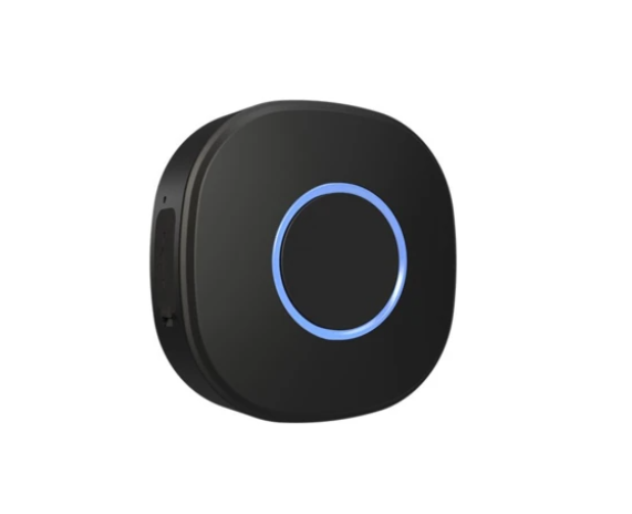
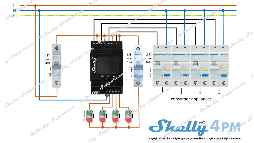
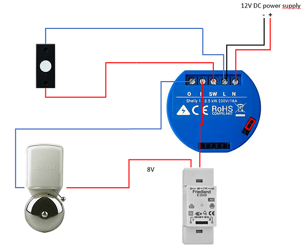
I love shellies, easy to implement and hacker friendly.
MQTT out of the box. Curl in and out – you can switch it on/off using curl, but it can send a http command also. I’ve used this with Domoticz and Home Assistant. It has a webinterface, with timers, and there is also a client for Android/Iphone You’ve got some own gpio pins to your disposal and the unit is flash-able!
curl -X POST https://shellydevice/device/relay/control -d "channel=IDHERE&turn=on&id=ID&auth_key=AUTH"
The device is not isolated from the mains. To flash it, the mains must be disconnected.
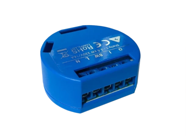
SHELLY 1
I use this for simple on/off switches around the house. Using it with a physical switch and MQTT (Nodered)
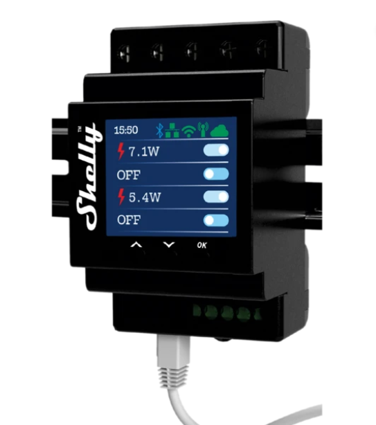
Same as above but this one has a build in power meter
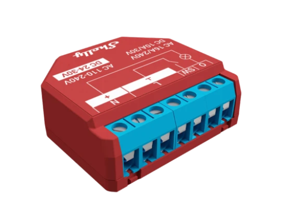
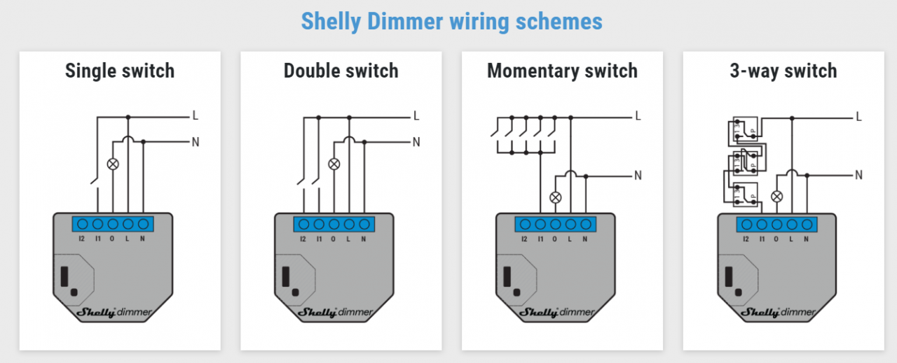
SHELLY DIMMER
Generic dimmer
Dimmer with low voltage rotary encoder! https://www.instructables.com/Shelly-Dimmer-Wall-Switch-With-Rotary-Knob-and-Hom/
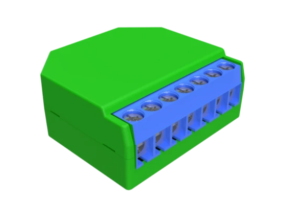
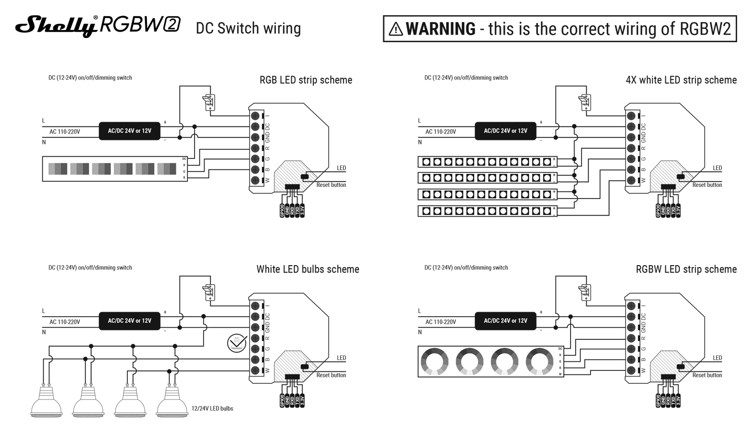
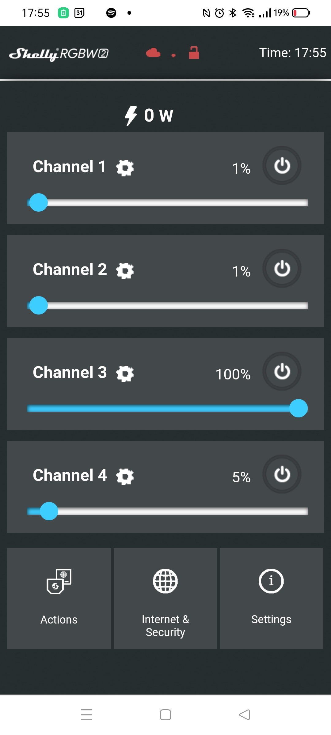
SHELLY RGBW2
A RGBW / 4 Channel controller You can connect RGB strips, but also dimmable white strips in 4 channels. 12V or 24V. NOTE! : There is a common 12V connection, and GND will be controlled!
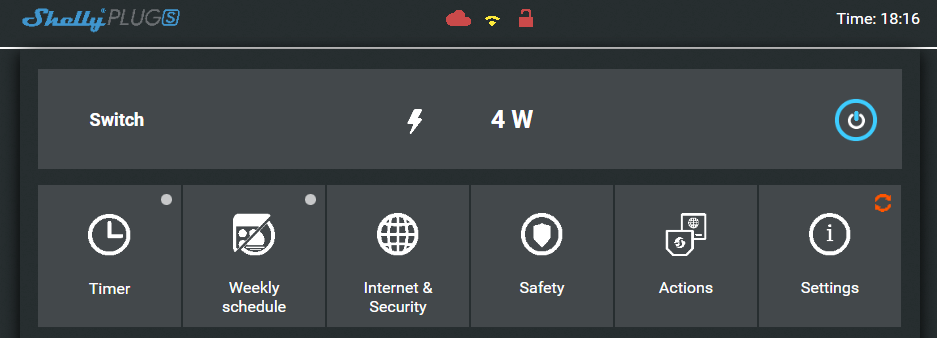
SHELLY PLUG S
I love these small wall plugs, i’ve used these also to find power consuming devices around the house.
For example, i made a nodered flow, to see if the washing machines are running or not.
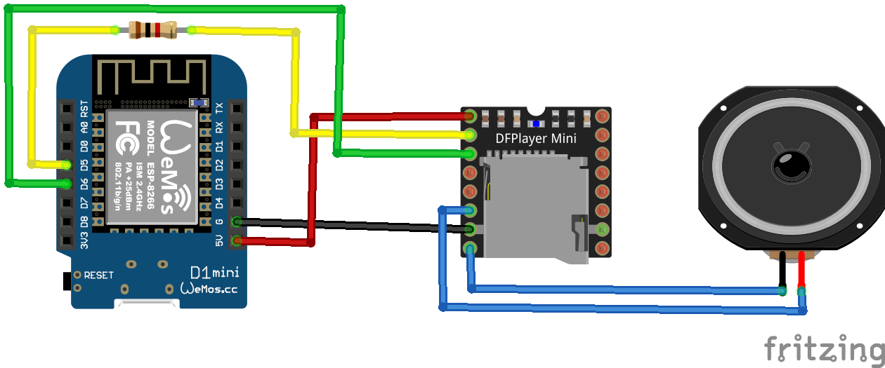
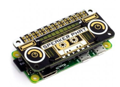
I’ve got an old Speaker Phat, and a Raspberry Zero
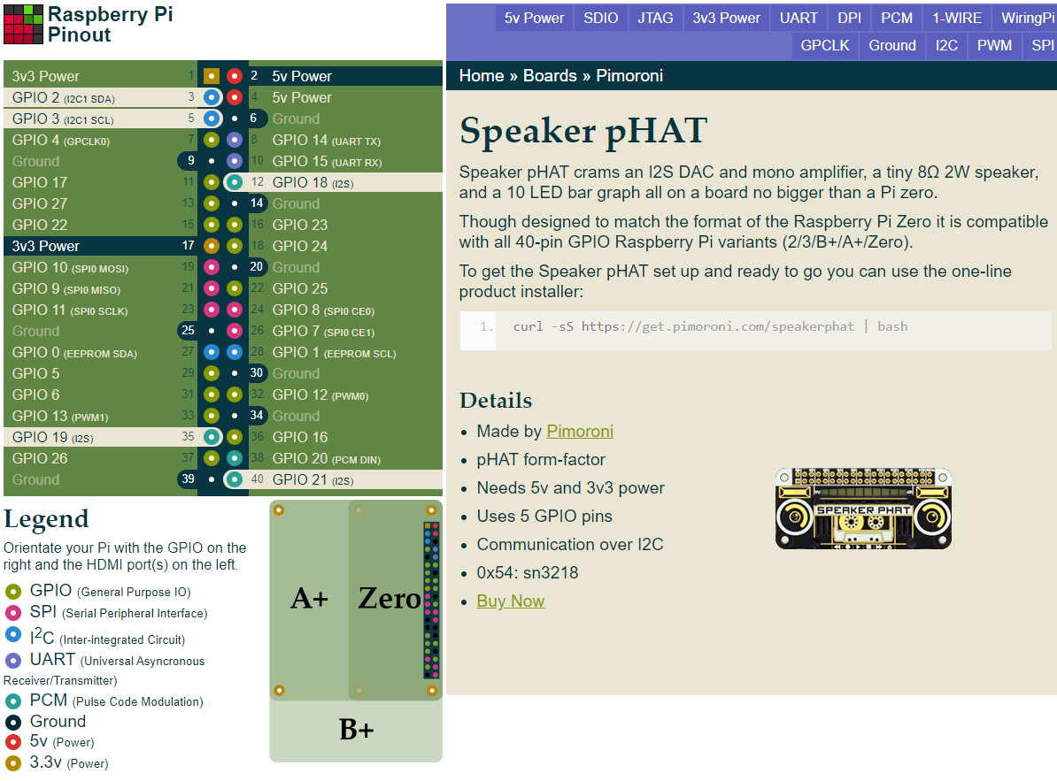
An audio add-on board for Raspberry ( same size as the Zero )
Connections
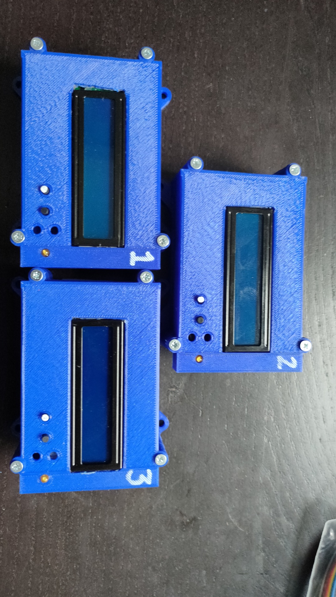
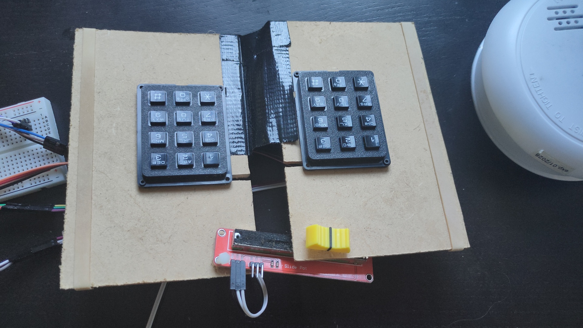
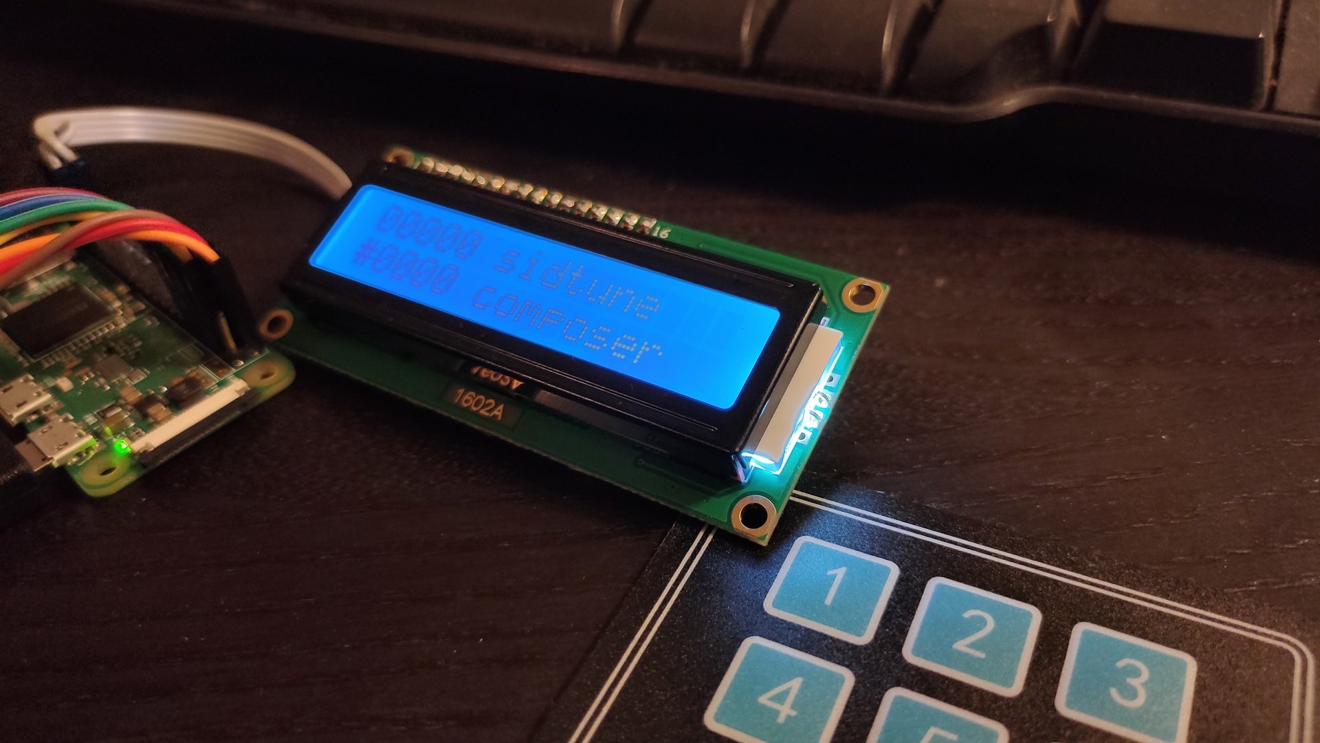
My initial idea was to have the “High Voltage Sid Collection” (Downloaded the 55000 pack) On a mini device, battery operated and with a little keypad.
On the keypad i can select the Sidtune to play, or pressing A and a number the Sids from a certain artist.
The display gives you information about the tune being played. ( The display has an I2C hat to convert 8bits to I2C )
See pinout phat above. I’ve got three choices for I2C connection (green/blue to the Phat)
Direct connect and use different addresses
Use a I2C hub and different addresses
Define a secondary I2C on the raspberry
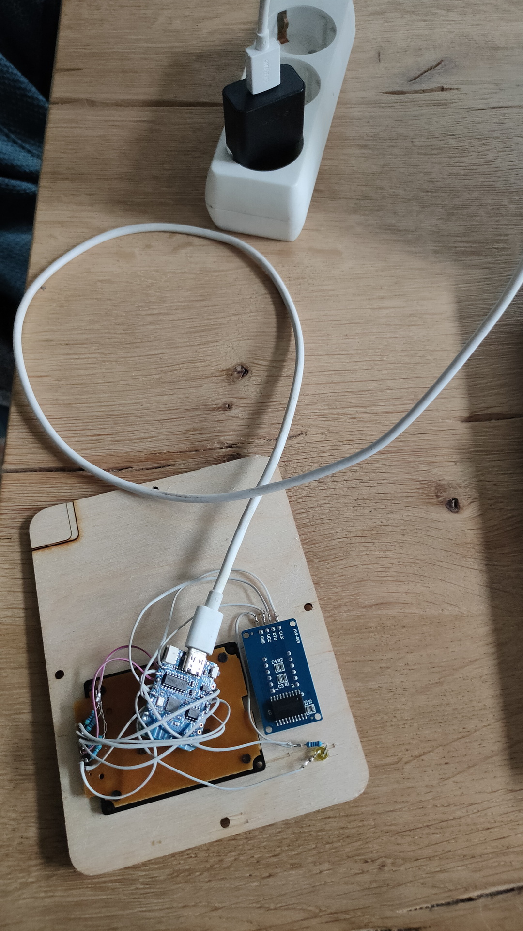
So I made the first test setup …
Underrun occurred .. So back to the drawingboard. I probably need a better Audio Hat. First to try .. Zero fast enough for sidplay2? Maybe audio over hdmi works??
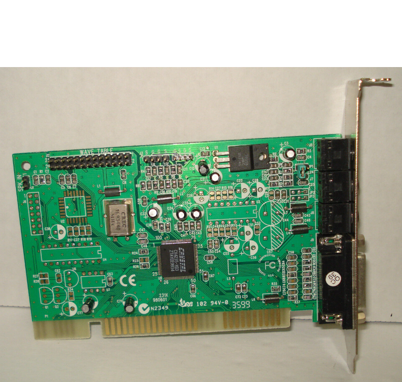
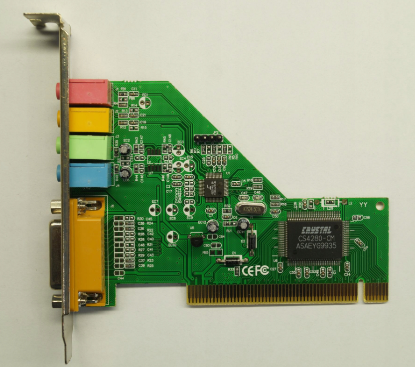
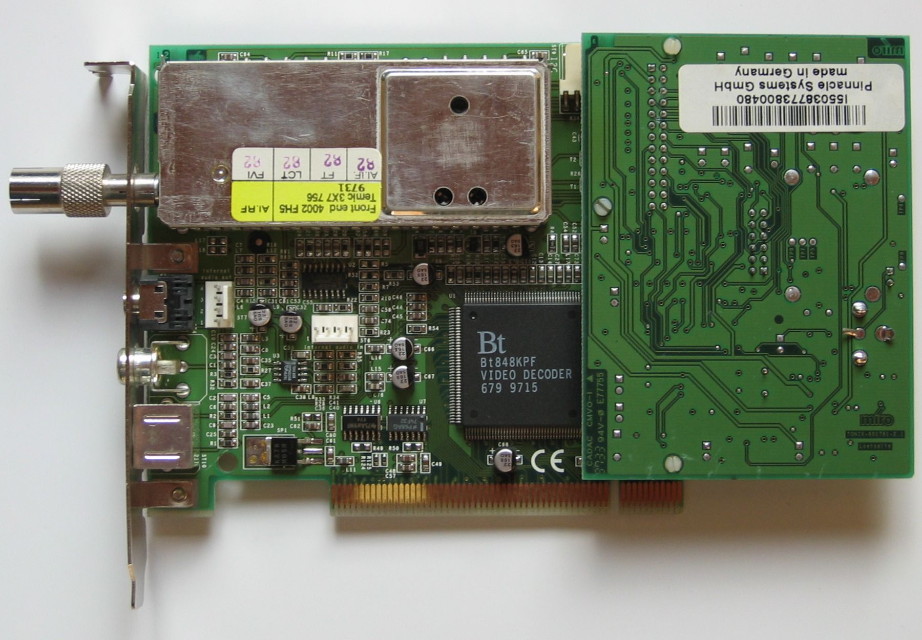
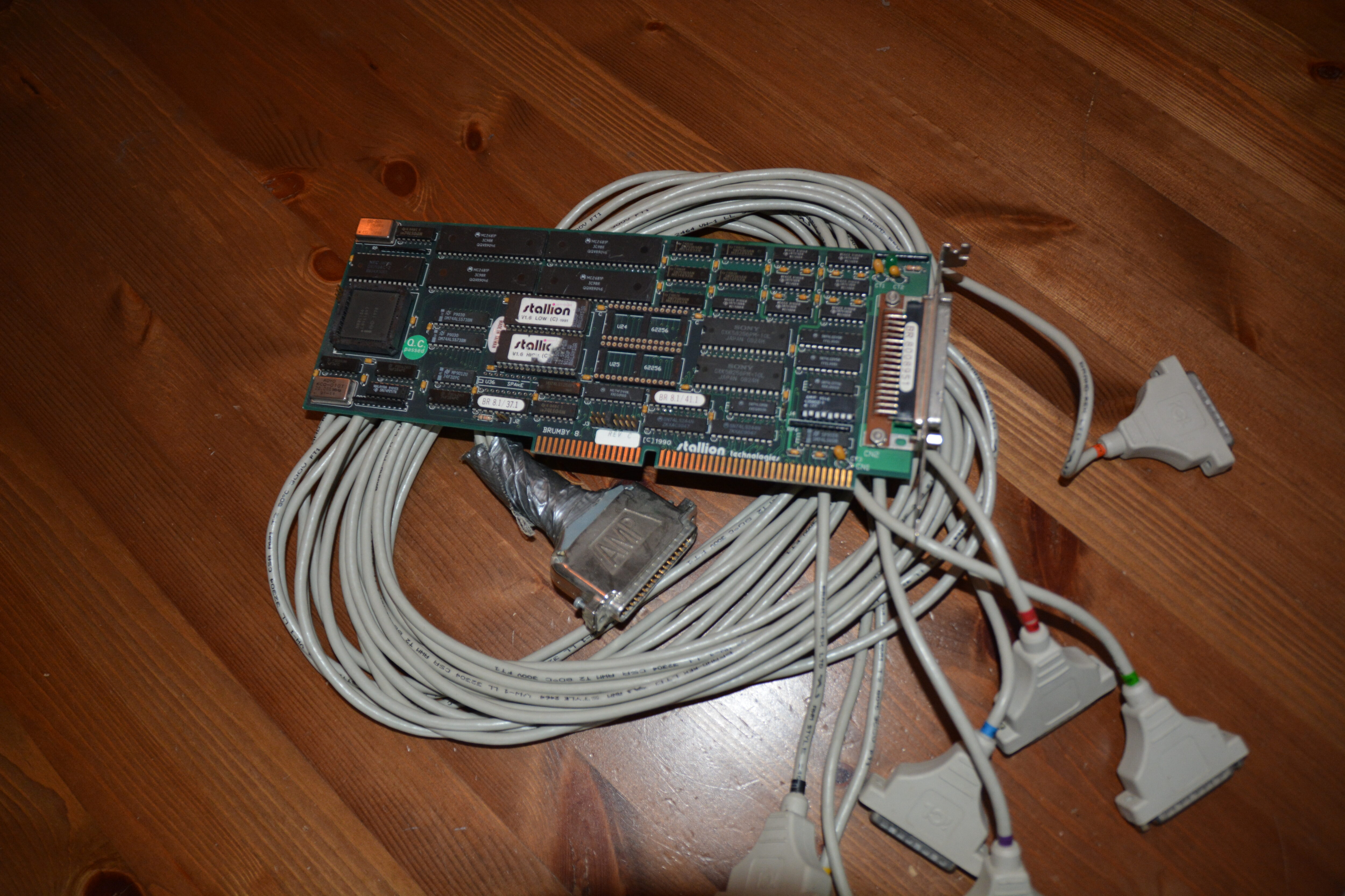
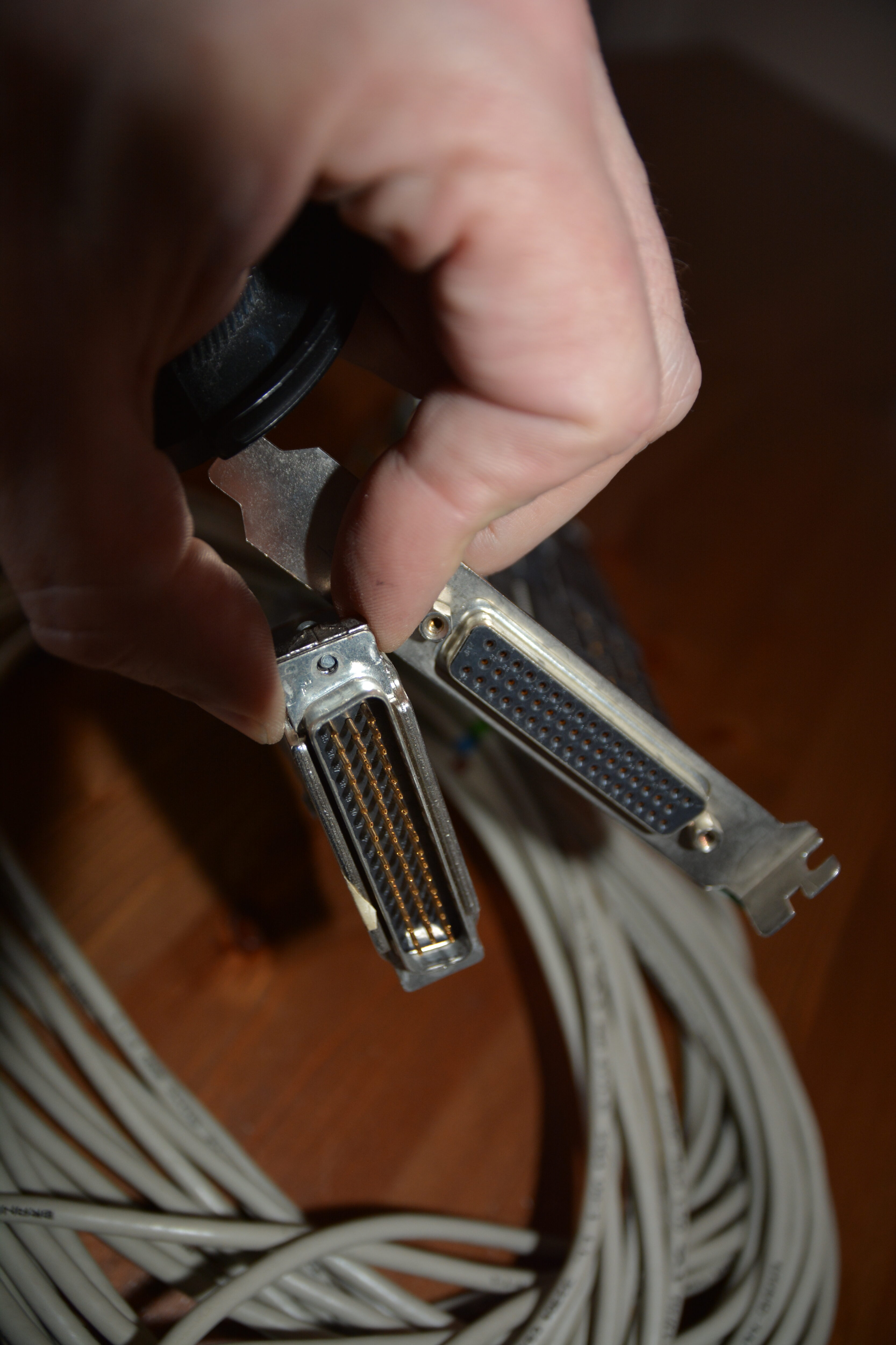
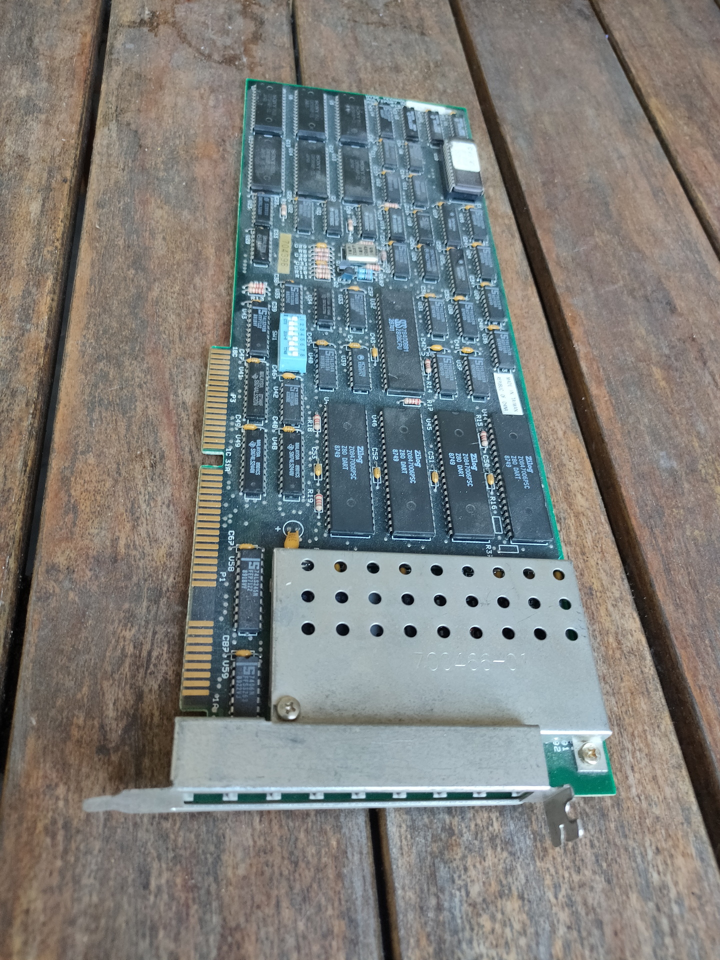
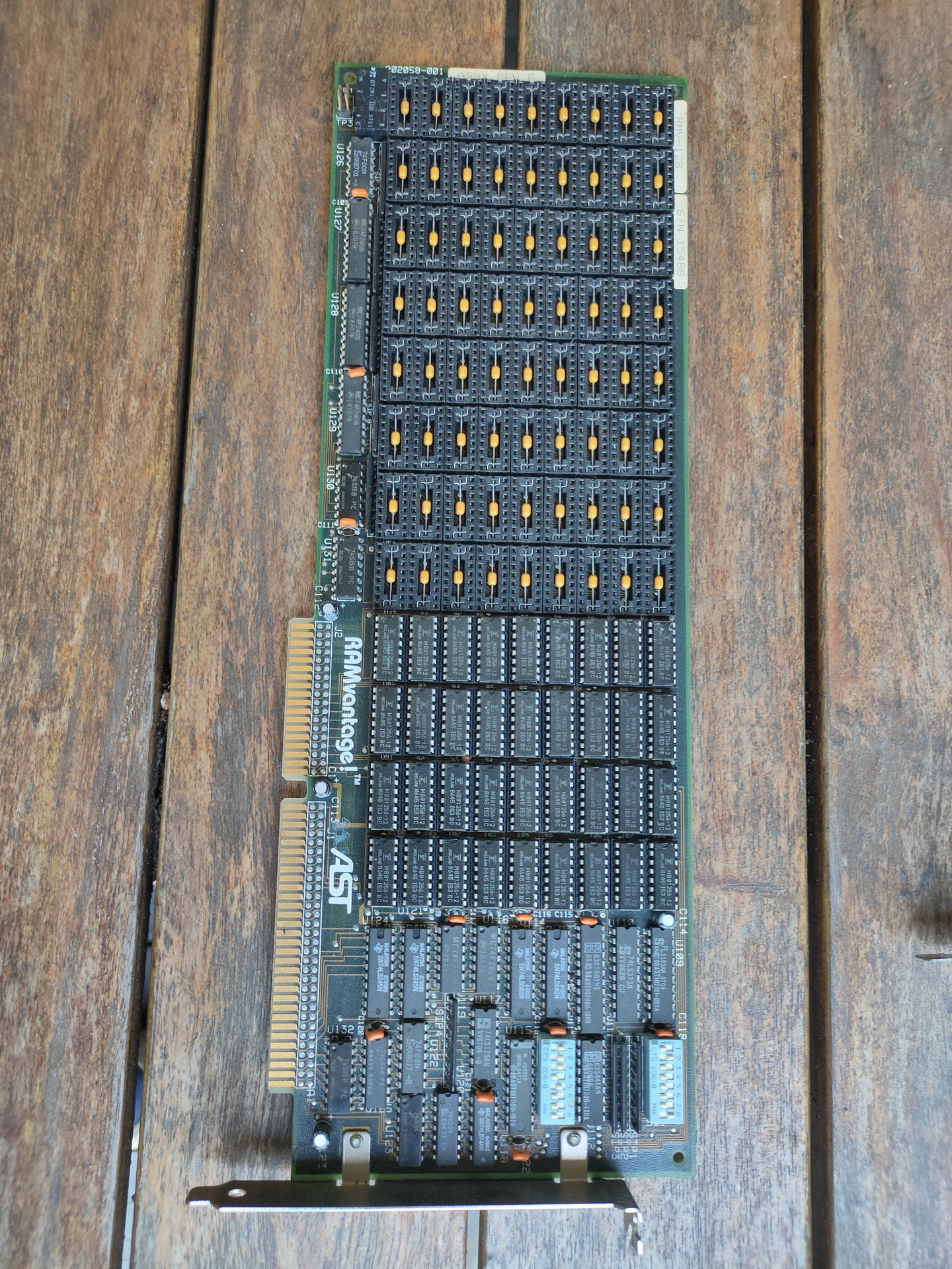
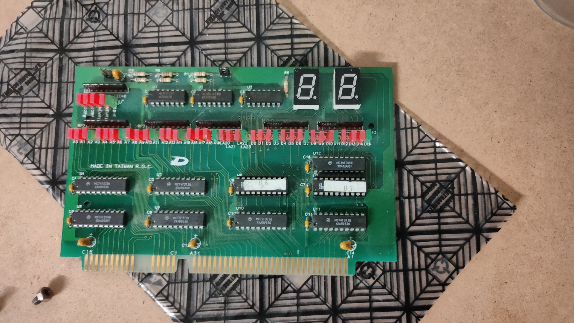
Only cards worth mentioning. I will add more information to this page
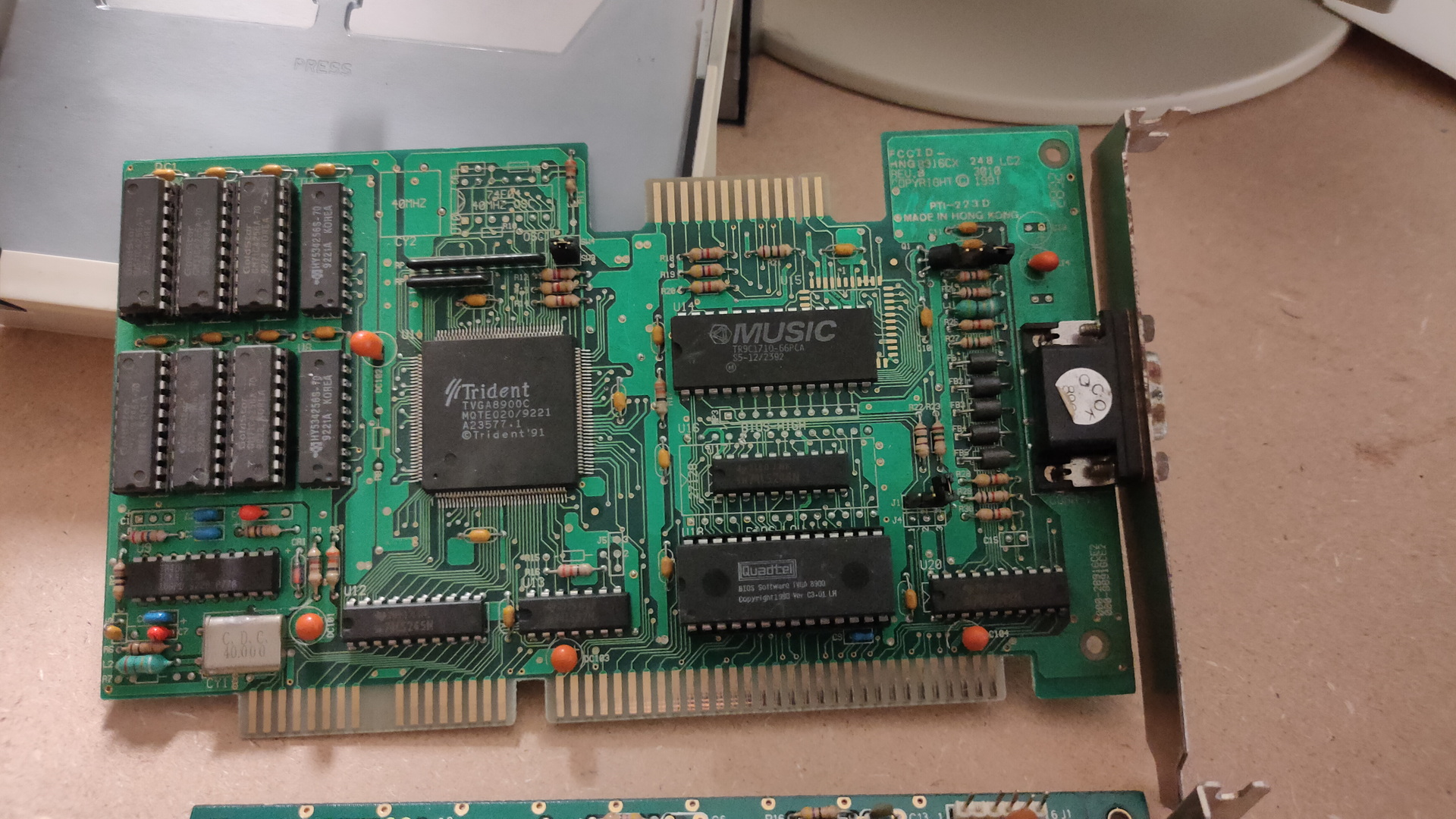
Graphics:
Hercules ???? – Did a lot of machinecode on this one. (Which?) CGA/EGA Card ??? – Machinecode hacking VGA .. first card also machine code hacking Matrox Some cards i knew a lot about, i did some manipulations using assembly that were very interesting, but only worked on that specific brand.
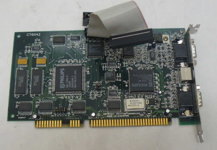
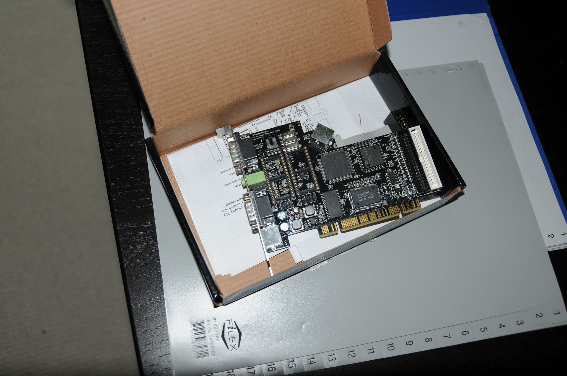
The Catweasel is a family of enhanced floppy-disk controllers from German company Individual Computers. These controllers are designed to allow more recent computers, such as PCs, to access a wide variety of older or non-native disk formats using standard floppy drives.
You could connect joysticks and there is a socket for a SID chip on the card.