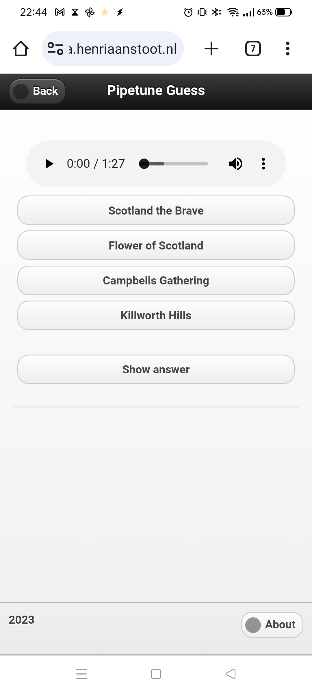
While watching a online python course, I was writing the code for a music guessing game (Highland Bagpipe Tunes) The core is working, now it’s a matter of filling this “pruts” with tunes.
Switching between python, php, bash and C is a nightmare 🙂
A screenshot of work in progress
Then the postman came .. with goodies. I needed the MAX9814 analog microphone with amplifier, all of my other sensors were not up to the task.
So I switched to this WIP with the MAX9814. I want to make a little gadget using an Arduino and 9 leds, which uses FFT to blink which note I am playing on my Highland Pipes.
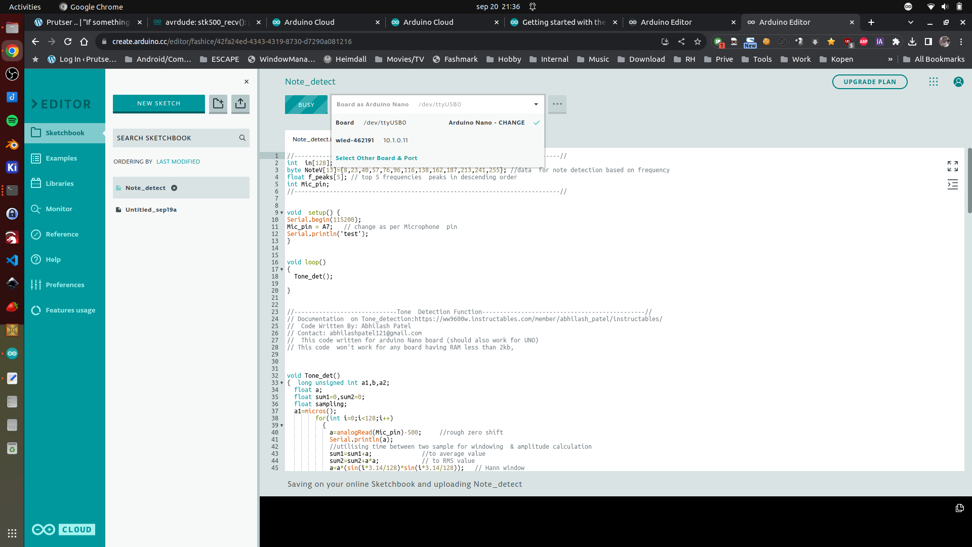
So detecting is working, now I have to attach a bunch of leds.
First test using Arduino Cloud (I still prefer PlatformIO) But this is better than the old IDE. (Note, you have to install an agent to connect your browser to a board)
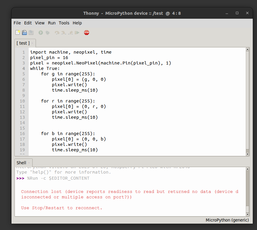
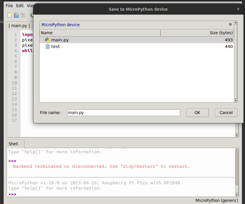
Next thing I did today: Getting my waveshare RP-2040 Zero working with micropython.
Great the little NeoPixel Led on the board.
Steps to get this working:
Install Thonny
Connect the rp2040 via USB with the boot button pressed
place RPI_pico.xxxx.uf2 on the mounted usb disk, it will reboot
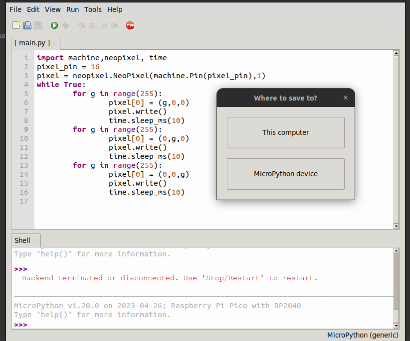
Run Thonny connect and run a test program
Want to run program @boot ? save -> to device, and call main.py
I’m still having problems getting a working floppy drive in my machine. (Broken FDD card, drive errors etc)
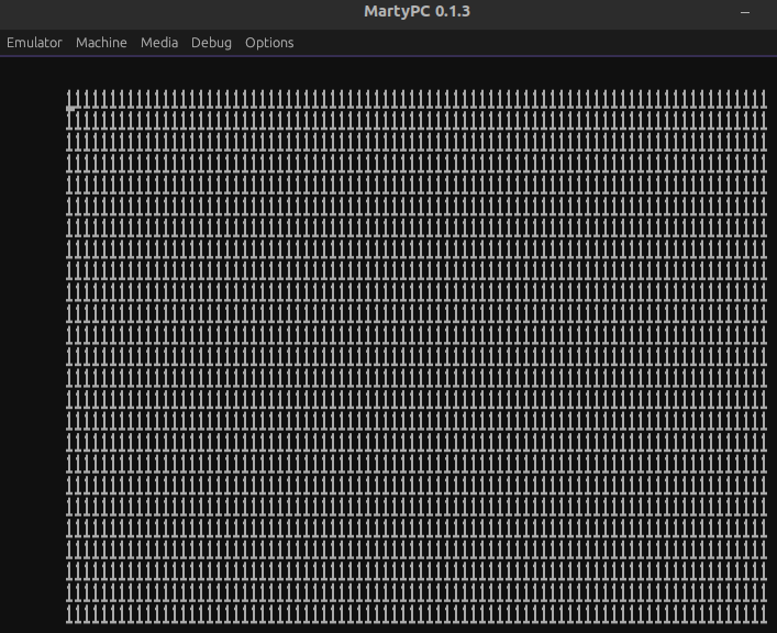
The raster bar (also referred to as rasterbar or copperbar) is an effect used in demos and older video games that displays animated bars of colour, usually horizontal, which additionally might extend into the border, a.k.a. the otherwise unalterable area (assuming no overscan) of the display
When you look at the left side of the screen you see the color bar in the border (outside the normal pixel screen)
I first tried to get it working in DosBOX, but thats a mess. Good for simple emulation but not hardcore register manipulation.
Below dosbox
Three examples below are in PCem
Not waiting for vsync, gives some idea how much timing is left when doing barsOther effect addedEffect as on the real hardware except emulated using PCeM
use16
org 0x100

CRTC_INDEX = 0x03D4
CRTC_DATA = 0x03D5
INPUT_STATUS = 0x03DA
MAXIMUM_SCAN_LINE = 0x09
LINE_OFFSET = 0x13

jmp start

updown DB 30
direction DB 0
filename DB "shoes.bmp",0

start:
; set mode 320x200 256 colors palette
        mov ah,0x0
        mov al,13h
        int 10h

; clear screen routine, not really needed
clearscreen:
        push ax
        mov ax, 0a000h
        mov es, ax
        pop ax
        xor di, di
        inc ax
        mov cx, 64000 ; 320x200
        rep stosb

; call file loader
        call Loadfile

        push cs
        pop ds

; after displaying the image or displaying an error, wait for keypress to exit
waitforkeyloop:
        call effect     ; Calling the effect
        MOV AH,1
        INT 16h
        JZ waitforkeyloop
        XOR AH,AH
        INT 16h
Exit:
        MOV AX,3        ; default text mode 3
        INT 10h
        MOV AX,4C00h    ; exit to dos (terminate process)
        INT 21h

Loadfile:
        MOV DX,filename
        MOV AX,3D00h    ; open filehandle
        INT 21h
        JC Err1
        MOV BX,AX       ; filehandle
        MOV CX,0FFFFh   ; size
        mov dx,0a000h   ; destination 0000:a000h - Screen memory
        mov ds,dx

        MOV DX,0
        MOV AH,3Fh      ; read from file
        INT 21h
        JC  Err1
        MOV AH,3Eh      ; close filehandle
        INT 21h

        RET
; print error
Err1:
        push cs         ; make ds same as cs
        pop ds
        MOV DX,TxtErr1  ; error
        MOV AH,09h
        INT 21h
        RET

effect:
        cli             ; stop interrupts
        call waitvretrace       ; wait for vertical retrace
        mov al, 0    ; set color index 0 to black (needs to be converted to a function
        mov dx, 3c8h
        out dx, al
        inc dx       ; now 3c9h
        mov al, 0h
        out dx, al   ; set R = 0
        mov al, 0h
        out dx, al   ; set G = 0
        mov al, 0h
        out dx, al   ; set B = 0

; gets start scanline and direction
        mov al,[updown]
        mov ah,[direction]
        cmp ah,0
        jz      addcounter
        dec al
        cmp al,30
        jnz gohere
        mov ah,0
        mov [direction],ah
        jmp gohere
addcounter:
        inc al
        cmp al,100
        jnz gohere
        mov ah,1
        mov [direction],ah
gohere:
        mov [updown],al

; al = scanline, call wait for scanline
        call waithretrace
        mov al, 0    ; set color index 0 to blueish
        mov dx, 3c8h
        out dx, al
        inc dx
        mov al, 11h
        out dx, al
        mov al, 22h
        out dx, al
        mov al, 33h
        out dx, al
; wait 10 scanlines (height of bar)
        mov al,10
        call waithretrace

; draw black again
        mov al, 0    ; set color index 0's rgb value
        mov dx, 3c8h
        out dx, al
        inc dx       ; now 3c9h
        mov al, 0
        out dx, al   ; set R = 11h
        mov al, 0h
        out dx, al   ; set G = 22h
        mov al, 0h
        out dx, al   ; set B = 33h

        sti     ; start interrupts again
        ret

; this waits for vertical retrace
waitvretrace:
        mov dx,INPUT_STATUS
waitv1:
        in al,dx
        test al,8
        jnz waitv1
waitv2:
        in al,dx
        test al,8
        jz waitv2
        ret

; routine that waits for horizontal retrace
waithretrace:
        mov cl,al
        mov dx,INPUT_STATUS
waith1:
        in al,dx
        test al,1
        jnz waith1
waith2:
        in al,dx
        test al,1
        jz waith2
        dec cl
        cmp cl,0
        jnz waith1
        ret

TxtErr1 DB "shoes.bmp not found!",7,10,13,"$"
I’ve got a Wifi outside of my network for guest and emergency. ( 2 SSIDs)
Then a main Wifi router in my livingroom, one in my workshop/studio and one in the Attic (Electronics Lab)
So three main Wifi AccessPoints. These all have the same SSID’s but on different frequencies. That way i’ve got roaming in and outside my house. Also some virtual accesspoints are configured. I’ve got a main, folkband, IOT, guest-inside all on 2.4Ghz and 5Ghz.
I watched a lot of YT presentations about Mikrotik Wifi.
So I ended up with DFS safe channels 20Mhz for 2.4 and 20/40Mhz Ce for 5Ghz. (subchannels for each after some frequency scanning) (2.4 does a failback to 20Mhz whenever there is even one client detected which connects only on this band. Such as some old IOT stuff) 2.4 in only 1,6 and 11 no overlap, each on another device. 300Mbps is sufficient for my wifi 🙂
I’ve got accesslists in place and i’m going to read into kicking a client when the signal strenght is below -50dB
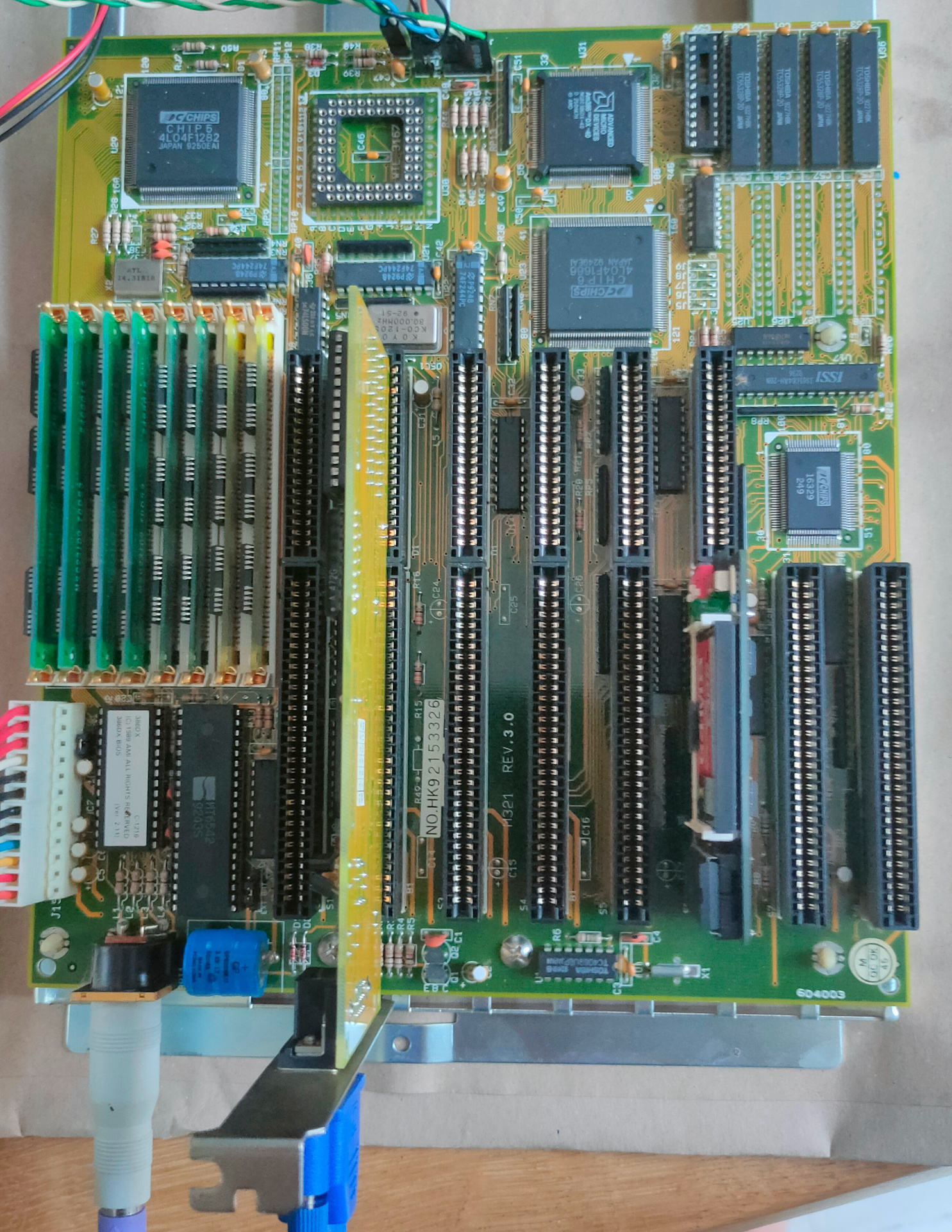
80386 (DX) Computer
Besides my 8088 and 8086 machines I needed a machine which could run our old demo’s. So I bought a new toy.
It has 8Mb Ram and runs at 40Mhz.
I’ve noticed that many of my VGA register manipulation code, can’t be run on a modern VGA monitor, I need to use a CRT for that .. Another thing to buy
Needed to fix arduino code, due to the TFT_eSPI library issues. And I’ve got a S3 with another resolution, but that was an easy fix. Then needed to reinstall nodejs with another version. Had to modify the code because the tcp server would not start. Weird errors logging, but in the end fixed … very cool
I probably end up designing a 3D printed case that looks like a monitor or tv.
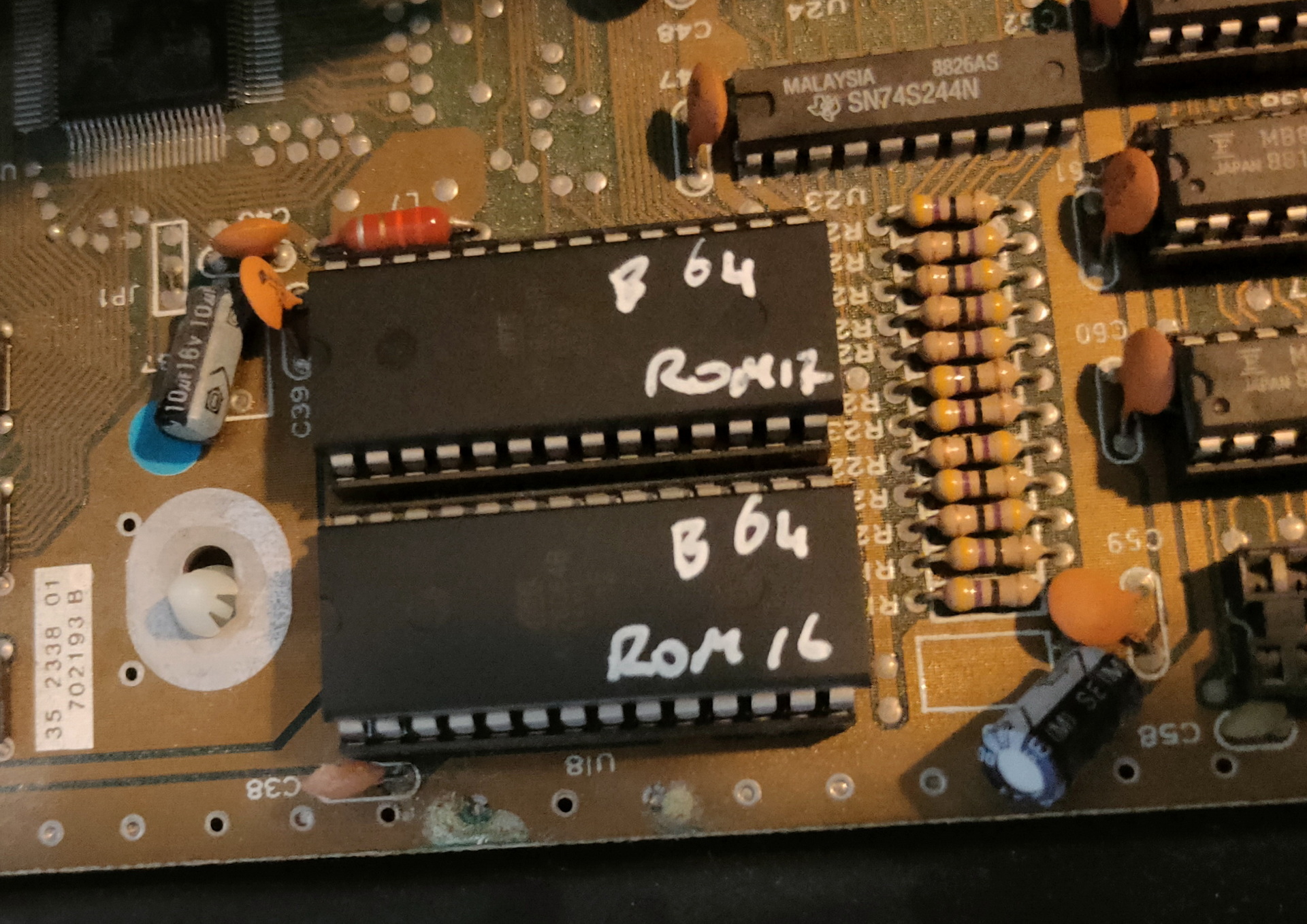
I mentioned a 2 ROM setup because the 8086 is 16bits instead of 8. So I was wondering that maybe a recompile was needed, or the data being split over two roms (odd/even)
The guy from GLABios was so kind to build me two interleaved roms.
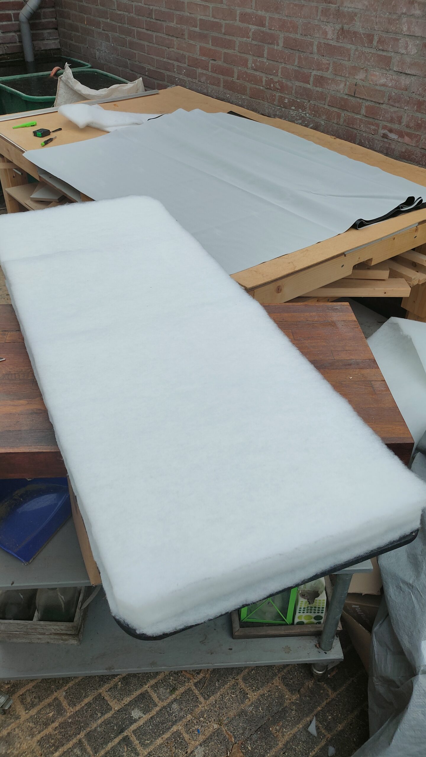
So while working on a padded bench, I tested the ROMs.
Working outside .. on the padded bench
Back to the roms, it didn’t work!
But I missed a detail in the technical manual (the bold text)
In Turbo XT /2 and Turbo XT /3, there are two 28-pin sockets for ROM, both of them are occupied by 2764 which stored the BIOS. The contents of the two 2764 are identical. One of them contribute the ODD Byte to the system and the other EVEN Byte. Together they support 16 Bit BIOS access.
I don’t know why this is how it works, but when I flashed two the same 28C64’s it worked! (I also tought that is was strange that both original roms had the same markings.
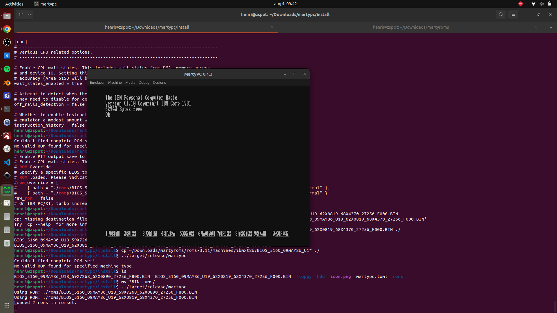
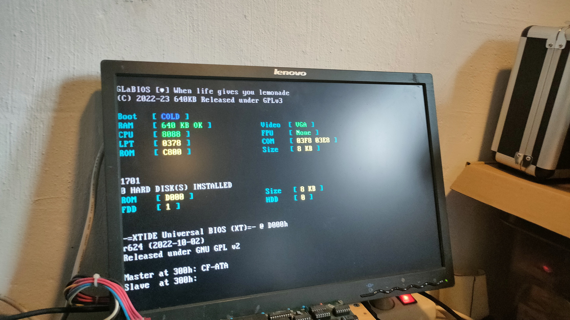
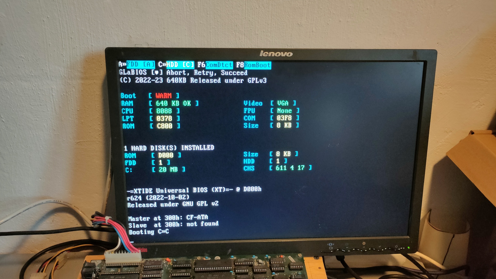
New romsGlabios shows 8088Real 8086
It workes!
Only remarks/observations:
There was a longer wait time before the CF Card was detected/accessed
GLABios mentions 8088 in the splashscreen, but the machine is a 8086
UPDATE
GLABios was not updated for displaying 8086 yet. Error 1701 was the (old spinning) harddisk not being connected.
Nice .. harddisk infomation like size, rom address and CHS
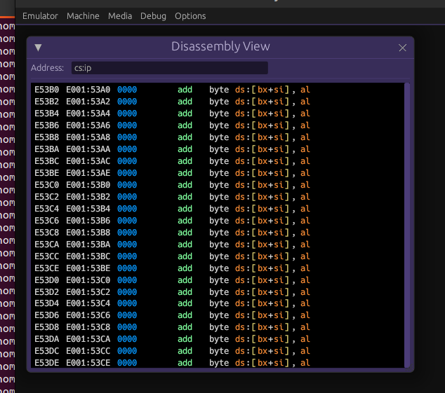
Today I was working on my own brew ISA card (wirewrapping). Did some mini modeling stuff. Sorted some pipetunes. And played around with my 8086.
Got it on a desk now, and replaced the harddisk with the CF card. Also got an old SoundBlaster working, so i wanted to see what of my old code could still run. Apparanty most code was compiled for 386/486 🙁 So i recompiled some stuff. Below a horizontal scroller example.
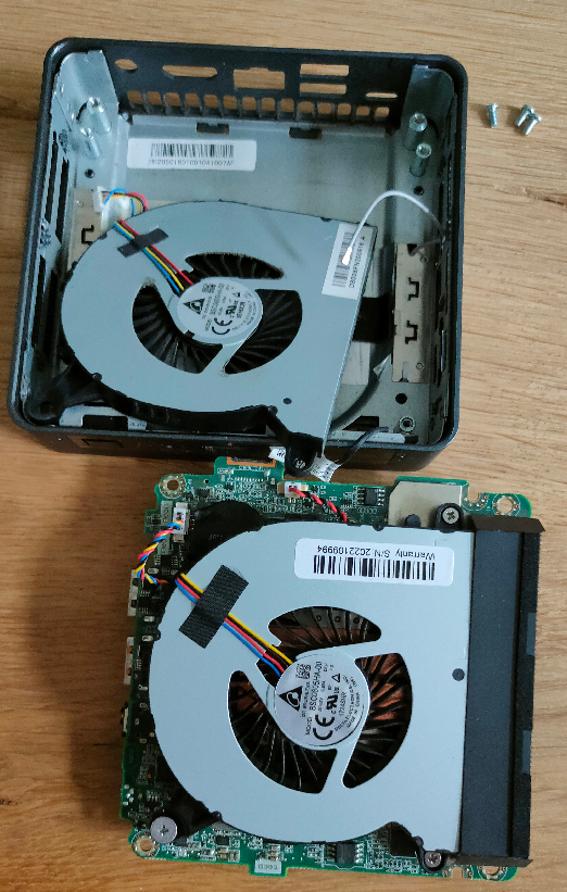
Meanwhile i got my new fans in for my NUC (Kodi player, it was making a hell of a noise due to bad ball bearings.
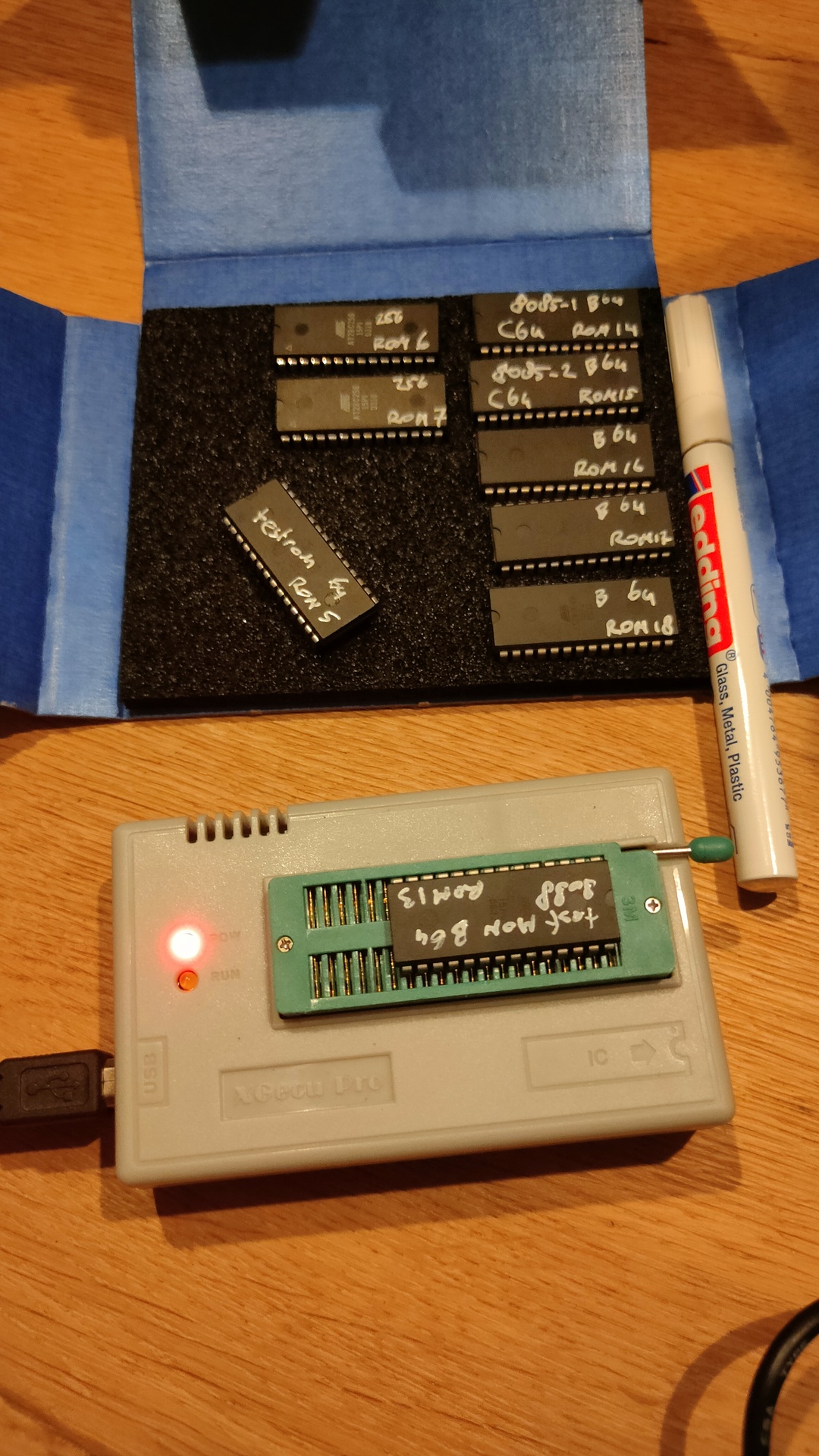
Got some new roms in. These are for my 8088/8086 the 6502 computer and C64 cartridges.
While I seldom had any problem writing to these, now I could not write one! Erasing didn´t give me an error?!?
henri@zspot:~/projects/wozmon8088/mon8086$ minipro -w mon8086.rom -p AT28C64
Found TL866II+ 04.2.129 (0x281)
Warning: Firmware is newer than expected.
  Expected  04.2.128 (0x280)
  Found     04.2.129 (0x281)
Erasing... 0.02Sec OK
Writing Code...  9.57Sec  OK
Reading Code...  0.12Sec  OK
Verification failed at address 0x0001: File=0xAA, Device=0xFF
Whenever you get this, check the markings of the chip!
Mine are AT28C64b !!!!!!!!!!!
Change your command accordingly. Another thing to watchout for is write protect, look at the commands
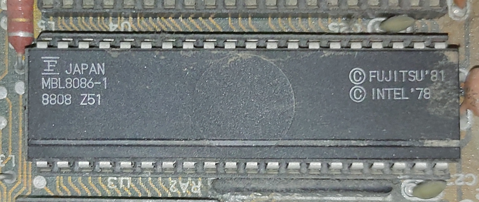
I really like GlaBios for my 8088, so today I got my Laser XT/3 8086 machine from the attic.
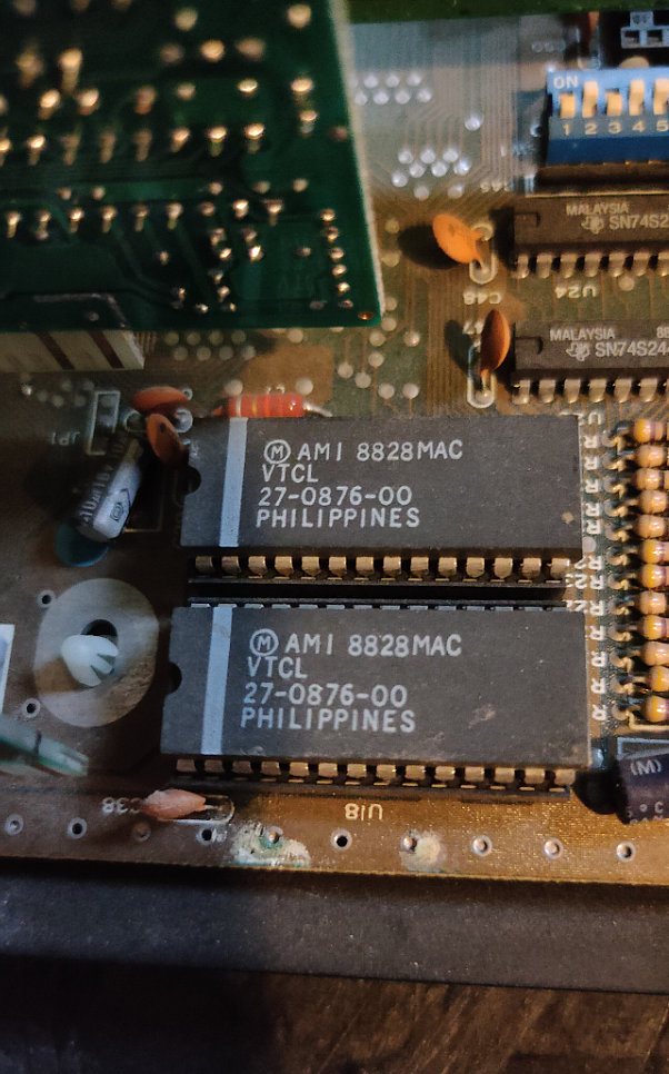
Mmm TWO ROM’s thats interesting
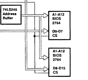
Looking futher in the schematics I found this. Apparantly there is a 8K ROM configured in a D0-D7 + D8-D15 setup. (16 bits)
Found a technical manual, this is a excerpt.
In Turbo XT, there are two 28-pin sockets for ROM, one of them is occupied by a 2764 which stored the BIOS (Basic Input Output System). The other empty socket is used to house a 32K ROM, such as the BASIC ROM
And about the XT/3 version which I have.
In Turbo XT /2 and Turbo XT /3, there are two 28-pin sockets for ROM, both of them are occupied by 2764 which stored the BIOS. The contents of the two 2764 are identical. One of them contribute the ODD Byte to the system and the other EVEN Byte. Together they support 16 Bit BIOS access.
This could be an interesting chat with Greg ..
Meanwhile i’m going to look how to split a rom into odd/even. Maybe i have to write a little python program for this.
Well, thats enough for today.
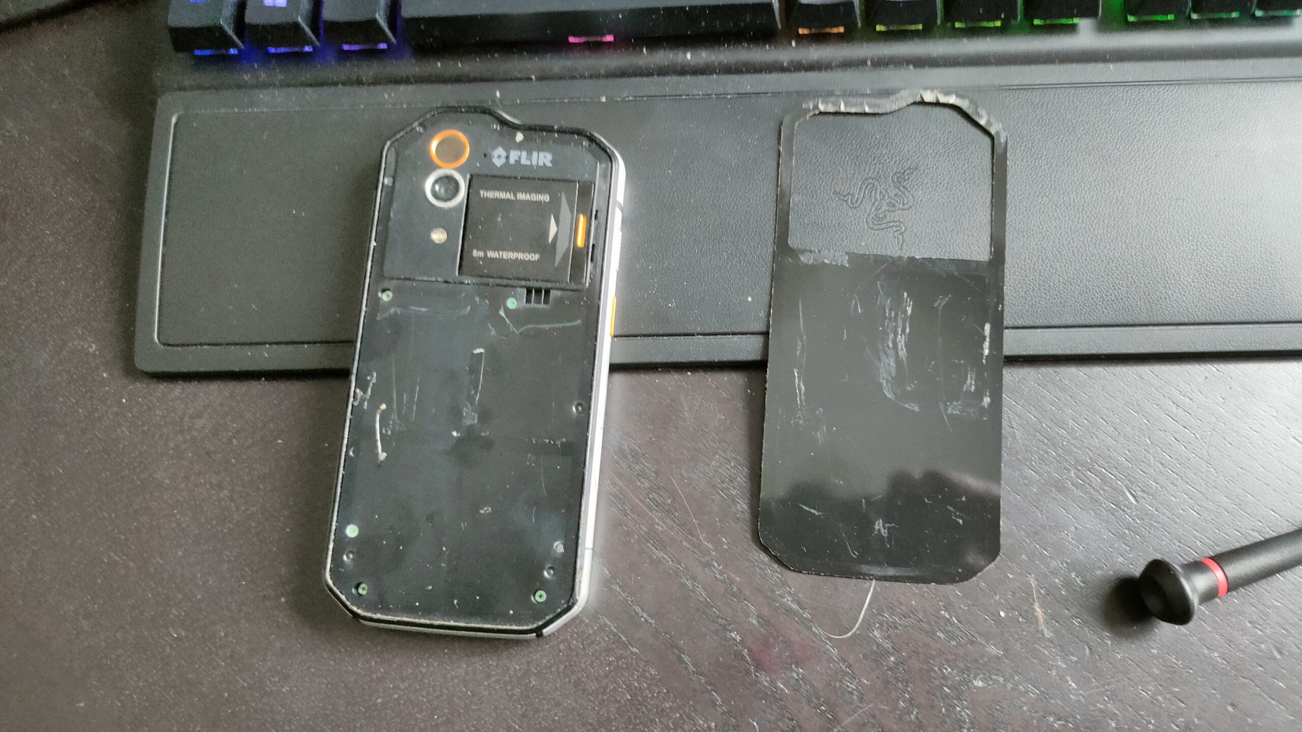
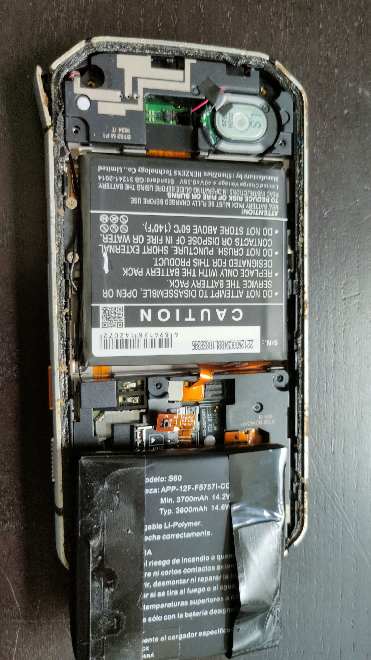
Lets fix my Cat S60 Flir phone, so i can track the hedgehog in our garden. (Battery replacement and powerbutton fix)
Hard to remove backcover and a sh*tload of screwsAt least the battery replacement was a breeze
I fixed several phones before, (broken screen. touch not working). But I hate how some manufacturers build them.
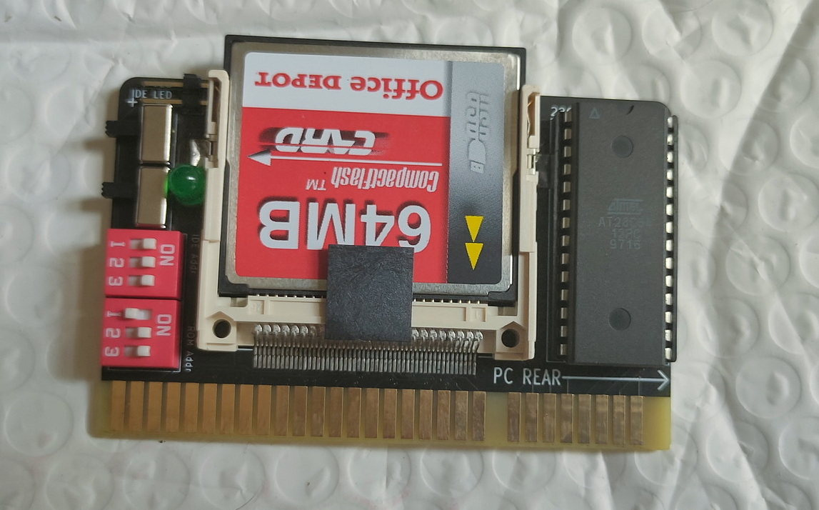
It’s fitted with a 64Mb card. Note: the XT at my parents place had a 20Mb harddisk!
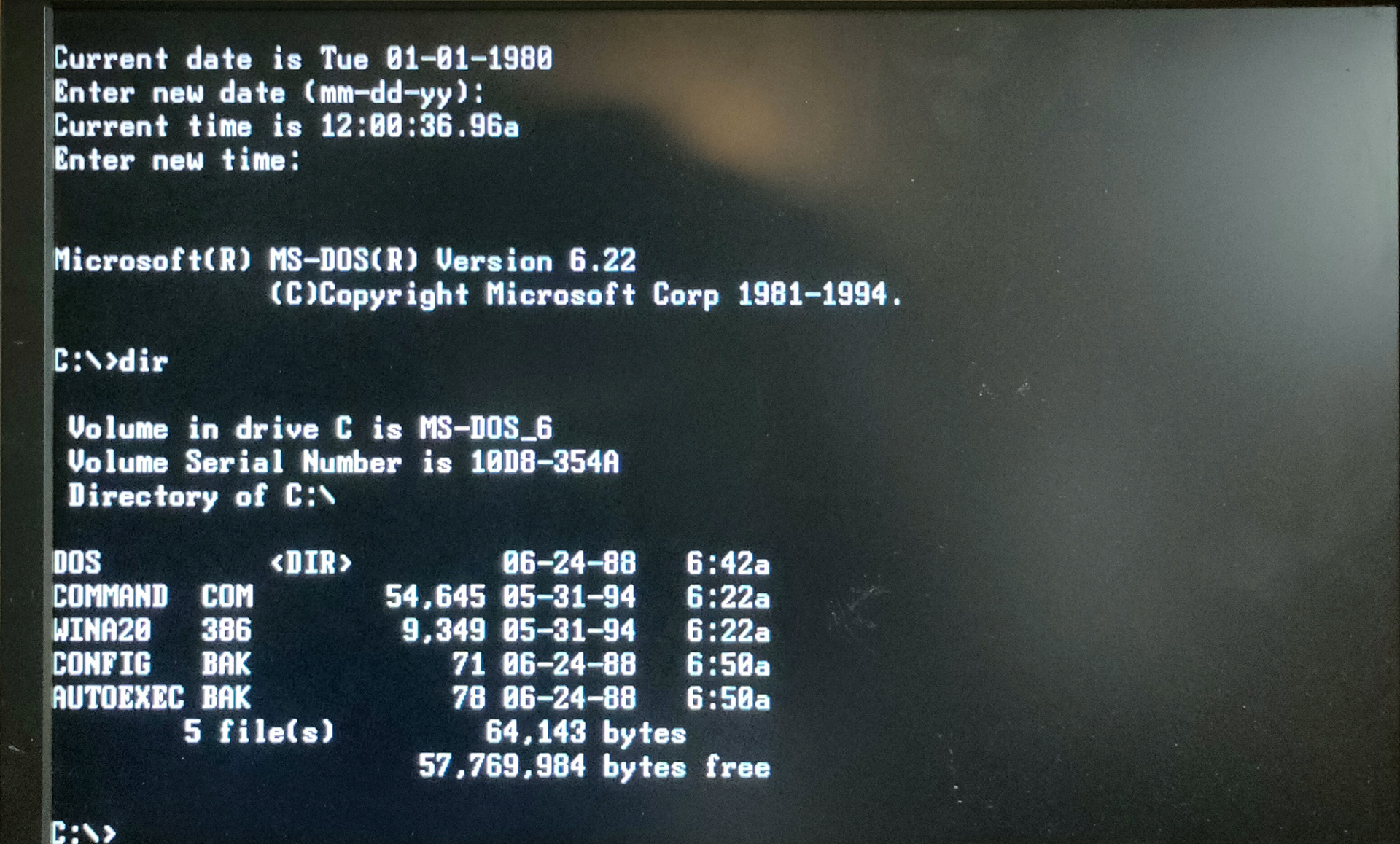
It can boot / emulate a harddisk with MsDos installed.
Replace an old or dead hard drive in a vintage PC with a hassle-free, reliable CompactFlash card! Plug-in and go! (well, as much as you can expect with these old machines)
Brand new! Built and tested.
Open Source!
This bootable expansion card provides a Compact Flash card interface to 8-bit ISA systems such as PC/XT. Typically paired with a 64MB or 1GB CF card. Silent, and more reliable than an old mechanical hard drive.
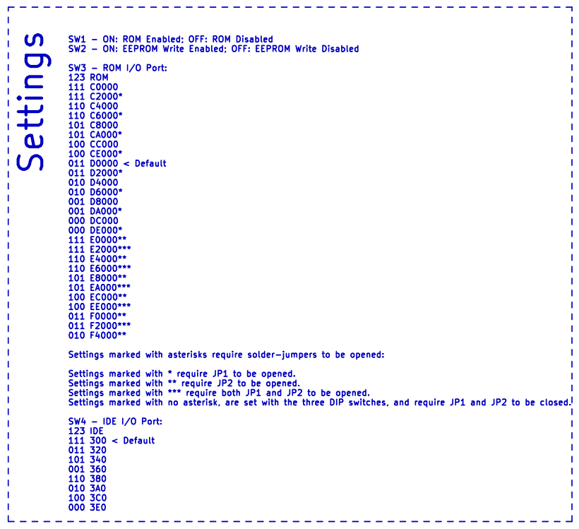
By default the XT-IDE BIOS comes configured for: XT(and higher)-compatible BIOS. Use the XT-CF-Mini’s IDE interface at 300h, no IRQ. Boot first hard drive unless user presses A for floppy. Any of the above can be changed with the simple DOS utility and built-in switches.
Switches and jumpers control: I/O port for the 8-bit IDE (CF) interface I/O port for the Option ROM Option ROM Enable Option ROM Write-protect
Note: Not all CF cards will work. Most work, but some don’t adhere to the CF standard fully, and won’t work. The full size XT-IDE card with an IDE>CF adapter, is compatible with more CF cards.
https://github.com/Bluelavasystems/XT-IDE-CF-MINI XT-CF-Mini Pcb designed by Monotech Pc’s and released opensource GNU General Public License v3.0
It is from Blue Lava Systems, who took the schematics from Sergey Kiselev, who took the design from James Pearce.
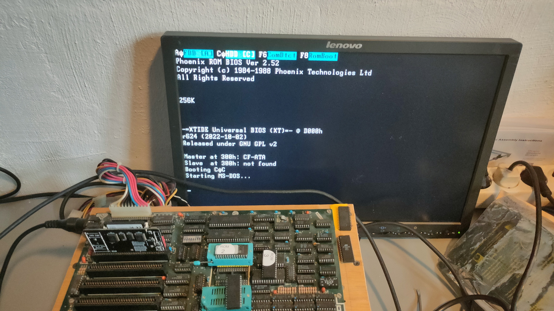
The harddisk extension is XT-IDE Universal BIOS. And can be flashed.
ROM address D0000, and IO port 300h does not need a IRQ
After installing this on my 8088/v20 motherboard I tested this with GlaBIOS, but it gave me one beep, and after that it woukd reset the machine.
Testing with the original Phoenix Bios and PCXtBios worked for me.
UPDATE: Bad contacts and a eeprom I didn’t trust. Greg gave me version 0.2.5 of Glabios, which I burned to a new eeprom. And I cleaned some contacts. (Checksum rom changed with every reset)
The Card and my extension bios both run with all bios-ses
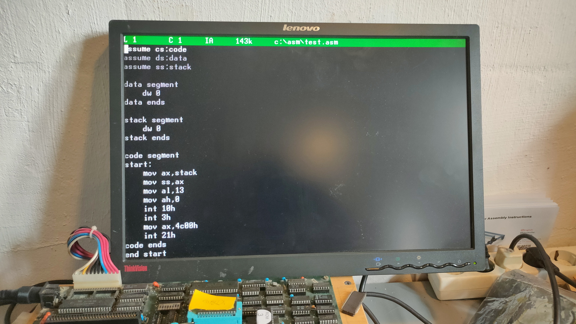
While doing some wood work, routing and painting. I managed to have some time to experiment with my PC200.
The Amstrad PC20 / Sinclair PC200 was a home computer created by Amstrad in late 1988. The machine was available in two versions, Sinclair PC200 and Amstrad PC20. (US/UK?)
The limited CGA graphical capabilities and PC speaker sound output were greatly inferior compared to other home computers of the time. I has a modulator to connect a TV and could do hercules graphics on a sub-9 interface.
I got this computer a long time ago. (I still have to post pictures of my collection and getting them out of storage)
Info about this machine:
Build in 1988, Intel 8086 @ 8Mhz 512KB memory 3.5″ Floppy drive TV Modulator Pal 640×200 CGA and Hercules
PC200
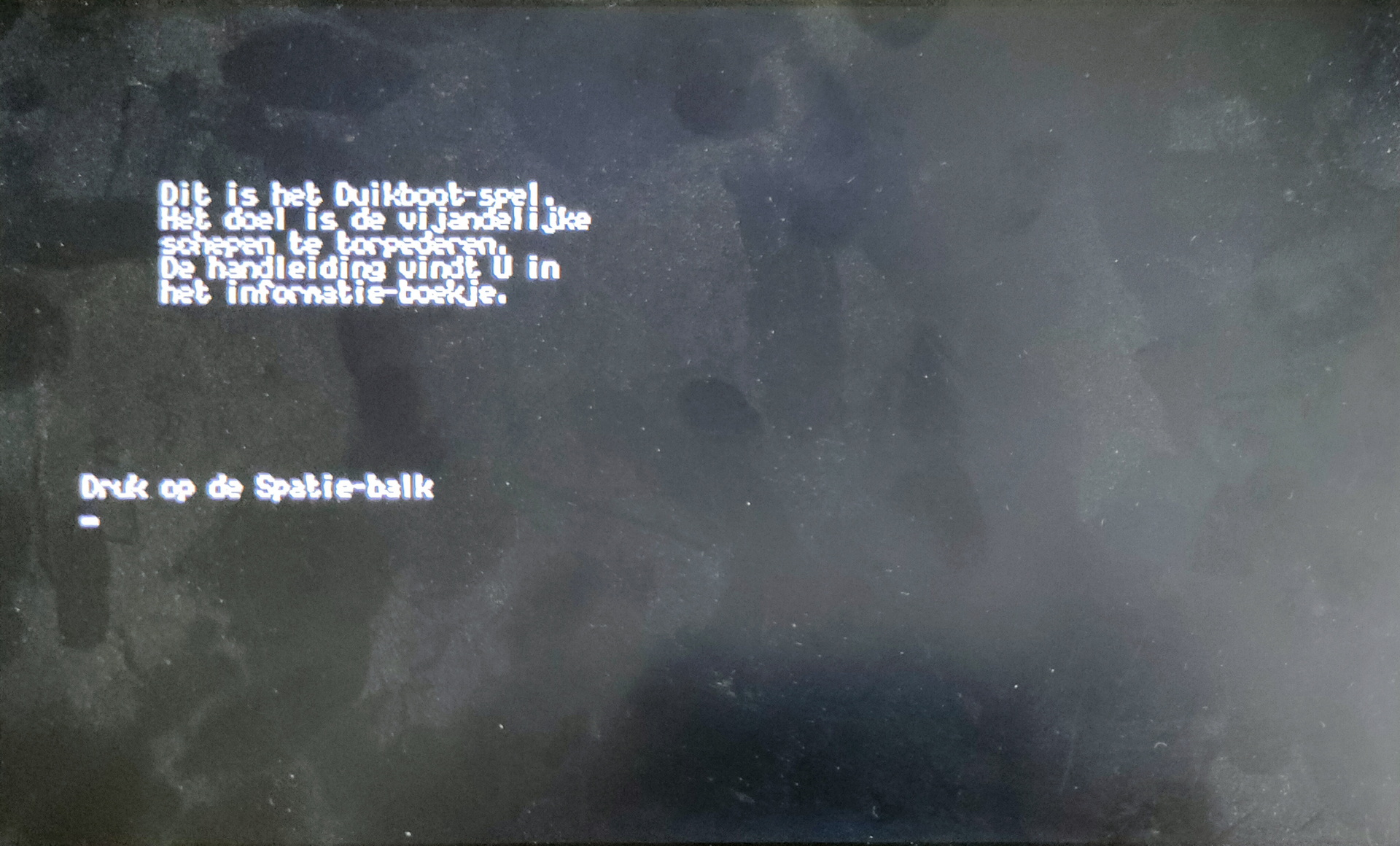
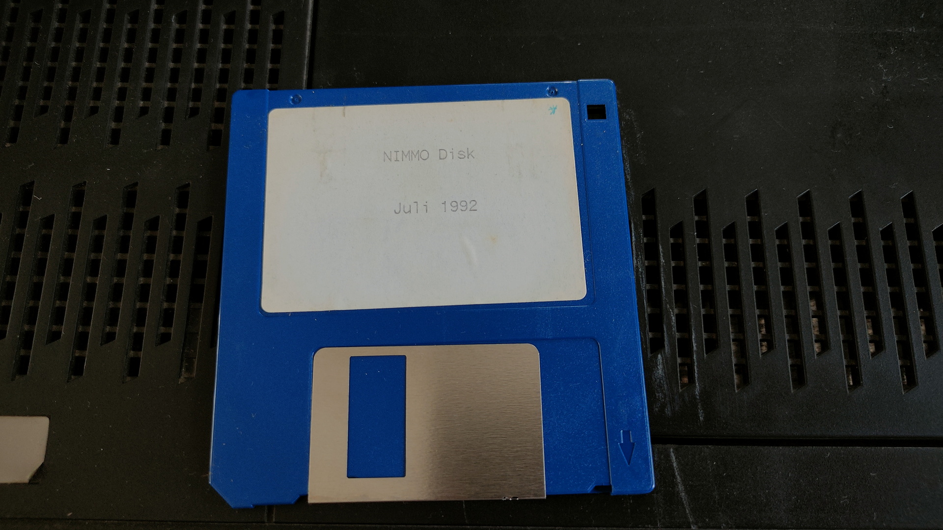
It still had a floppy in its drive, NIMMO Disk Juli 1992
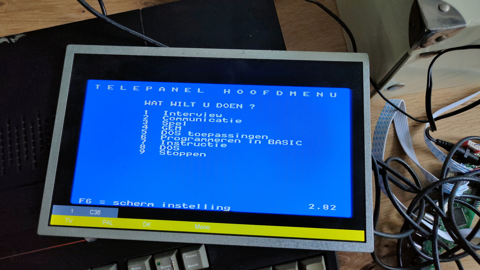
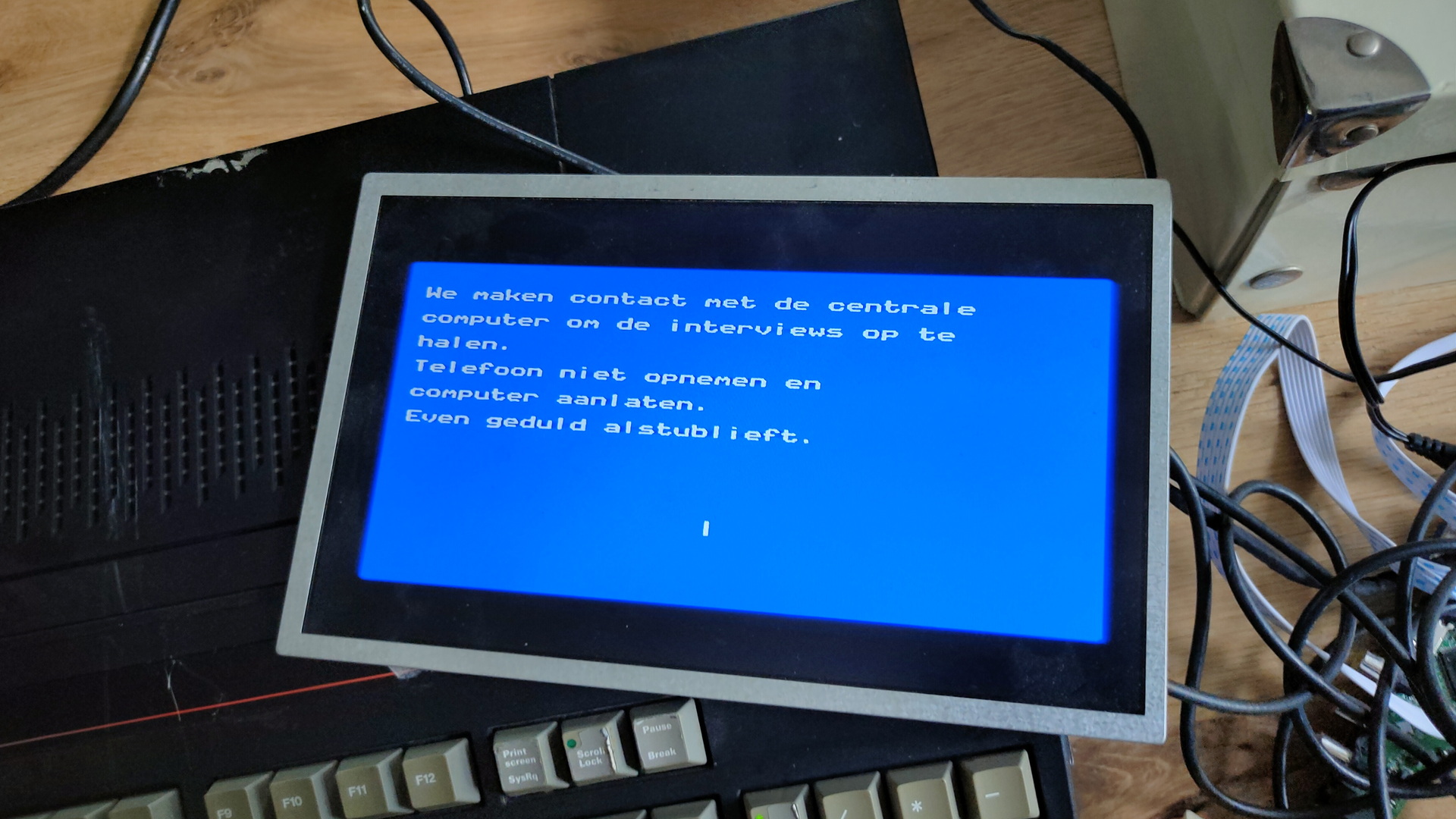
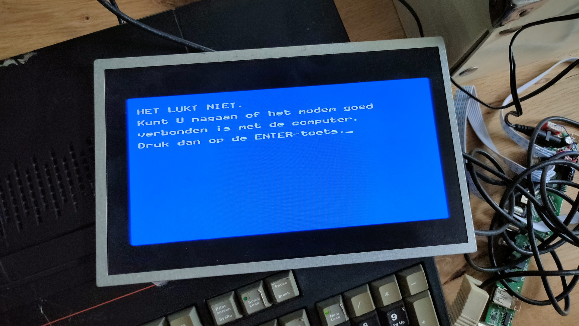
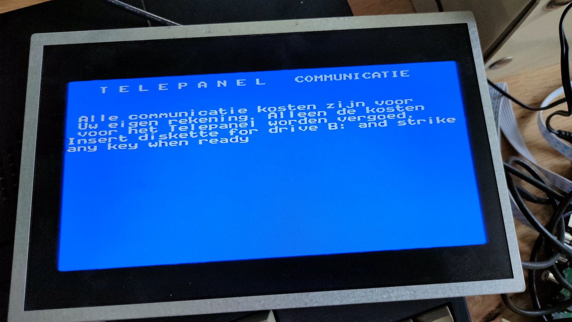
Apparently this machine was used with a modem to do some interviewing for the University Amsterdam using Telepanel/Interview!
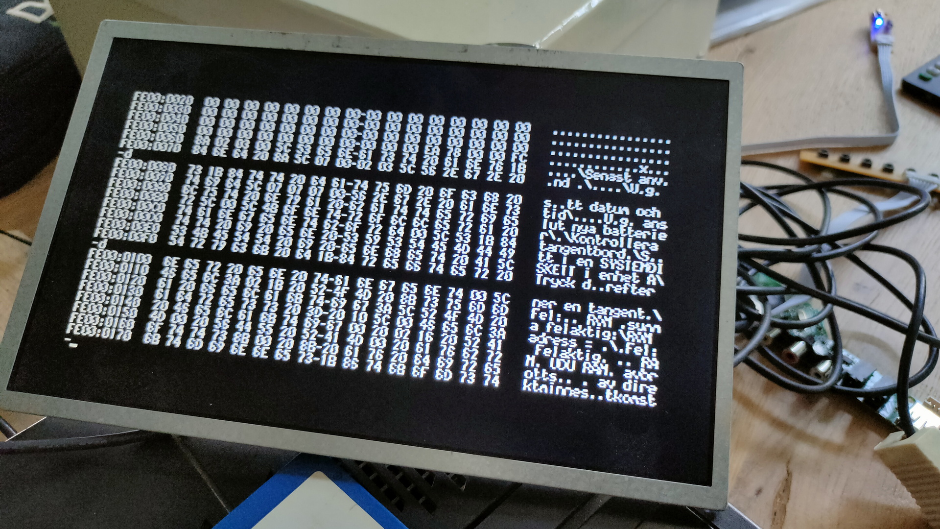
The ROM has several language options which you could set with dipswitches.
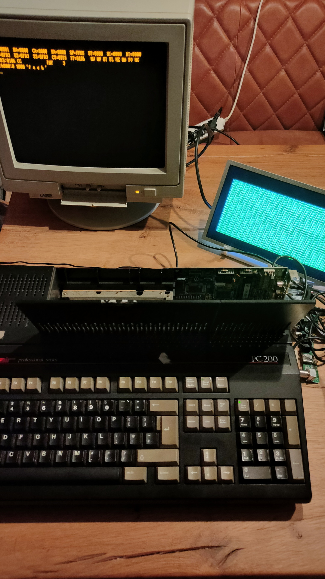
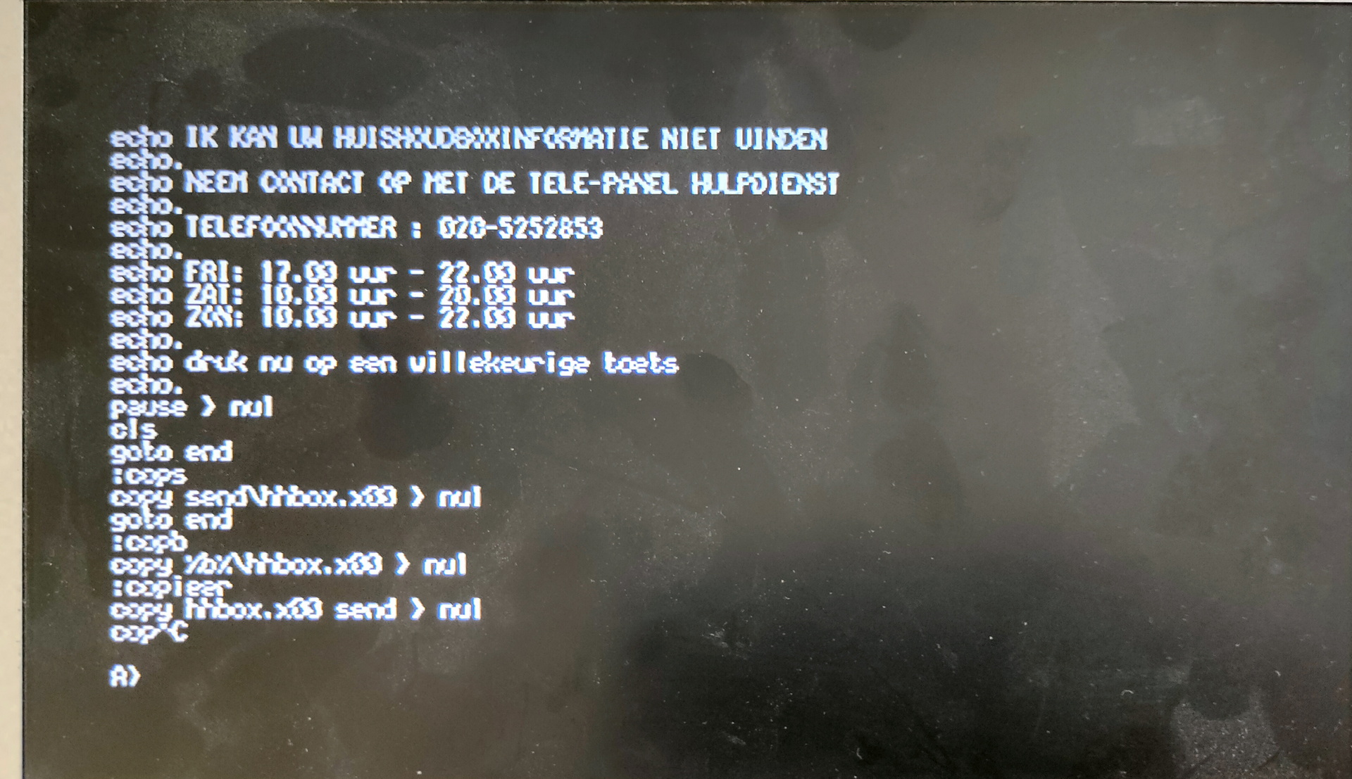
Debug part of ROM
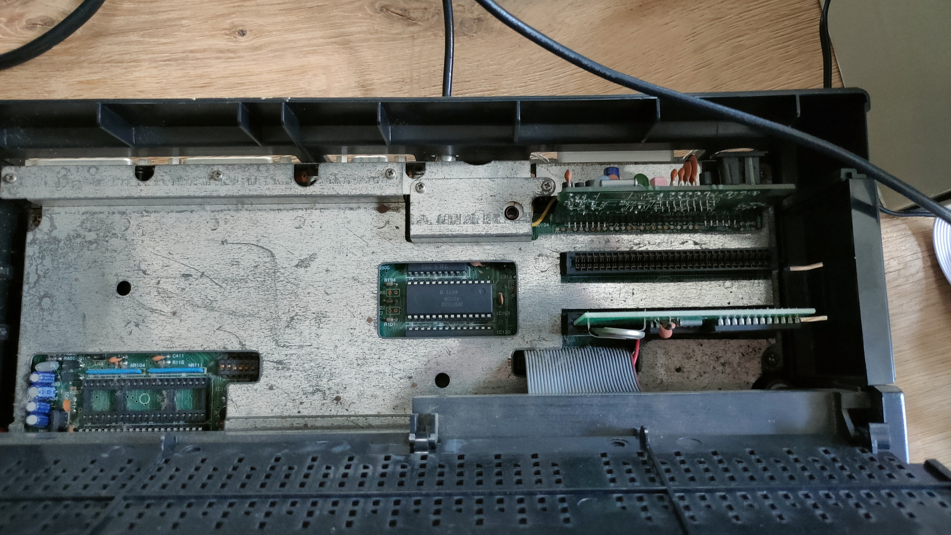
Besides the machine having a “amiga” like case, it has two ISA slots behind a little trapdoor! How cool is that!
Dirty view of the ISA slots (One containing a RTC card)
Enabling only CGA on the machine and plugging in a Hercules card, you can do Multiscreen! CGA and MDA addresses don’t conflict! And if the ROM supports it .. dual screens baby!
Left Hercules and Right CGA
I used a debug command to fill the right screen
f b800:0 1000 ‘f a s h’
Cool little machine
Running old masm/precompiled machine code crashes. I’ll have to look into that.
"If something is worth doing, it's worth overdoing."