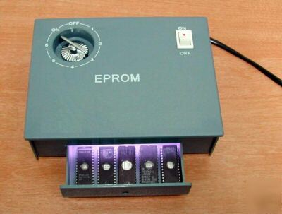
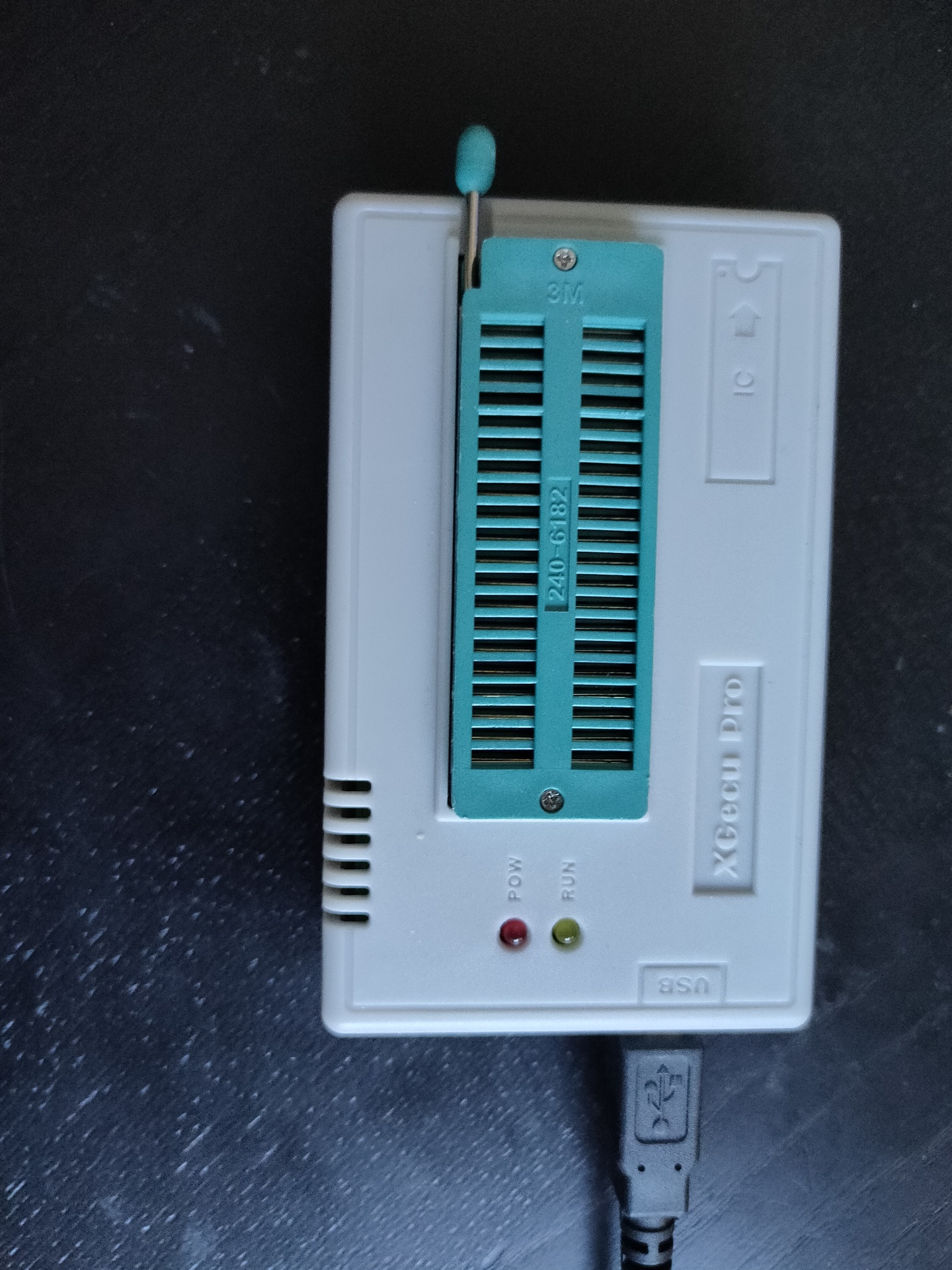
Flashing ROMs .. (eeproms). It used to be a pain in the *$$. Burning took a looong time. But clearing one with UV took .. 20 minutes or so. Using one of these:
Altered clock module
Changed button press
Dipswitches for more speed control (red .. upper left)
Changed Rom/Ram
Changed addressing
Added RAM
ZIF Socket for ROM
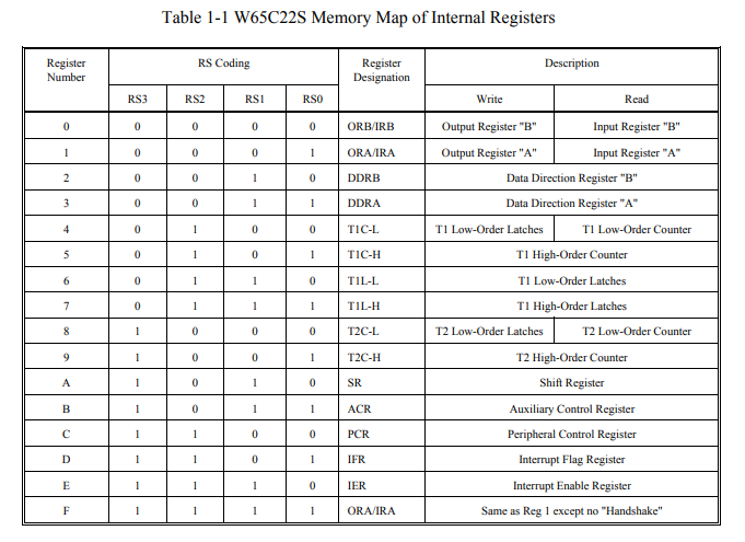
VIC 6522
Fixed clock
Added buttons for interrupt
Display
Display works now
To test: Create Address logic to access display without VIA Can work, but not at high speed clock. Stays behind VIA
To buy: st7920 lcd 128×64
Generic improvements
Rewired most parts, using color codes (Blue data, Yellow Address and so on)
Added leds on data and address bus using ULN2803 darlington arrays
100nF Decoupling capacitors on the power rails
To do’s or ‘have to look into’s’
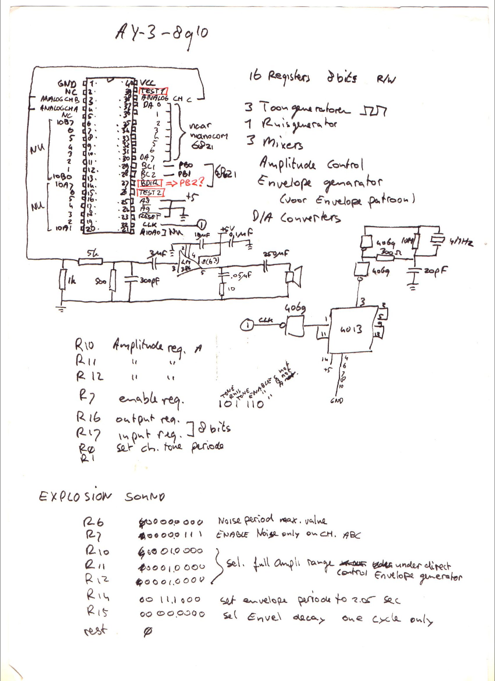
For sound i planned to use a General Instrument AY-3-8910, it is somewhere in my Lab, i know it is. I saved this chip and a SID for my Amiga addon soundcard. Where are my plans for the simple v1 setup? (FOUND IT)
I have to start writing rom functions for display usage. Like JSR $ff00 – Clear screen subroutine .. etc
I’m scraping information from websites, to get started on my clock controller. ATmega328 with ssd1306 display and rotary encoder/dip switches
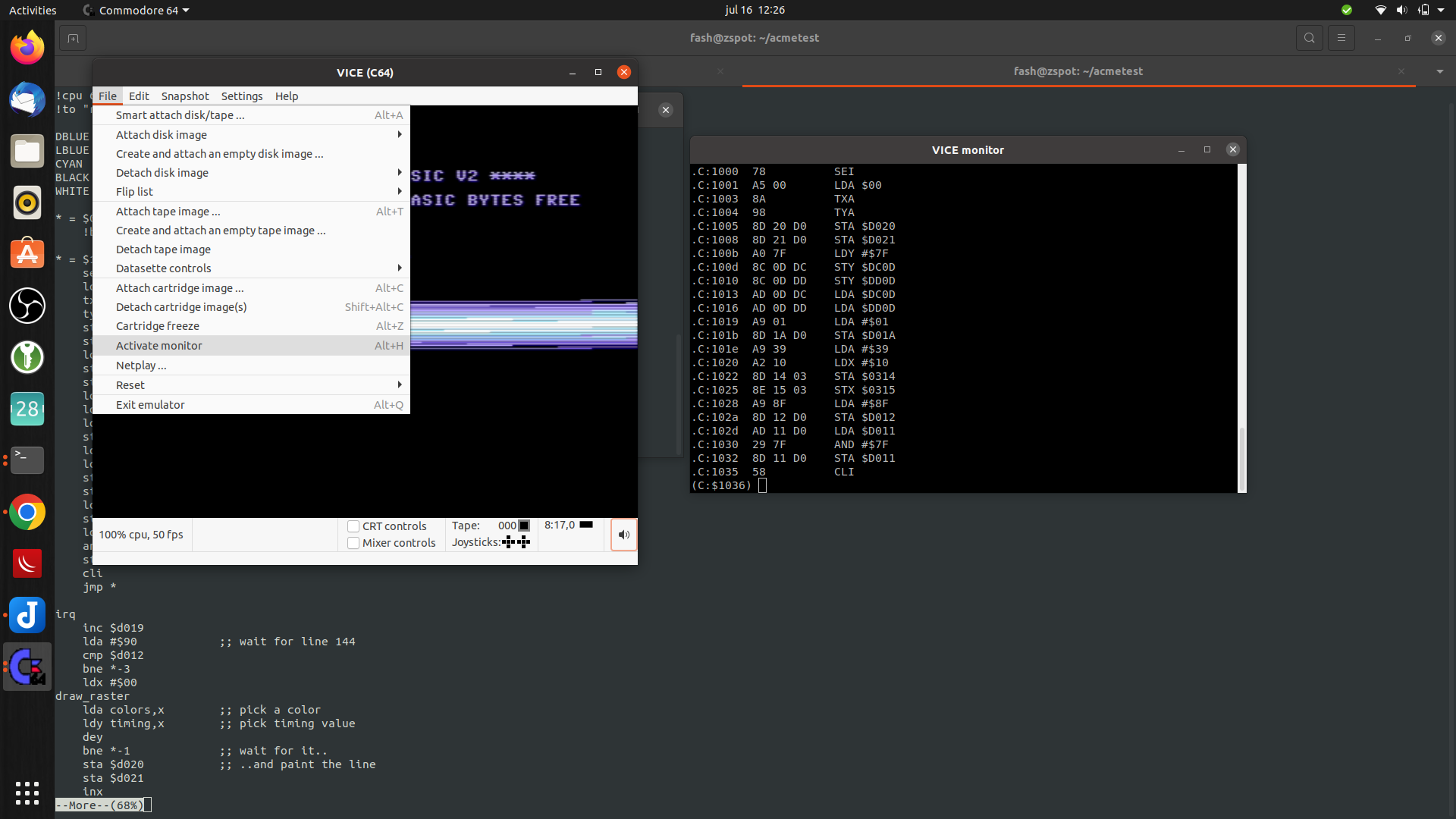
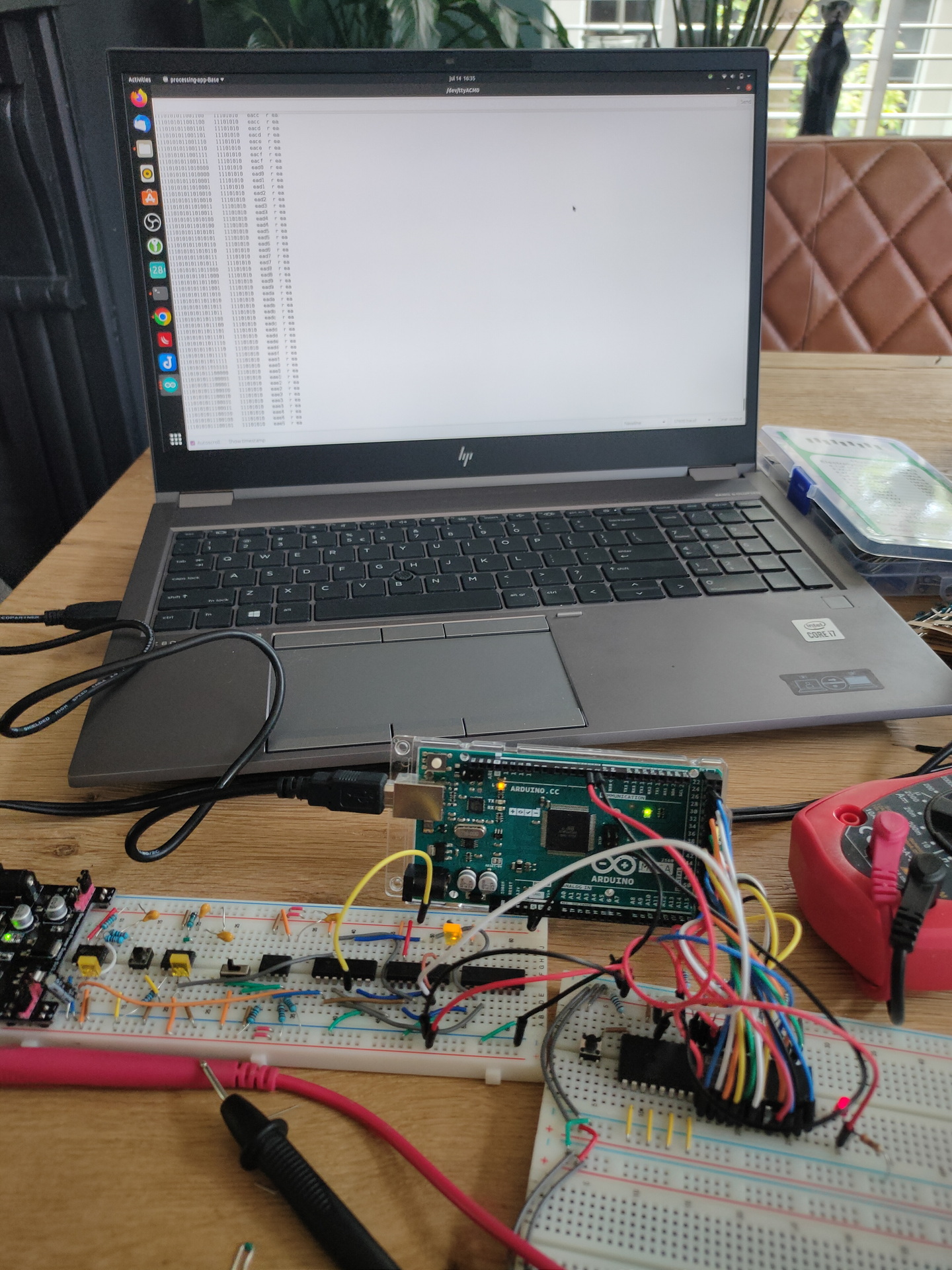
Notes about the movie: Left side is Arduino IDE monitor reading Addressbus and Databus. (I’m going to try to rewrite this to realtime disassemble) Resetting system. Stepping CPU with manual clock pulses. Start vector being read at $FFFC/$FFFD. Program being run from $8000. Set clock on automatic ( ~ about 150 Hz ) Last opcodes you see a JMP loop 4C 2F 80, that is JMP $802F Display enlarged on video, was not visible on movie i took on mobile. (Wrong angle?)
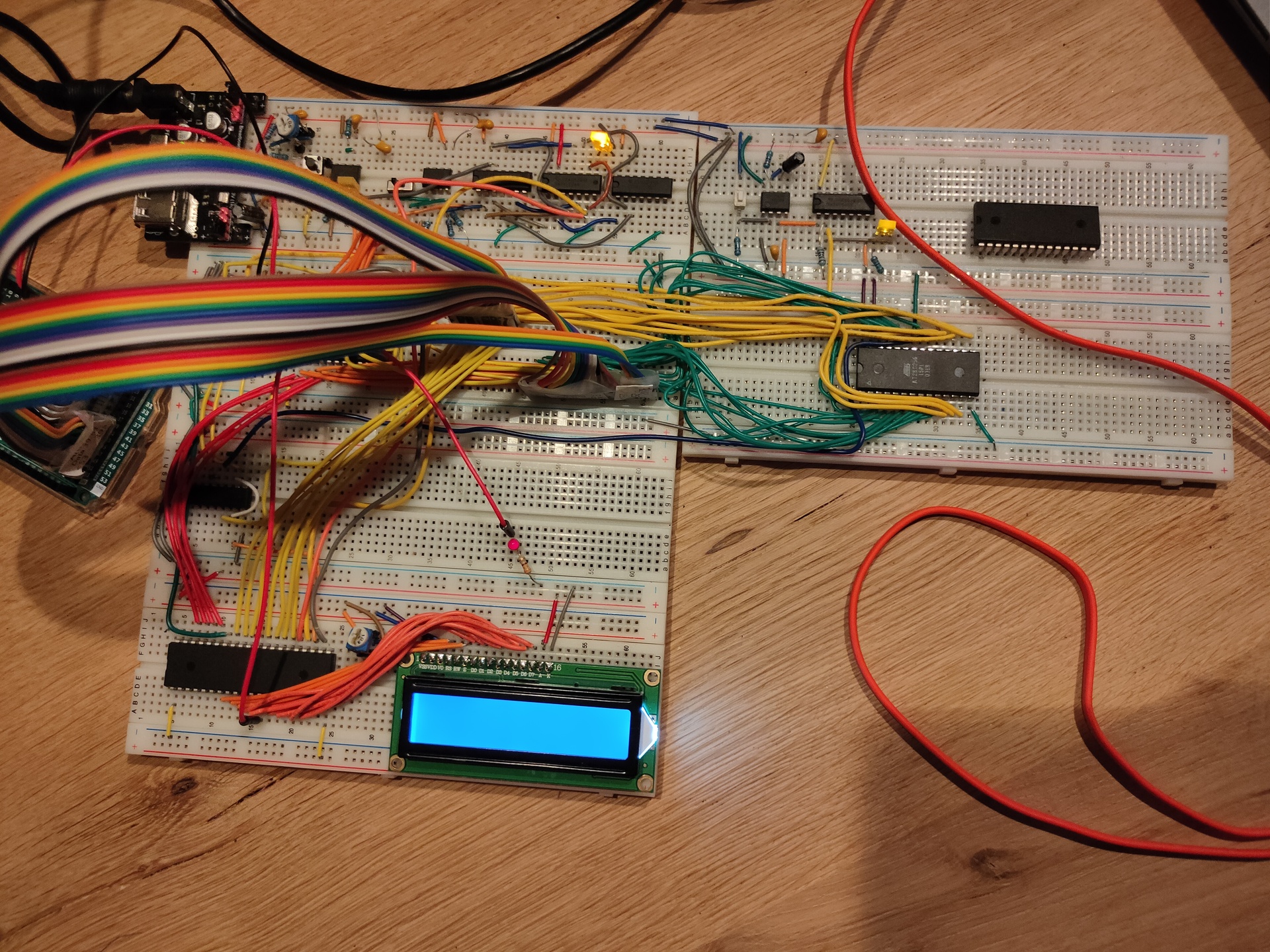
Breadboard overview
Clock module
Reset module + Crystal
CPU + nmi/int buttons
RAM and ROM
Address decode + Bus divide
Addres/Data bus leds
6522 VIA + Display
2nd via + Buttons
?
(sound board)
TIL: 6502 can run without ram only rom,expect when using JSR … which uses a program stack in RAM
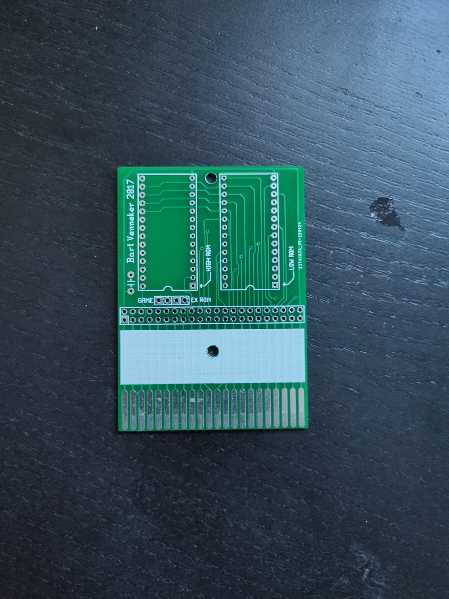
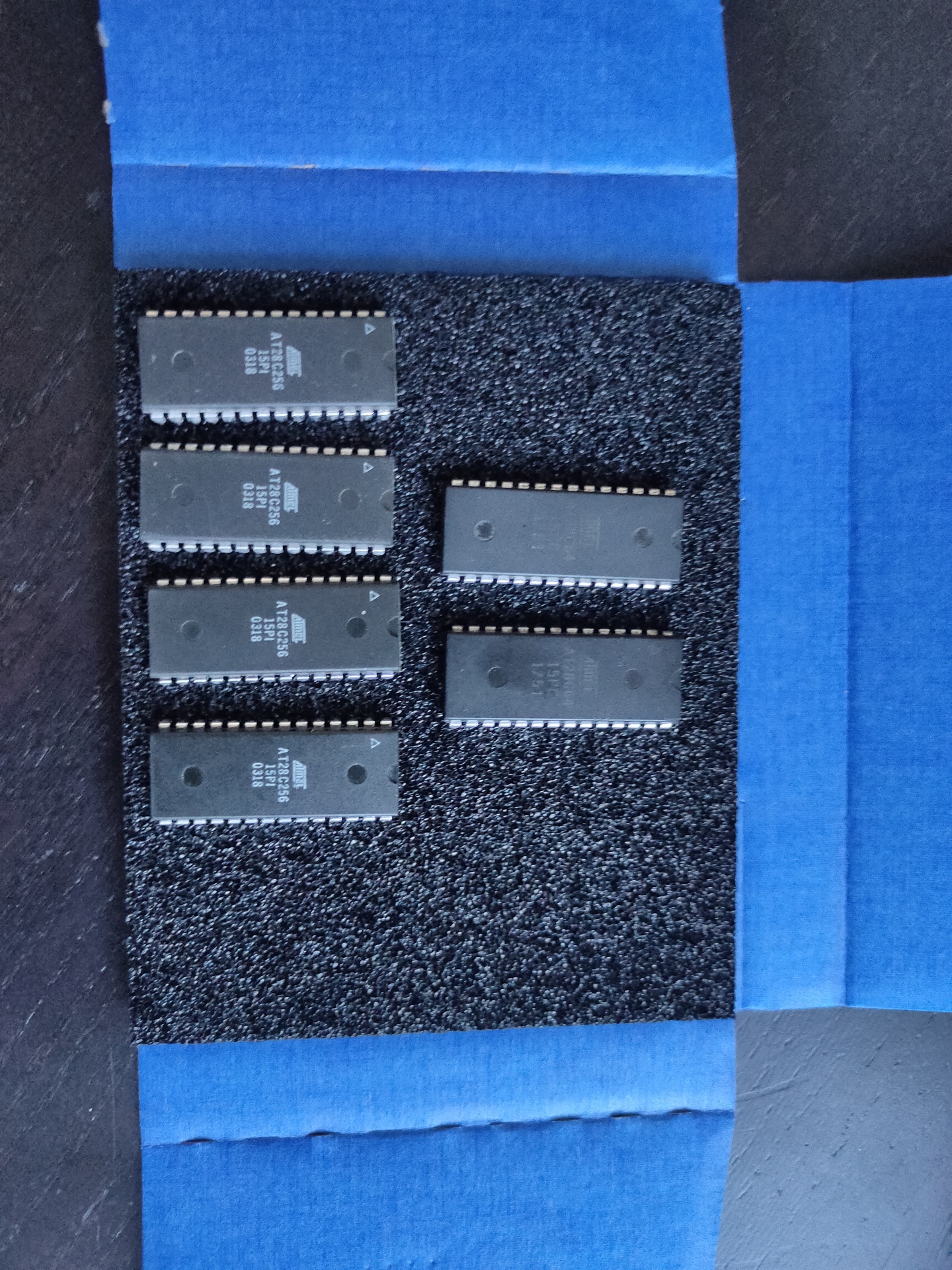
Cartridge printEeproms 8k and 32k (also for 6502 project)Eeprom programmer
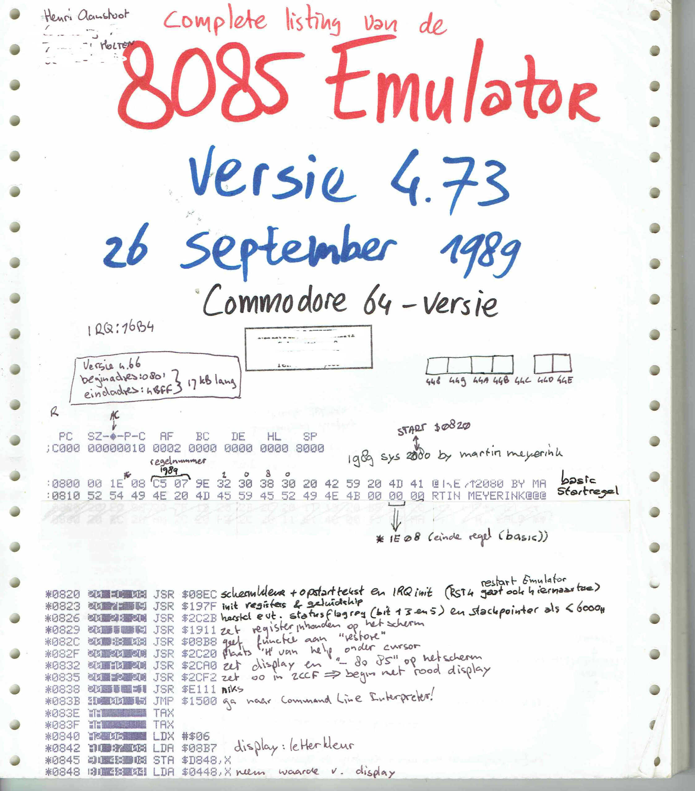
I’ve got the tools and Bigred made me enthusiastic again. My goal is to make a C64 Cartridge from a PRG. And Not any program, it is the 8085 Emulator from Sepp.
Serveral problems i have to ‘fix’
The program is 17K, Cartridges can only be 16K. So i have to use 2x 8K and compress the data. This means it have to be uncompressed at start time. ( I was thinking of using exomiser for this )
Program starts normally at $0820 and probably is not optimised to run anywhere else. So a starting routine has to copy the program from cartridge memory to the correct location
Luckily i have the source! How cool is that
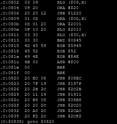
For version 4.73 it states : Starting at $0820 .. but my hexdump is off by one??!?
00000020 00 20 ec starts with 00 at $0020 .. and not 20 ?!?!
Tools used until now:
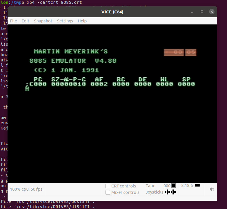
Vice – C64 Emulator x64 -cartcrt 8085.crt
c1541 – Linux disk tool for C64 images. Used this to extract the 8085emulator PRG
prg2crt.py – a convertor from PRG to a cartrid file which can be used by Vice python2 prg2crt.py 8085.prg 8085.crt
minipro – eeprom programming tool for Linux minipro -p AT28C64 -w /tmp/test.bin
cartconv (tool from vice to convert crt <-> bin) cartconv -t normal -i test.bin -n ‘my cart’ -o test.crt
xa – Cross assembler 65xx/R65C02/65816
ACME – the ACME Crossassembler for Multiple Environments
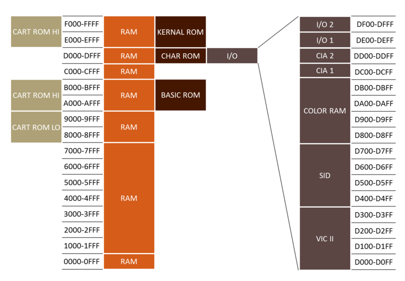
Memory Map C64 – source c64-wiki.com
Card Low starts at $8000, so that’s the place where those roms are going to be. To place on this address:
Copy routine : from ($8000 + this copy routine) to $0820 When to decompress?? jmp routine to $0820
A cartridge file >16K and with his emulation headers seems to work??!
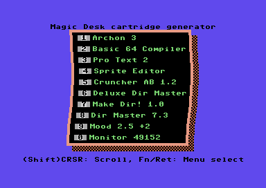
Also nice: Magic Desk Cartridge Generator V3.0
UPDATE: 20220811
exomizer sfx 0x0820 8085.prg -o data.exo # Compress and start at 0x0820
xa frame.asm -o frame.bin # Add code and write binary
x64 --cart16 frame.bin # Test cartridge with Vice
frame.asm
;----------------------------------------------------------
; example usage
; xa frame.asm -o frame.bin
; cartconv -t normal -i frame.bin -n 'my cart' -o frame.crt
; x64 -cartcrt frame.crt
;----------------------------------------------------------

;no load-adress for bin-file, so no header here

*=$8000
.word launcher ;cold start
.word launcher ;warm start
.byte $c3	;c
.byte $c2	;b
.byte $cd	;m
.byte $38	;8
.byte $30	;0

launcher
  stx $d016
  jsr $fda3	;prepare irq
  jsr $fd50	;init memory
  jsr $fd15	;init i/o
  jsr $ff5b	;init video
                ;make sure this sets up everything you need,
                ;the calls above are probably sufficient
  ldx #$fb
  txs

;set up starting code outside of cartridge-area
move_starter
  ldx #(starter_end-starter_start)
loop1
  lda starter_start,x
  sta $100,x
  dex
  bpl loop1
  jmp $100
;---------------------------------
starter_start
  ldx #$40 ;64 pages = 256 * 64 = 16384 Bytes
  ldy #0
loop
src
  lda exomized_data,y
dst
  sta $801,y
  iny
  bne loop
  inc src+2-starter_start+$100
  inc dst+2-starter_start+$100
  dex
  bpl loop

;make sure settings for $01 and IRQ etc are correct for your code
;remember THIS table from AAY64:

;       Bit+-------------+-----------+------------+
;       210| $8000-$BFFF |$D000-$DFFF|$E000-$FFFF |
;  +---+---+-------------+-----------+------------+
;  | 7 |111| Cart.+Basic |    I/O    | Kernal ROM |
;  +---+---+-------------+-----------+------------+
;  | 6 |110|     RAM     |    I/O    | Kernal ROM |
;  +---+---+-------------+-----------+------------+
;  | 5 |101|     RAM     |    I/O    |    RAM     |
;  +---+---+-------------+-----------+------------+
;  | 4 |100|     RAM     |    RAM    |    RAM     |
;  +---+---+-------------+-----------+------------+
;  | 3 |011| Cart.+Basic | Char. ROM | Kernal ROM |
;  +---+---+-------------+-----------+------------+
;  | 2 |010|     RAM     | Char. ROM | Kernal ROM |
;  +---+---+-------------+-----------+------------+
;  | 1 |001|     RAM     | Char. ROM |    RAM     |
;  +---+---+-------------+-----------+------------+
;  | 0 |000|     RAM     |    RAM    |    RAM     |
;  +---+---+-------------+-----------+------------+

  lda #$35 ;cart is always on instead of BASIC unless it can be switched off via software
  sta $01
  jmp $80d ;for exomizer, i.e.

starter_end
;----------------------------------
exomized_data
.bin 2,0,"data.exo"
;syntax for exomizer 2.0.1:
;exomizer sfx sys game.prg -o data.exo
main_file_end
;fill up full $4000 bytes for bin file ($c000-$8000=$4000)
.dsb ($c000-main_file_end),0
Exomiser info
 Reading "8085.prg", loading from $0801 to $4CE9.
 Crunching from $0801 to $4CE9.
Phase 1: Instrumenting file
-----------------------------
 Length of indata: 17640 bytes.
 [building.directed.acyclic.graph.building.directed.acyclic.graph.]
 Instrumenting file, done.

Phase 2: Calculating encoding
-----------------------------
 pass 1: optimizing ..
 [finding.shortest.path.finding.shortest.path.finding.shortest.pat]
  size 80273.0 bits ~10035 bytes
 pass 2: optimizing ..
 [finding.shortest.path.finding.shortest.path.finding.shortest.pat]
  size 80039.0 bits ~10005 bytes
 pass 3: optimizing ..
 Calculating encoding, done.

Phase 3: Generating output file
------------------------------
 Encoding: 1101112133423160,1122,2010223445667788,032144406789BBCD
 Length of crunched data: 10034 bytes.
 Crunched data reduced 7606 bytes (43.12%)
 Target is self-decrunching C64 executable,
 jmp address $0820.
 Writing "data.exo" as prg, saving from $0801 to $304C.
Memory layout:   |Start |End   |
 Crunched data   | $07E7| $2F18|
 Decrunched data | $0801| $4CE9|
 Decrunch table  | $0334| $03D0|
 Decruncher      | $00FD| $01C0| and $9F,$A7,$AE,$AF
 Decrunch effect writes to $DBE7.
Decruncher:  |Enter |During|Exit  |
 RAM config  |   $37|   $37|   $37|
 IRQ enabled |     1|     1|     1|
UPDATE:20230126
; CODE COPY FROM http://www.lemon64.com/forum/viewtopic.php?t=60786&sid=2559442c8b963d7aac27cb13b493f372
; Thanks for posting: Richard of TND
; this is for a 16KB cart, using ACME!!

      !to "mycart.crt",cart16crt

scr = $0400

DecrunchADDR = 2061 ;SYS 2061   (HEX $080D)

      *=$8000
      !word launcher
      !word launcher
      !byte $c3,$c2,$cd,$38,$30 ;CBM 80


launcher
   sei
   stx $d016
   jsr $fda3 ;prepare irq
   jsr $fd50 ;input memory
   jsr $fd15 ;initialise i/o
   jsr $ff5b ;initialise video memory

;For a more professional boot up. Make
;the border and screen black. AFTER
;the video memory, etc has finished.

   lda #$00
   sta $d020
   sta $d021
   cli

;Switch off the screen.

   lda $d011
   and #%11101111
   sta $d011

;Move transfer code over to the screen
;memory.

   ldx #$00
tloop   lda transfer,x
   sta scr,x
   inx
   bne tloop
   jmp scr

transfer
   ldx #$00
tr1      lda linkedgame,x         ;Move from linked address
  sta $0801,x                        ;Direct to BASIC start address
   inx
   bne tr1
   inc scr+4
   inc scr+7
   lda scr+4
   bne transfer
   jsr $e453 ;load basic vectors
   jsr $e3bf ;init basic ram

   ldx #$fb
   txs

   ;Execute the game, by jumping to the
   ;de-cruncher's start address.
   ;jmp $0820
   jmp DecrunchADDR


;Link crunched game as a PRG file to memory after
;the cartridge build code.

linkedgame
   !bin "8085sys.prg",,2

FileSize = *
!if FileSize >$c000 {
!error "FILE SIZE IS TOO BIG TO FIT 16KB CARTRIDGE"
} else {

   *=$c000
}
Exomizer:
exomizer sfx sys  8085.prg -o 8085sys.prg
 Reading "8085.prg", loading from $0801 to $4CE9.
 Crunching from $0801 to $4CE9.
Phase 1: Instrumenting file
-----------------------------
 Length of indata: 17640 bytes.
 [building.directed.acyclic.graph.building.directed.acyclic.graph.]
 Instrumenting file, done.

Phase 2: Calculating encoding
-----------------------------
 pass 1: optimizing ..
 [finding.shortest.path.finding.shortest.path.finding.shortest.pat]
  size 80273.0 bits ~10035 bytes
 pass 2: optimizing ..
 [finding.shortest.path.finding.shortest.path.finding.shortest.pat]
  size 80039.0 bits ~10005 bytes
 pass 3: optimizing ..
 Calculating encoding, done.

Phase 3: Generating output file
------------------------------
 Encoding: 1101112133423160,1122,2010223445667788,032144406789BBCD
 Length of crunched data: 10034 bytes.
 Crunched data reduced 7606 bytes (43.12%)
 Target is self-decrunching C64 executable,
 jmp address $0820.
 Writing "8085sys.prg" as prg, saving from $0801 to $304C.
Memory layout:   |Start |End   |
 Crunched data   | $07E7| $2F18|
 Decrunched data | $0801| $4CE9|
 Decrunch table  | $0334| $03D0|
 Decruncher      | $00FD| $01C0| and $9F,$A7,$AE,$AF
 Decrunch effect writes to $DBE7.
Decruncher:  |Enter |During|Exit  |
 RAM config  |   $37|   $37|   $37|
 IRQ enabled |     1|     1|     1|
exomizer sfx $\0801 8085.prg -o 8085out.prg
 Reading "8085.prg", loading from $0801 to $4CE9.
 Crunching from $0801 to $4CE9.
Phase 1: Instrumenting file
-----------------------------
 Length of indata: 17640 bytes.
 [building.directed.acyclic.graph.building.directed.acyclic.graph.]
 Instrumenting file, done.

Phase 2: Calculating encoding
-----------------------------
 pass 1: optimizing ..
 [finding.shortest.path.finding.shortest.path.finding.shortest.pat]
  size 80273.0 bits ~10035 bytes
 pass 2: optimizing ..
 [finding.shortest.path.finding.shortest.path.finding.shortest.pat]
  size 80039.0 bits ~10005 bytes
 pass 3: optimizing ..
 Calculating encoding, done.

Phase 3: Generating output file
------------------------------
 Encoding: 1101112133423160,1122,2010223445667788,032144406789BBCD
 Length of crunched data: 10034 bytes.
 Crunched data reduced 7606 bytes (43.12%)
 Target is self-decrunching C64 executable,
 jmp address $0801.
 Writing "8085out.prg" as prg, saving from $0801 to $304C.
Memory layout:   |Start |End   |
 Crunched data   | $07E7| $2F18|
 Decrunched data | $0801| $4CE9|
 Decrunch table  | $0334| $03D0|
 Decruncher      | $00FD| $01C0| and $9F,$A7,$AE,$AF
 Decrunch effect writes to $DBE7.
Decruncher:  |Enter |During|Exit  |
 RAM config  |   $37|   $37|   $37|
 IRQ enabled |     1|     1|     1|
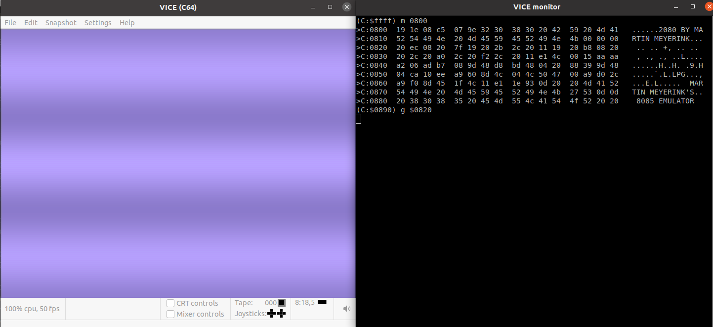
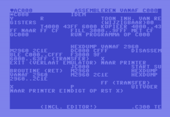
This looks okay: (monitor in vice)
Attaching crt in vice
Maybe one of these problems:
1) you CAN NOT use BASIC routines when a cart is inserted (without weird tricks, i.e.
storing BASIC routines on cart etc)

2) you need to be careful about $01 as you may map in ROM at $8000 without expecting it.

Please refer to this if in doubt:
http://unusedino.de/ec64/technical/aay/c64/memcfg.html

[3] You should also be careful about the usage of KERNAL routines as some of them
sweep across BASIC-code as well!
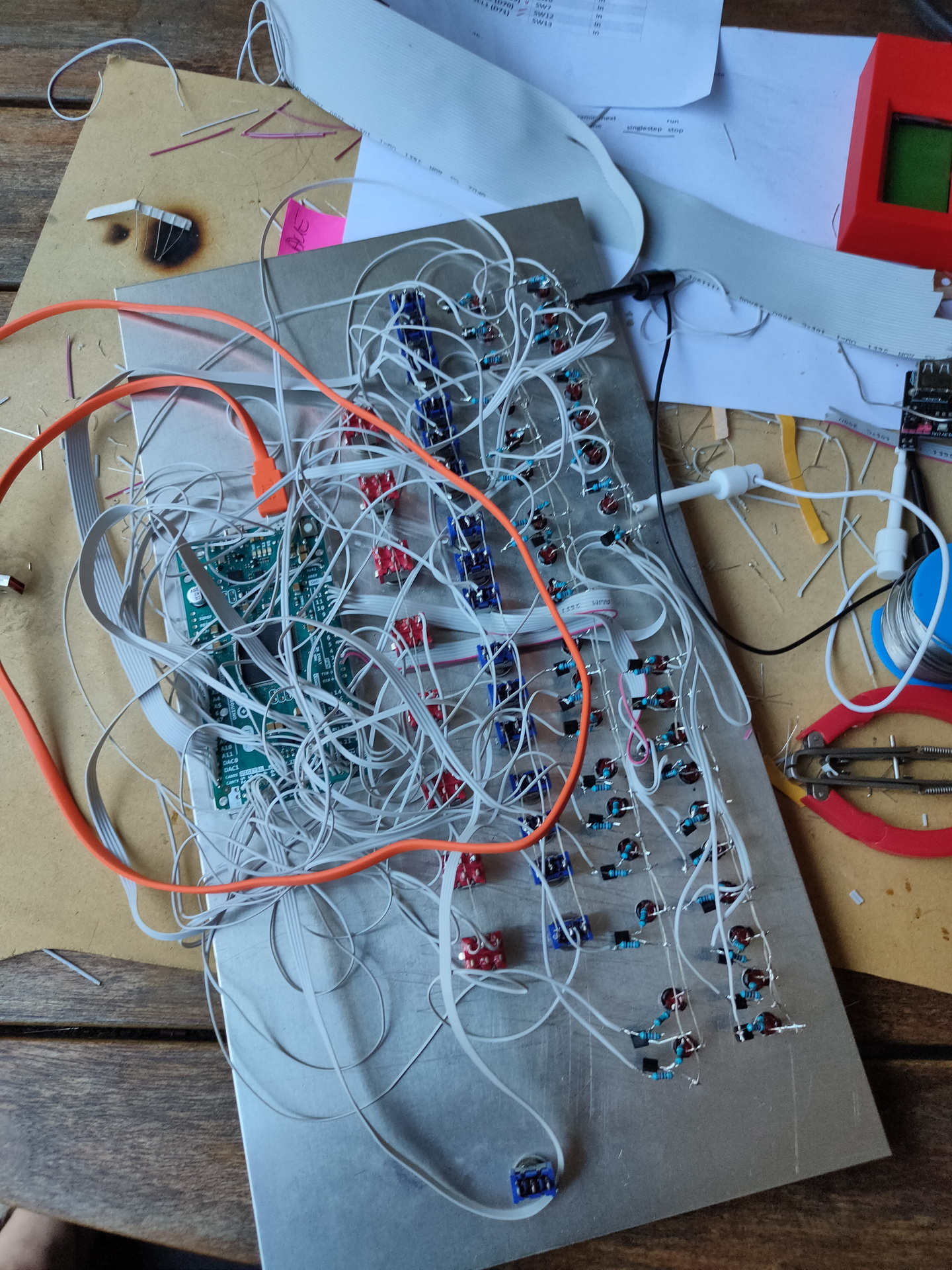
After a whole day soldering yesterday, ending up with a wire mess. Which didn’t work at the end…
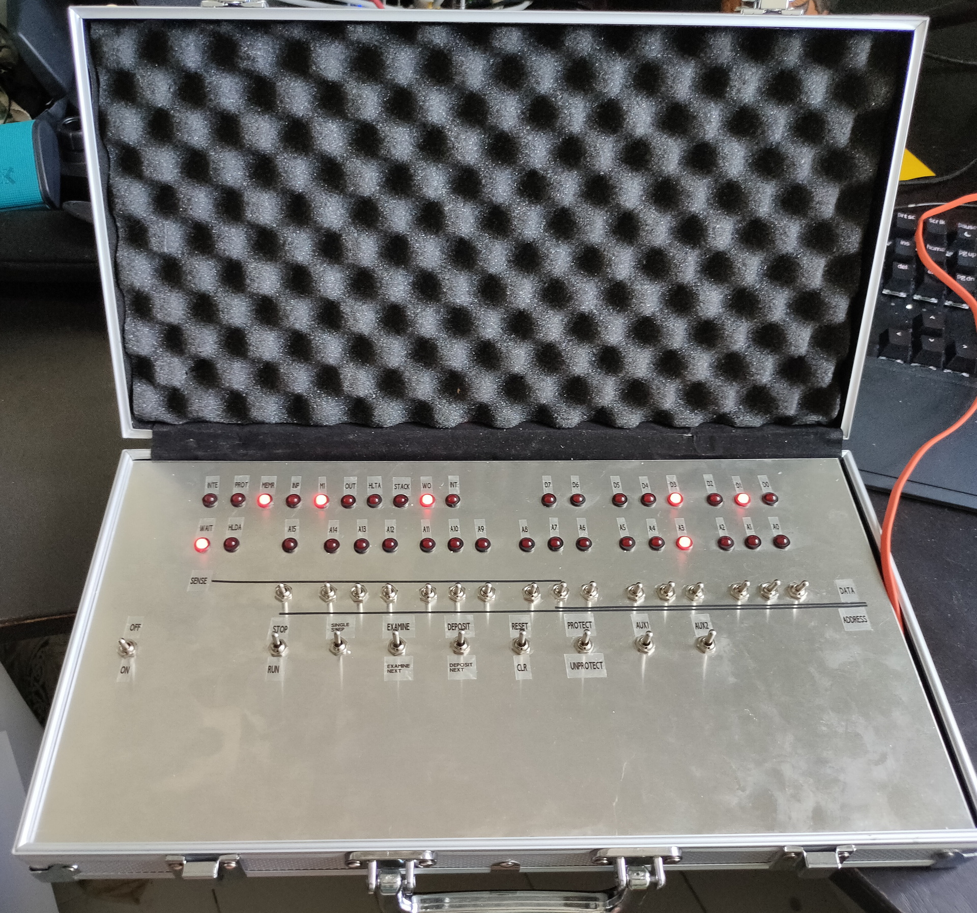
Starting measuring some things, and create some test sketches (led blinky tests) I found out that the main problem was not having the red switches connected to GND. Blue switches where upside down, this was a easy fix. Because these are ON-ON switches, and where already connected to a common line. Then a mixup between D0 and D6 (wires crossed) And it is working! Made some lines and lettering on the frontplate after some playing around.
65c22 connected, new data, and address-bus ribboncables!
First led on Register B blinking!
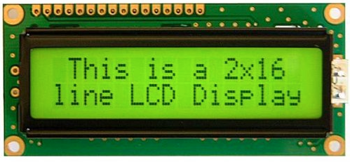
Notes: Temporary display wil be 2×16 Chars. Ram in place, but not connected (is emulated by the Arduino Mega at the moment) Rom is somewhere halfway the atlantic ocean .. still waiting on that one. Ben Eatons clock module is disconnected, i’m using the Arduino as programmable clock right now. (There wil be a little display and a rotary encoder to set clock speed.)
lda #$ff ; all bits
sta $6002 ; set direction (out) for B register
lda #$80 ; set 1 bit
sta $6000 ; set register B
lda #$00 ; reset bit
sta $6000 ; set register B
jmp $8005 ; jmp to bit set part
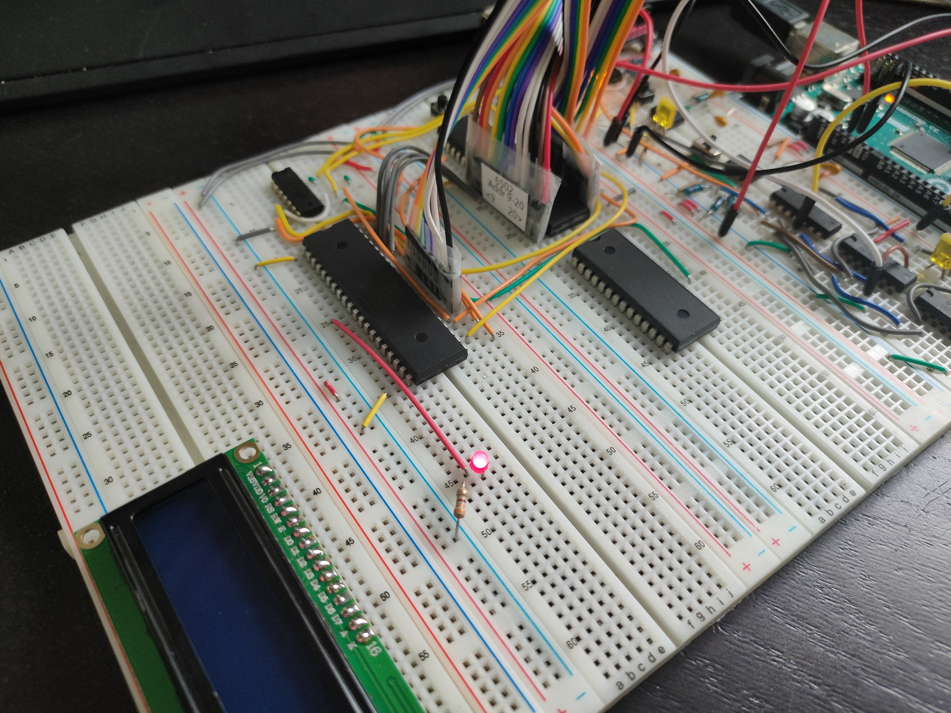
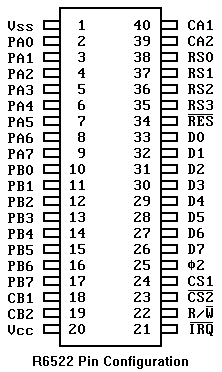
Due to eeproms being scarce, i’m going to use a arduino as Rom emulator. Below is a test setup i’m going to build.
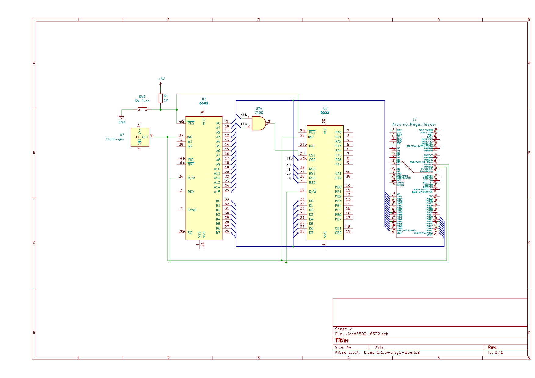
Made the drawing in Kicad.
KiCad is a free software suite for electronic design automation. It facilitates the design and simulation of electronic hardware. It features an integrated environment for schematic capture, PCB layout, manufacturing file viewing, SPICE simulation, and engineering calculation.
Memory assignment:
$8000-FFFF - Rom
$4000-7FFF - Ram ?
$2000-3FFF - Multiple times the 6522 *
$0000-???? - Ram probably

* This is due to the fact i am only using Address lines: 0,1,2,3,13,14,15
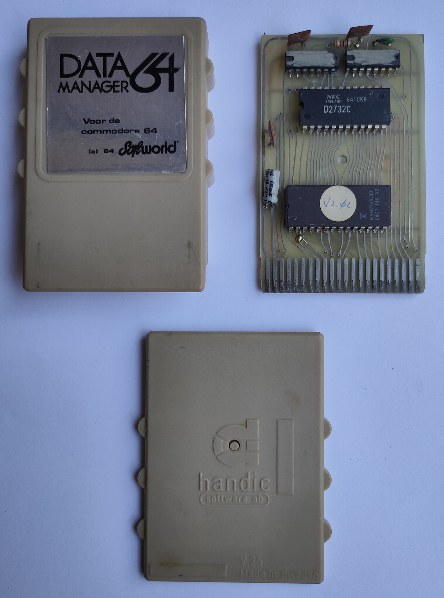
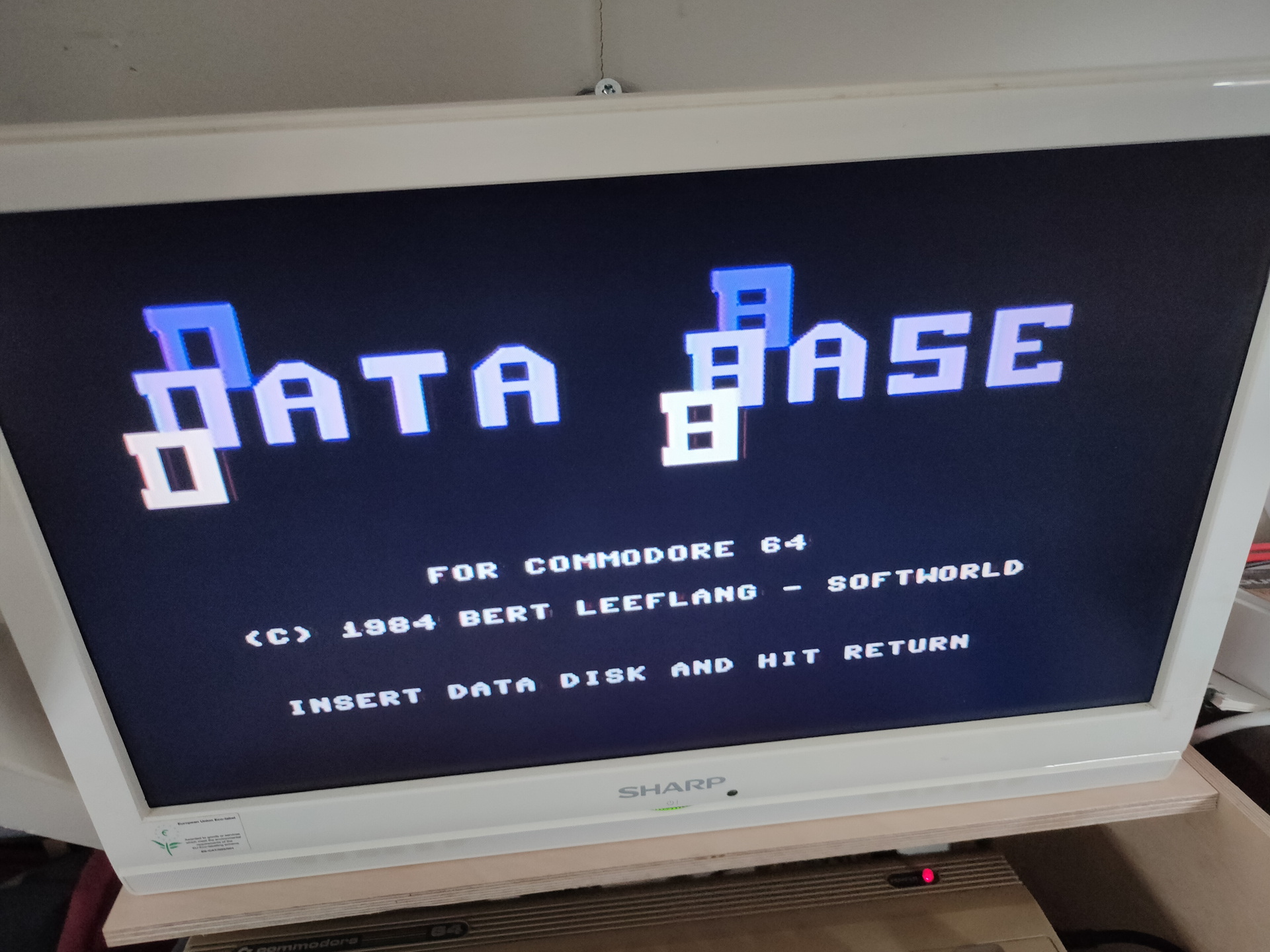
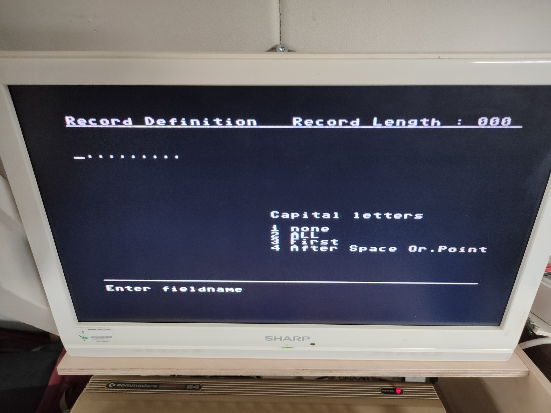
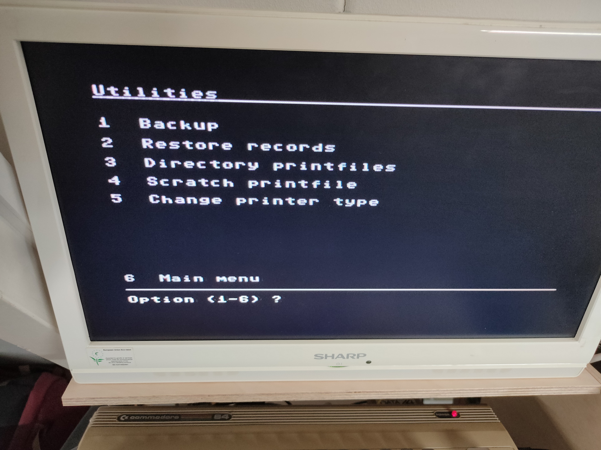
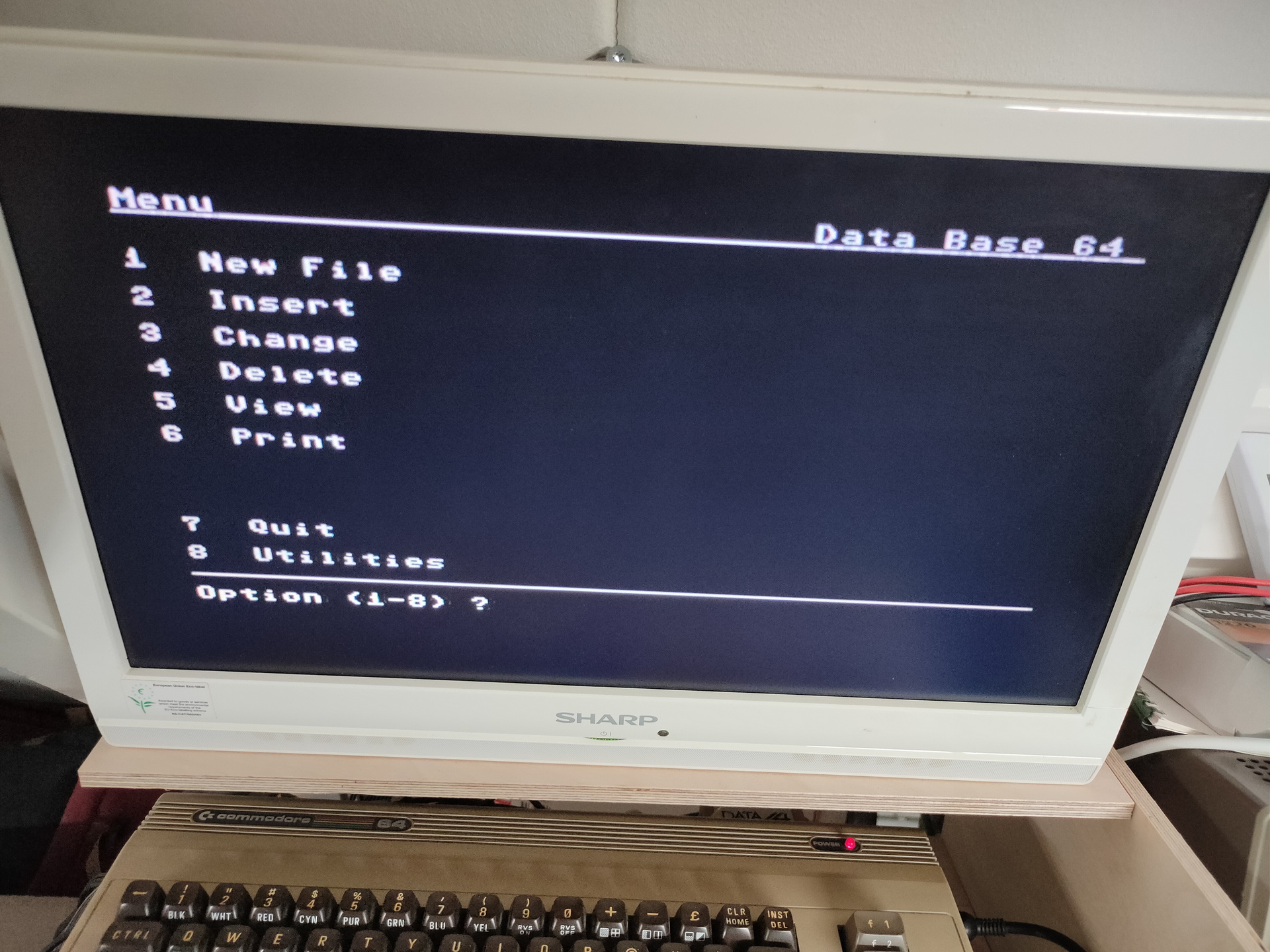
As posted before, i found a cartridge in my collection a while ago. I don’t know where i’ve got this one from.
While searching on the internet for more information, i really couldn’t find anything about it. Not even on collectors sites.
Where did it come from, what does it do?
It says: Data Manager 64 (1984) , Softworld and Handic.
I can find many cartridges by Handic. I’ve checked all database/filers i could find. Non looked like this.
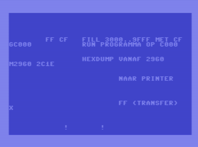
Some screenshots
Next to try .. Dumping the cartridge to file. Probably by changing the way the C64 starts a autostart cartridge. So i have to modify the cartridge port, and put a cross connection on the lines EXROM and GAME, this will change the memory addresses ($8000/$A000) where a cartridge is placed. Then the commodore will start normally, and i can dump the cartrige memory locations to a file.
So pins 8 and 9 have to be switched around. The C64 autostarts a cartridge when it find certain data on $8000
Meanwhile i try to contact some collectors of cartridges.
Next week i’ll be going to May Contain Hackers 2022, what to bring? My old friend Bigred will be there, many others couldn’t make it …
What to bring and do:
Laptops
Arduino touch project?
My new 6502 breadboard computer?
The DVB-T / DAB / FM stick
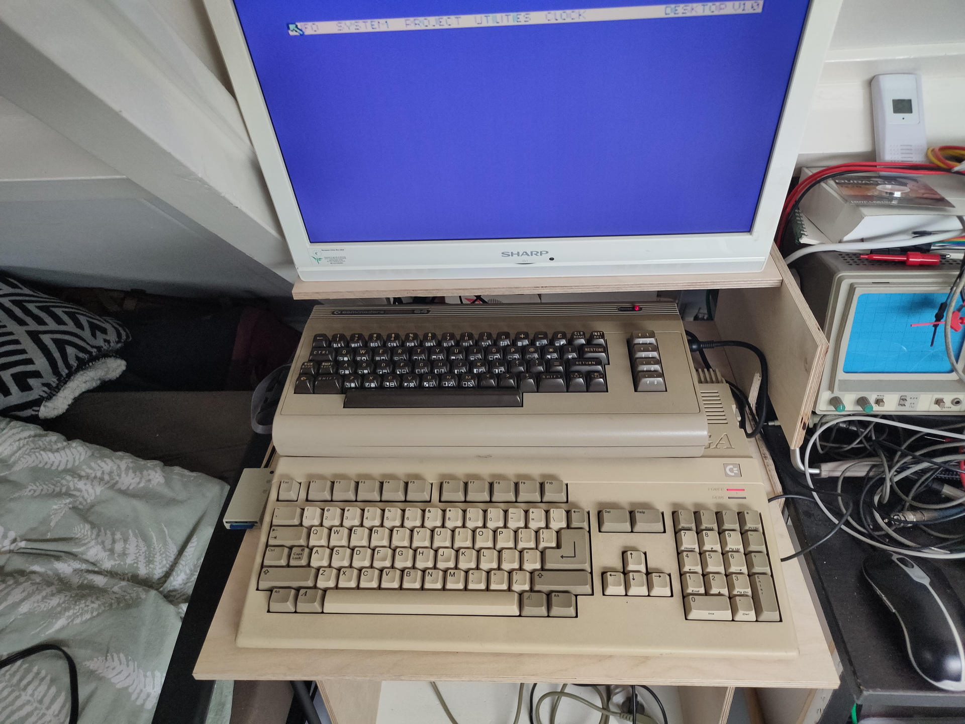
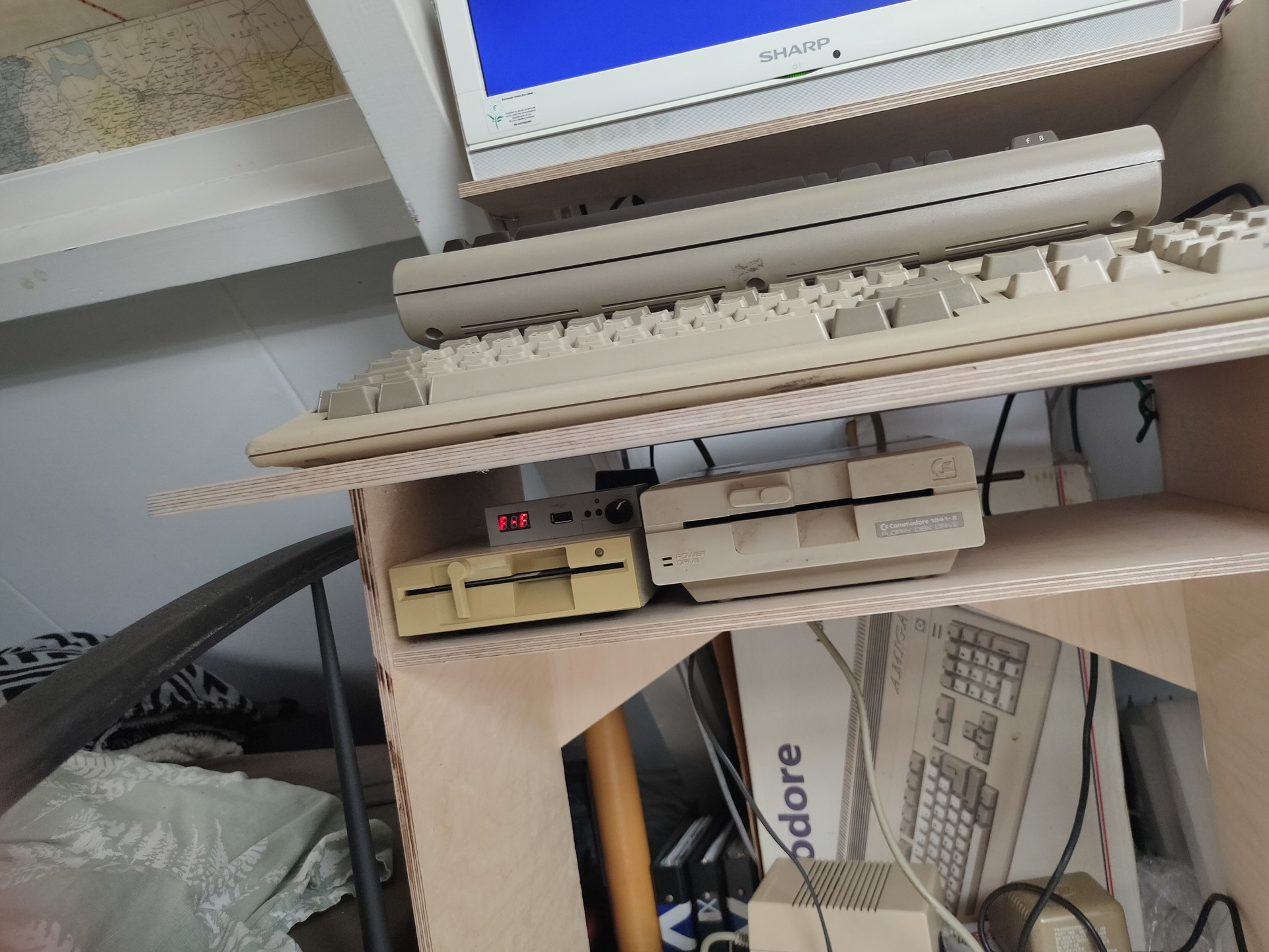
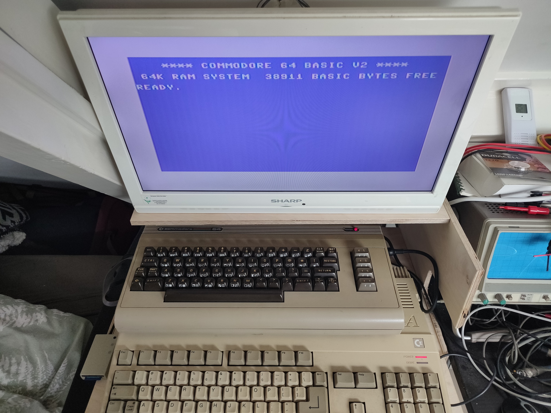
Besides the emulators on my laptop, maybe i’ll bring this little thing (Or a real C64?)
Booting in 4 seconds! Running Vice in 50 or 60 Hz Low latency video! Can emulate cartrides, floppy’s When you connect joysticks or a real C64 keyboard to the GPIO pins it will use that. SID sound using ReSid CRT emulation (look for BMC64 or combian)
I’ve used a basic program on C64 in the past and a Cartridge machinecode monitor in the past. I’ve really forgotten how, what i’ve used and what i’ve done with it. Not nearly as much as my friends at that time. I started with a Vic-20 and played around with machinecode on a 6502. I didn’t have a C64 for many years.
How much funit this!
I’ve recently started to build a 6502 computer again, and programming on 65xx again (Generic 6502 and C64). (2022)
Below is my setup on linux, to write assembly code, compiling and running the code in a emulator.
I have installed the Acme compiler and Vice as a emulator. Both can compile/run machinecode for multiple computer emulations. So maybe i can run my old Vic-20 machine code or the few C64 programs i’ve written.
I’ve only made the bash script, the included asm files i copied from someone on the internet. ( Credit lookup )
makeprg bash file:
#!/bin/bash
set -x
f=""
if [ "$2" == "f" ] ; then f="-fullscreen" ; fi
if [ ! -f $1.asm ] ; then
cp template.asm $1.asm
fi
vi $1.asm
acme --cpu 6510 --format cbm --outfile $1.prg $1.asm
if [ ! $? -eq 0 ] ; then exit 1 ; fi
c1541 -format foo,id d64 $1.d64 -write $1.prg
if [ ! $? -eq 0 ] ; then exit 1 ; fi
x64 $f $1.prg
template.asm
!source "basic-boot.asm"

+start_at $0900

; Set background and border to black
ldx #$00
stx bgcol
stx bocol

; Flicker border and background
.loop
  inc bgcol
  inc bocol
  jmp .loop
basic-boot.asm
; A BASIC booter, encodes `10 SYS <address>`.
; Macroified from http://www.pouet.net/topic.php?which=6541

!source "constants.asm"

!macro start_at .address {
  * = basic
  !byte $0c,$08,$00,$00,$9e
  !if .address >= 10000 { !byte 48 + ((.address / 10000) % 10) }
  !if .address >=  1000 { !byte 48 + ((.address /  1000) % 10) }
  !if .address >=   100 { !byte 48 + ((.address /   100) % 10) }
  !if .address >=    10 { !byte 48 + ((.address /    10) % 10) }
  !byte $30 + (.address % 10), $00, $00, $00
  * = .address
}

; A cooler example is to write
;
;   10 SYS <address>: REM <backspaces>Your comment
;
; When the user types LIST, he will just see
;
;   10 Your comment
;
; but still be able to run it.
; For this, see http://codebase64.org/doku.php?id=base:acme-macro-tu
When running above bash script. it will open the file if it exists, else it will take a template file. After opening it with vi, and editing it, it starts a the compiler and creates a C64 d64 disk. This is going to be autorun/started with the VIce emulator. Appending -f to the bash script will start it in fullscreen mode. ./makeprg myawesomedemo.asm -f
Below it is running without the fullscreen option. but is shows how to start the interactive monitor in vice.
Update: 20220721 .. VIA chip installed Update: 20220801 .. changed layout, addressing and added rom, see below post.
Such a influencial little processor … Apple, Vic-20, C64 (with modifications), PET, BBC Micro, Oric, Atari and Nintendo.
Another (big brother) influencial CPU is the 68000. (Amiga/Atari ST/ Macintosh/Sinclair)
I’ve made a 680x computer in the past, and i want to make another one.
This one will be based on a 6502, because i used to program on this cpu when i got my Vic-20.
Goals of this project:
6502 Cpu
Memory and Rom
Rom must contain a good machinecode monitor
Adjustable clock
Now using Ben Eatons clock diagram, but i will move this to a programmable arduino, with a display which shows the clock rate
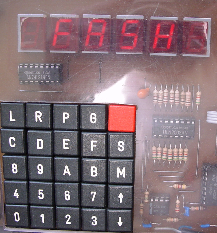
Hex keyboard ro program the machine, just like picture below
Display which was a resolution of at least 640×480
It will be a slow screen, character printing and a gfx mode?
First probably a SPLC780 HD44780, so i can enter/edit machine code.
Hopefully using a SID chip
Hardware monitoring of the address and data lines like movie below
Programming via serial/usb, by halting the 6502 cpu and pushing data into memory or fake-eprom with a arduino
Save/restore by modifying memory
Small
Example of Hex keyboard
Update 20220721
Via chip is on the board. For now i’m using a old display, like this one
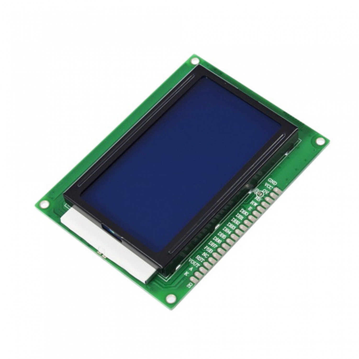
I was planning to use this one
The graphic capable 12864 display (128 x 64 pixels)
I will reuse the schematics i’ve used for the 680x computer. (Posted above)
Update: 20220801
Added ROM, and changed layout. Every breadboard has a function now.
Upper left, Ben’s Clock module (this is going to be changed to a arduino with display which shows frequency) Upper right, power-on reset (Reused part of C64 schematic) Second row left, the 6502 On the right the ROM, RAM i also going to install here. 3rd Row, Address decoding, this is going to be a dynamic setup using dip switches and a eeprom for decoding (i know, this kind of decoding is slow, but i don’t need speed), on the right probably the hex keyboard with its own 6522. 4rd row left, a temporary display 16X2 connected via a 6522. Here i want to have a graphical display. 4rd row right (not started this part yet) a sound device. SID or a Yamaha sound chip i still have.
"If something is worth doing, it's worth overdoing."