I use a bunch of different tools to create video’s or stream stuff. Below is some info about those tools.
Software:
Kdenlive – Linear video editor (Adding text, transitions, etc)
VLC media player – For example to embed video in OBS
OBS – Opensource Broadcast software, i use this also to record my screen – You can use this as a virtual webcam, so you can fool around with the image.
Audacity – For editing audio
QPrompt – Teleprompter
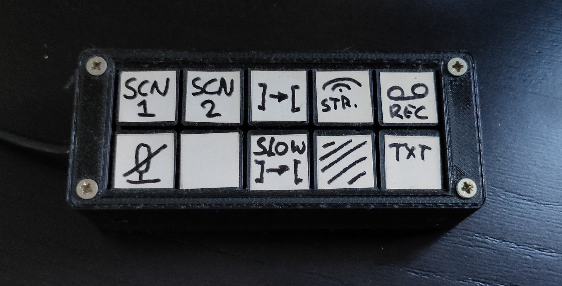
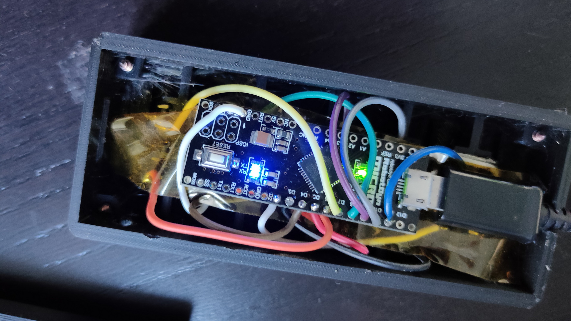
For OBS i made a shortcut/macro keyboard thingy. Based on an arduino pro mini. (Which can connect to a computer acting like a HID, for example a keyboard or mouse) I use this one to emulate keystrokes which i’ve configured in OBS to do:
Switch to scene 1
Switch to scene 2
Transition from scene to scene
Start streaming
Start recording
Mute
[empty] – sometimes used as “start virtual webcam”
Slow transition
Blank screen
Display overlay text
(Originally i planned to do this with a Nextion Display)
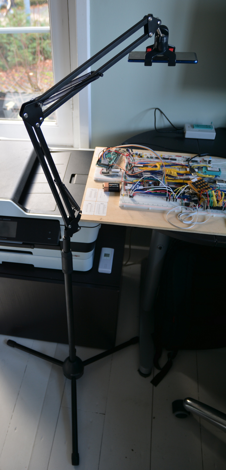
Mobile Phone holder, like a third hand
Sometimes a Nikon on a tripod is better.
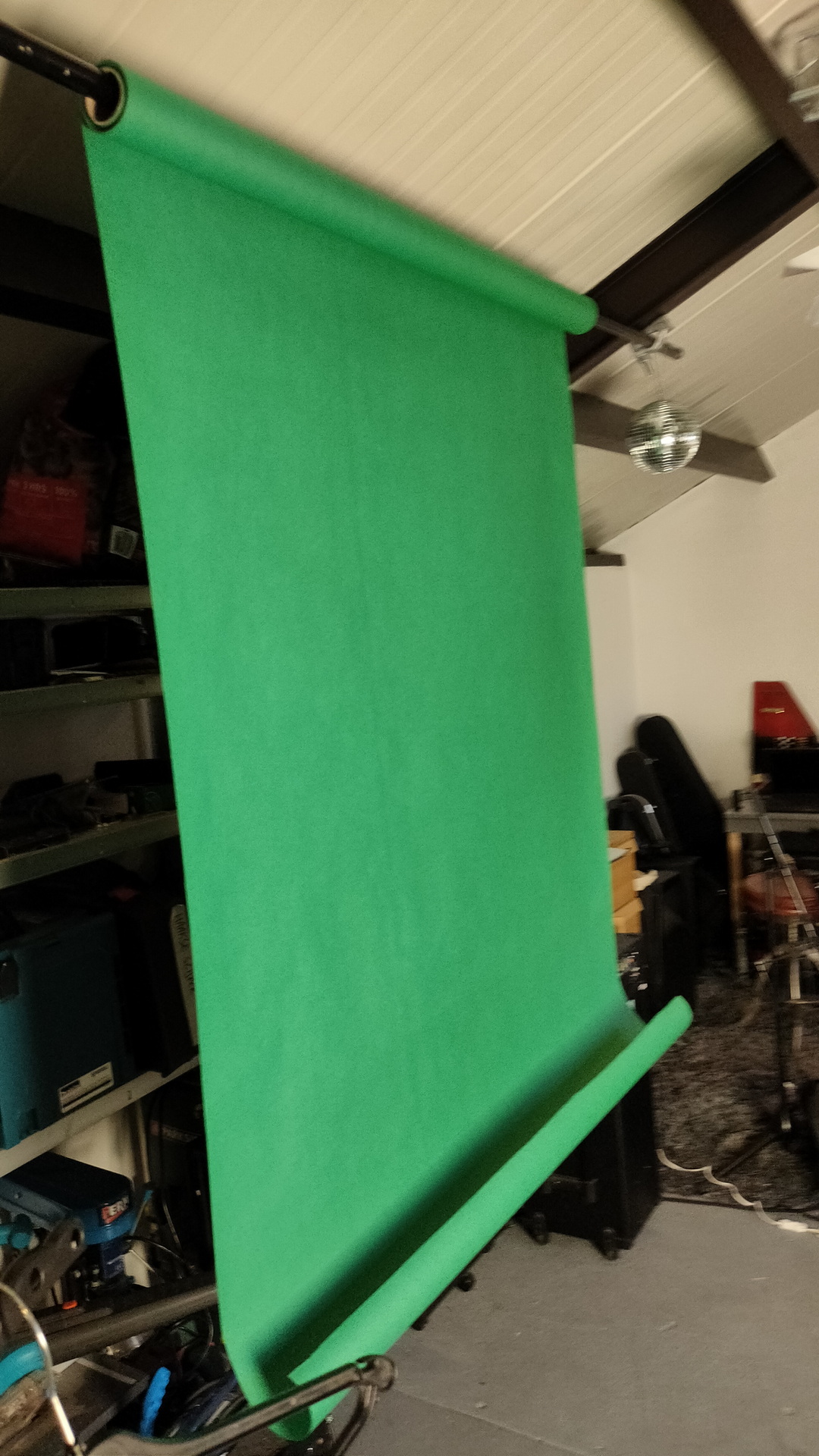
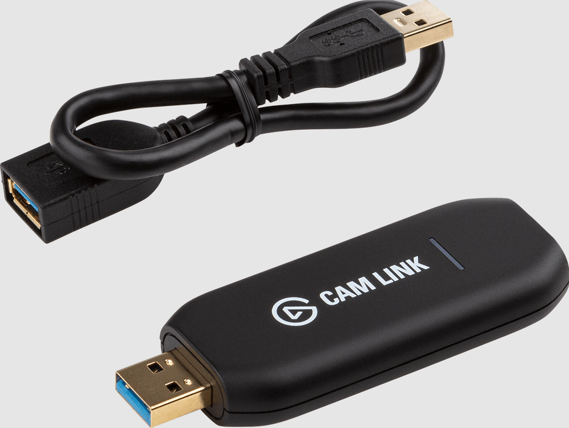
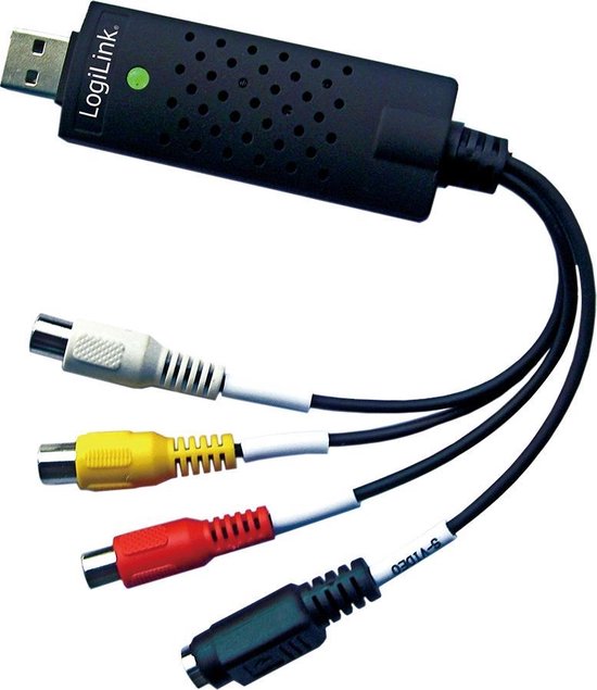
Chromakey / Green screenPortable versionGreen screens .. loads of funVideo grabbers
I don’t have a dedicated webcam for my battlestation. So i mainly use a Actioncam (4k) which can be connected via USB. Or i use a Nikon together with the Camlink.
So i record using my mobile, webcam, screen record Edit using Audacity and Kdenlive.
When recording with OBS i use MP4 as a container, this is a no-brainer to embed in websites. Use mkv when recording long shots, or when connections can break. (A mp4 will be corrupted)
I love to bbq outside, winter, snow/rain whatever. There is no excuse. There are periods where i use a bbq like 3-4 times per week. Sometimes just to get a nice smokey hamburger.
I’ve written this post because sometimes i see (or smell) some rookie mistakes. (Wrong type of smoke, using accelerants)
The tips below are the ones i find useful and are MY opinion, but i’m just an amateur and could be wrong 🙂
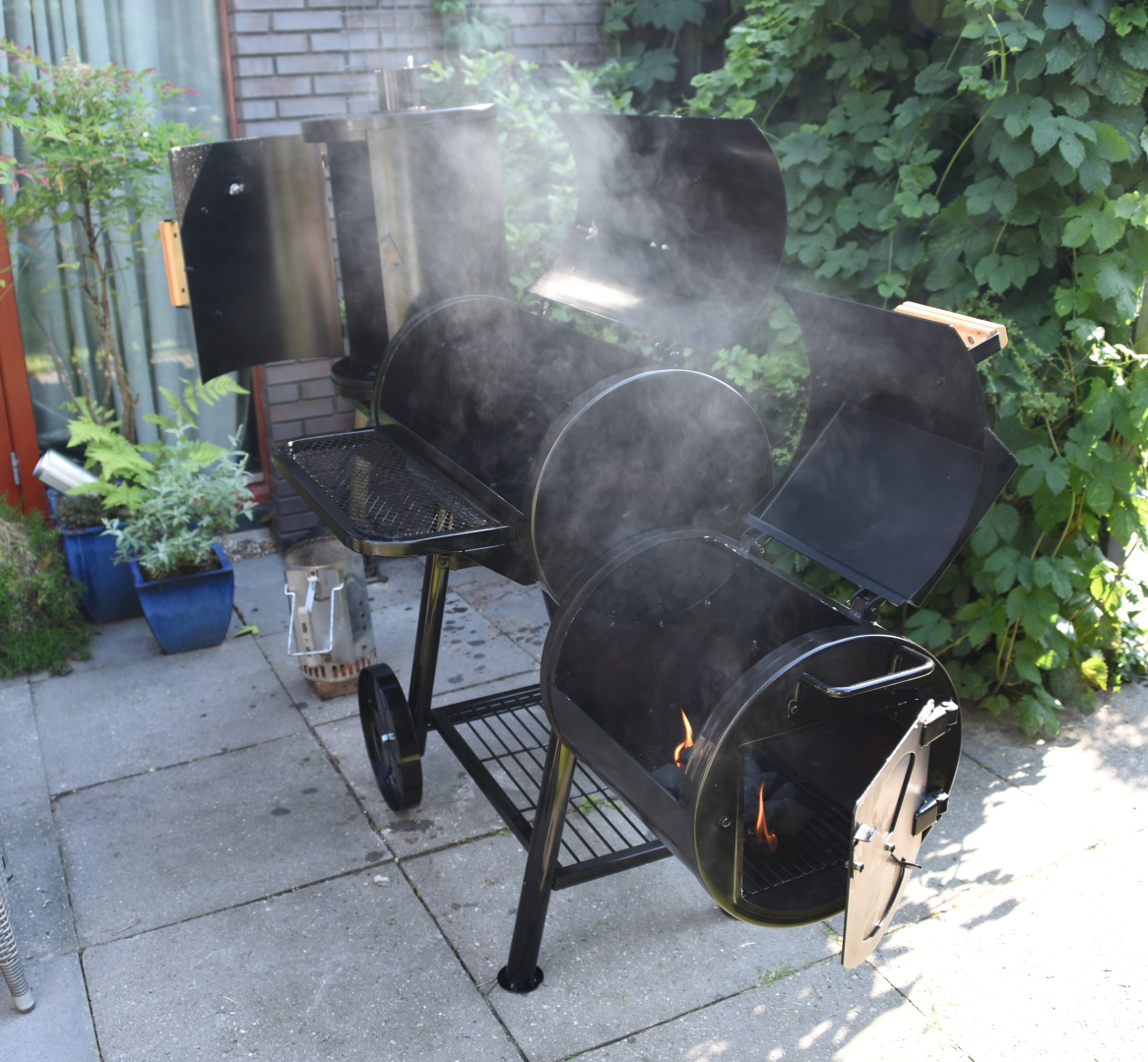
Offset smoker:
Offset smoker with on the left a cold smoke part ( for cheese and fish ) Some hops behind the Smoker
An offset smoker is perfect for ribs, brisket and other meats that are perfect to take some time to absorb smoke and get better when slowly cooked.
When going Low and slow, i follow these rules:
Try to leave the lid closed! No need to let the slowly buildup temperature get away from your meat!
Need to know the temperature? Use the one on your kettle or even better, one with a little cable to leave it outside of the heating chamber. (See tools)
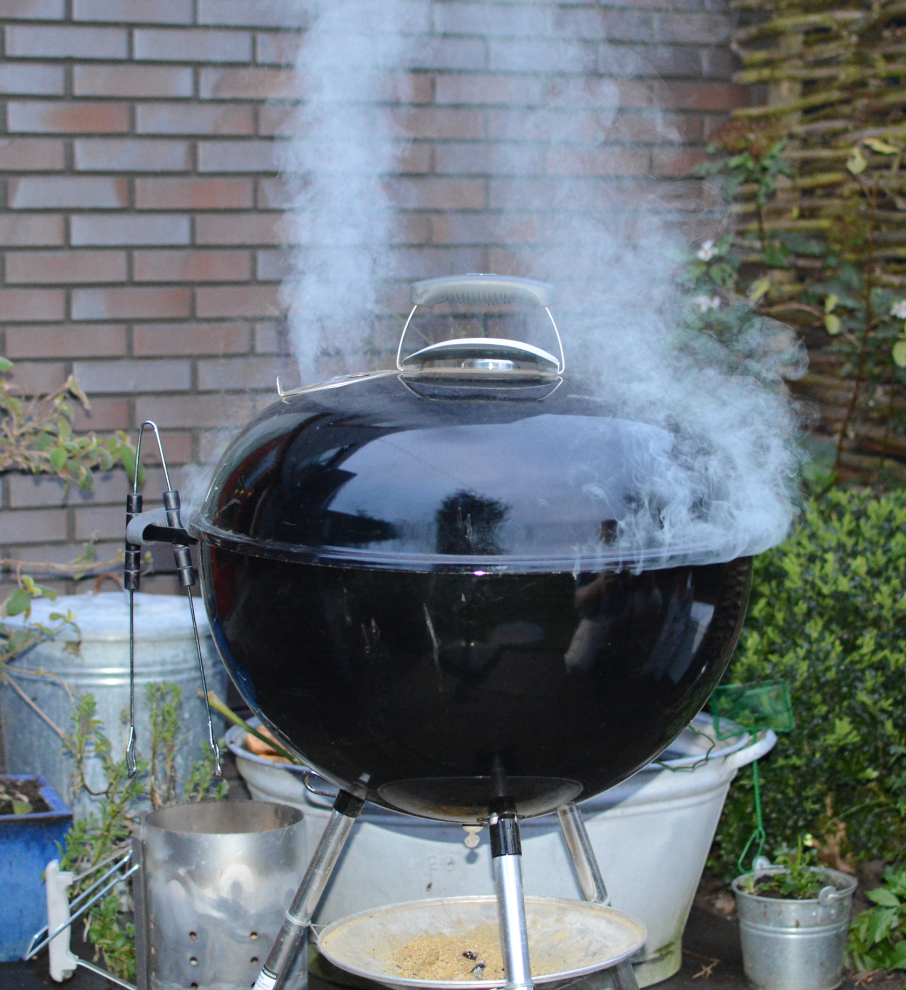
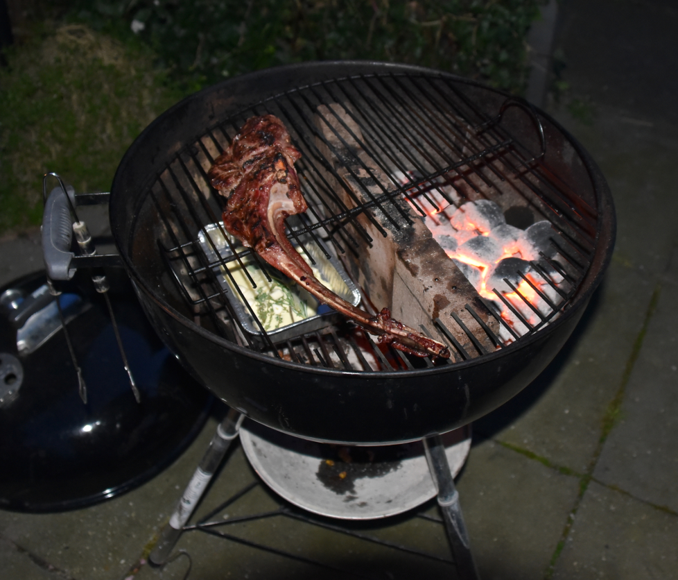
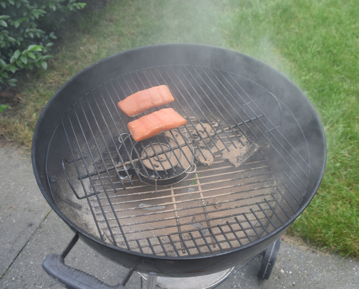
Weber:
I use this one to do a fast steak (below more about this),smoking nuts and pizza.
Use a lid to hold some of the moisture.
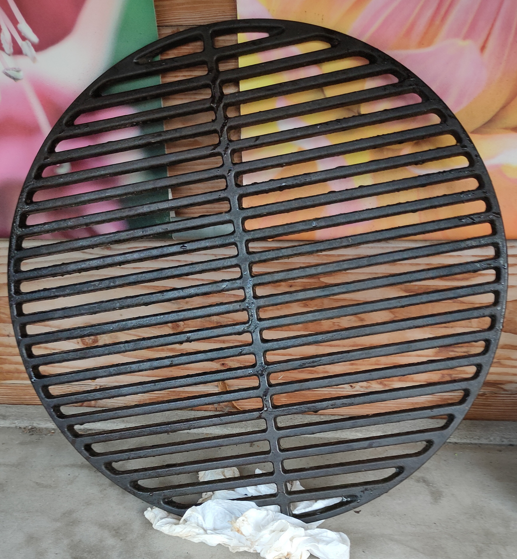
Use a line of bricks though the middle to create a little cold/hot zone. (See pictures)
Buy a second grid/grate with a easy accessible opening. I’ve used an angle grinder to open a part of the grid. This allows easy access to the coals.
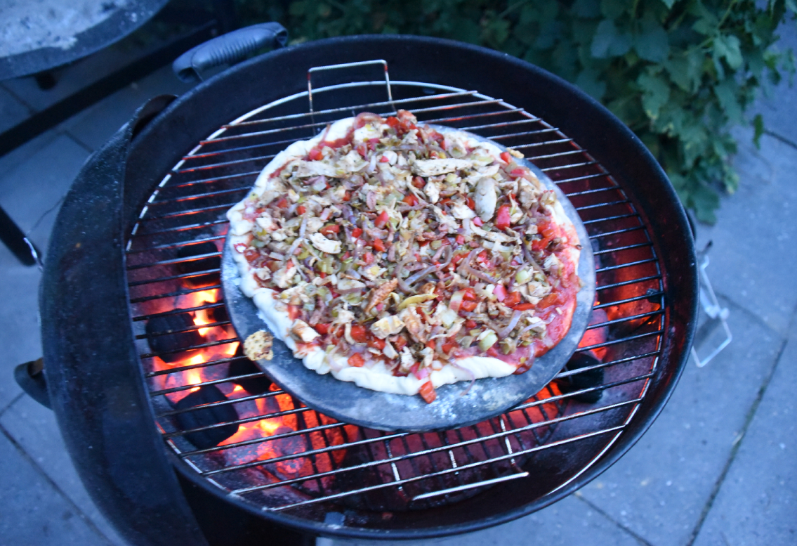
When making pizza, use a stone slate, and lay your coals at the side, in a horseshoe fashion. Some people say .. crank the temperature up to 400 something degrees. Far to high to my liking .. 200 is enough
Tomahawk with a tray below it, brick divider ( indirect / direct part )
Cold smoked salmon using a cold smoke generator (filled with wood dust)
Pizza on a stone slate, i use this slate also for Smoked Chocolate Chip Cookies !
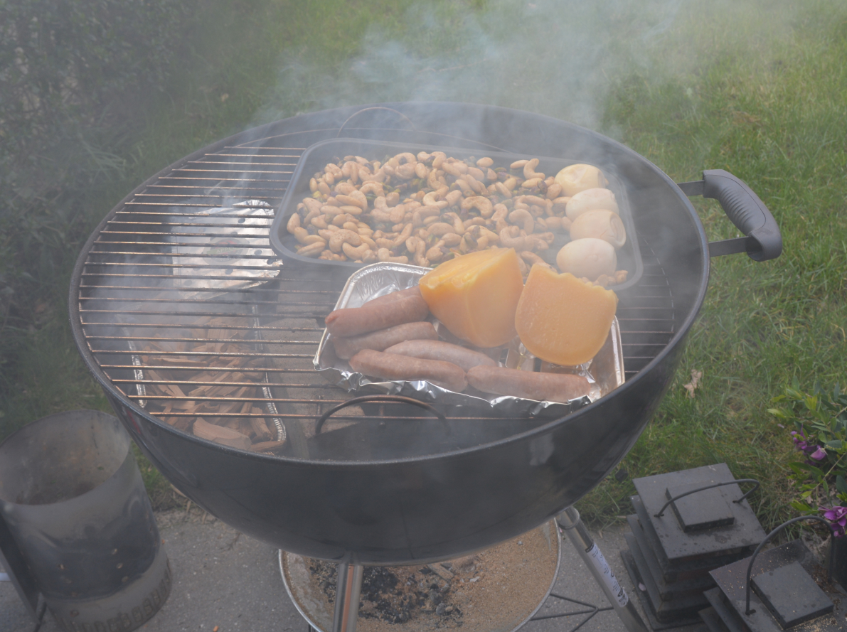
Smoked nuts, cheese sausages and eggs.
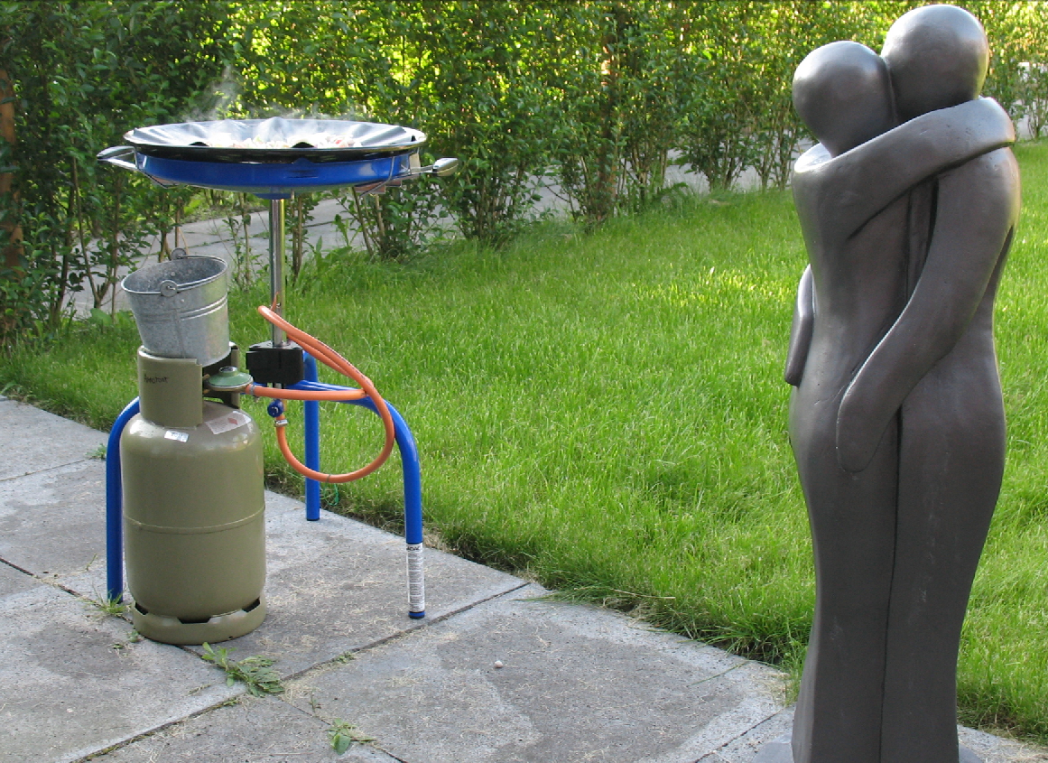
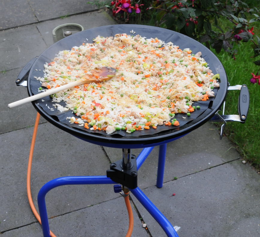
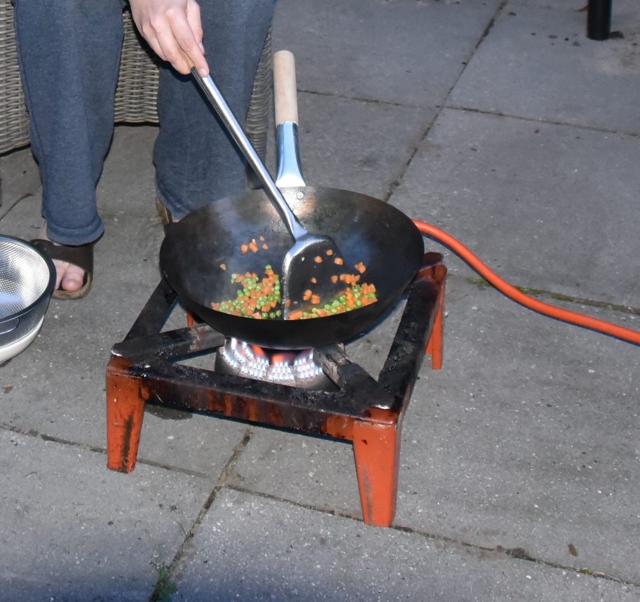
Skottle Braai:
This one is perfect for fried rice, meats/vegetables which need fluids. (Some satay/chinese stirfries or small piece meat like Shawarma.
Another way to stir fry is with our beer brew burner
For all things above:
Prepare everything, get your timing right. Sometimes you are smoking for 6+ hours, but when you forgot to make a marinade, getting things sliced or need a product you dont have/forgot/gone bad .. (i’ve been there)
For the offset smoker .. i don’t use tuning plates .. and probably never will. Tuning plates can be used to get your smoker front to back evenly heated. This is only useful when cooking a lot of meat. I seldom do, so i use the colder part whenever things are going too fast.
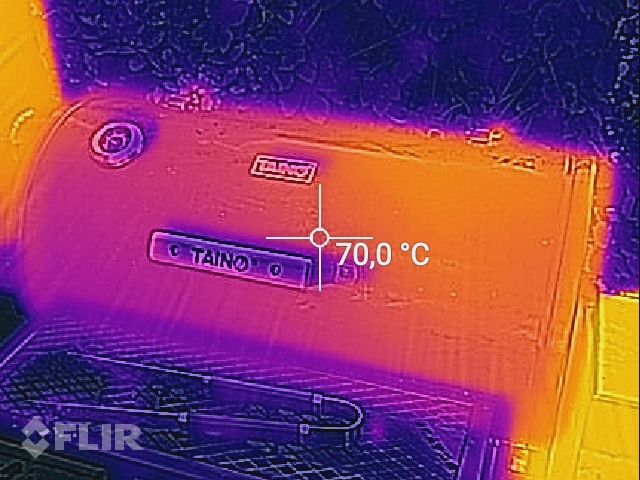
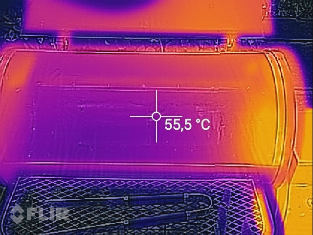
I even used a Flir camera to check the temperature distribution
Using a lot of heat? Don´t put pepper on your meat. It will burn, just wait when it’s on your plate. Salt is fine.
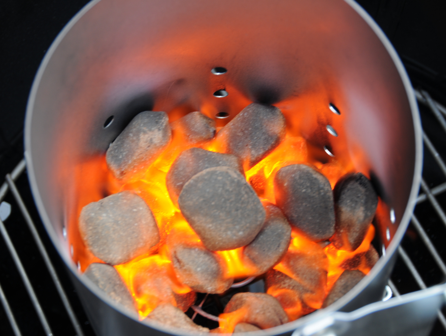
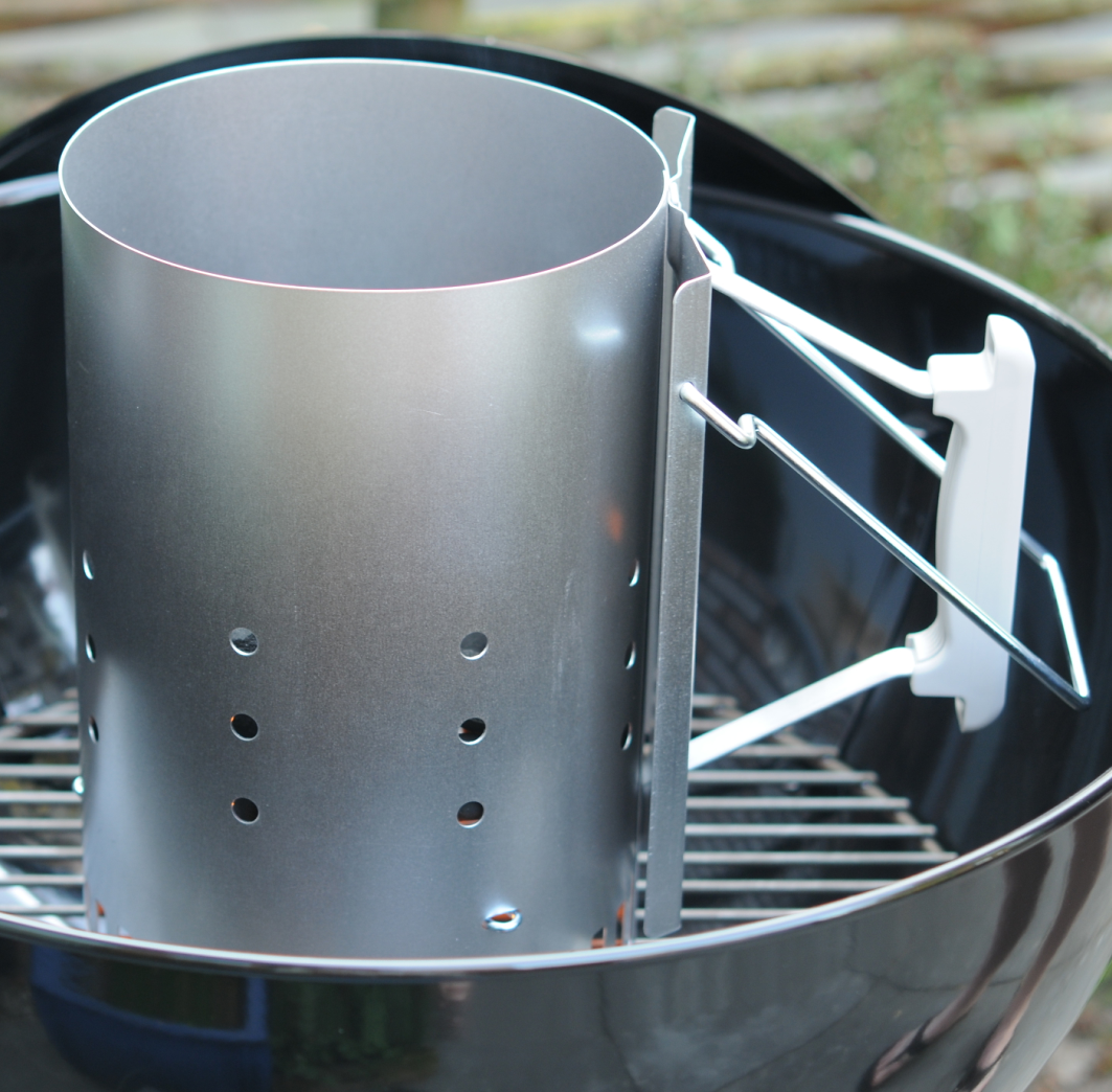
Using briquettes or charcoal? Briquettes, when properly lighted, doesn´t give you a nasty smoke as plain charcoal, charcoal needs more time to burn properly. Briquettes will last for a long time. (See below tools) Coconut briquettes are perfect for slow cooking .. they burn for a long time. Use a chimney and wait until all briquettes are white!
Look at the smoke, it should be thin blue-ish. Not thick or white or even black. Except for smoking woods.
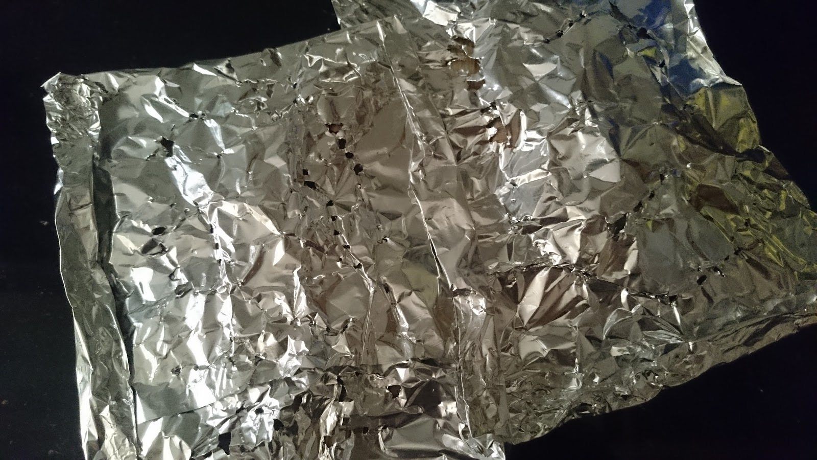
Smoke wood: I’ve tried a lot of smokewoods. Cherry, wine vines, Apple, Pear, hickory, oak, maple and more. Some people and even packages say: “Soak for 30 minutes in water” Well i don’t, then the smoke is mostly water vapor. If you make a neat aluminum foil package with a few little holes, it won’t burst into flames and produces a nice amount of smoke which lasts a while.
Pack tightly and only a few small holes
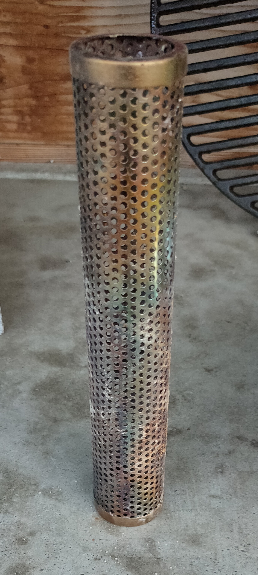
Tube wood chip holder
Don’t use accelerants like spirit. It gives a nasty taste/smell.
Use different plates and tools for raw and cooked meat.
Look at the core temperature, for example for beef
Rare: 50 to 52 degrees
Medium rare: 55 to 58 degrees
Medium: 60 to 63 degrees
Medium Well: 65 to 67 degrees
Well done: 70 to 80 degrees
Stop before it reaches the desired temperature. Wrap in foil and wait a few minutes. The temperature will rise a few degrees
Trying to get your temperature up again by adding briquettes or wood? Sometimes fuel is getting low and temperature is dropping. I seldom but briquettes or wood directly in the fire, it wil give a nasty smoke when it start burning .. I use the chimney to get it burning right. Then i will place it in the offset chamber.
Using a drip bucket? Or want to use more moisture for your meat? Heat some apple juice or plain water, and put this in a container below the meat. (See the tomahawk picture above)
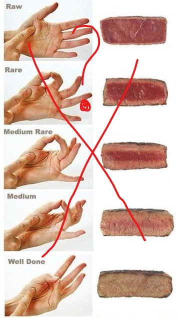
The hand trick to check your meat does not really work. A IT consultant and a bricklayer have different hands, and muscles. 🙂 But it can be an indicator!
Tools:
Spatula, Tongs, Fork, and Basting Brush
Chimney: You need this!
Fast and easy getting your fire ready
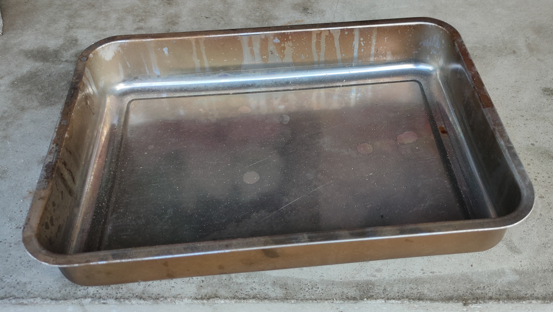
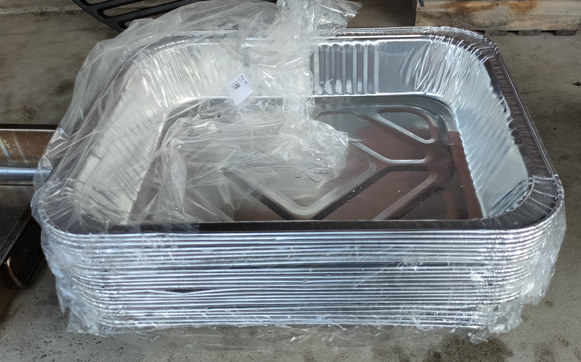
Trays and foils: Use heavy duty aluminum foil.
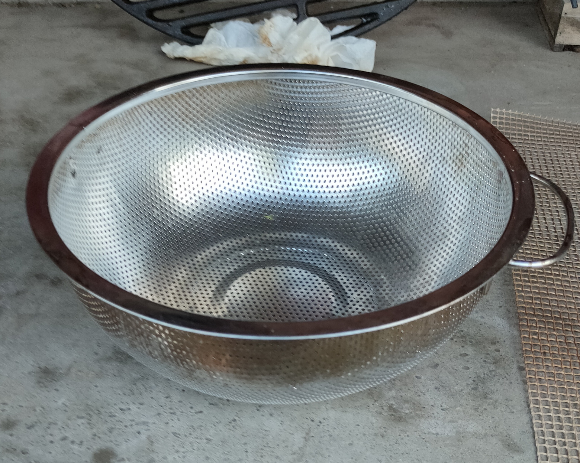
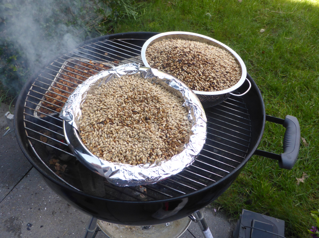
The open one i also used to smoke grains for beer brewing.
Beer grains
Rubs, sauces and spices: Get yourself some nice different rubs and sauces. Make your own rubs (or sauce) I will post some recipes for rubs and the smokey red wine sauce i’ve made. Remember which spices are going to burn in a dry rub. Sauce is not only to complement the meat, but you can also use it to glace the meat while cooking!
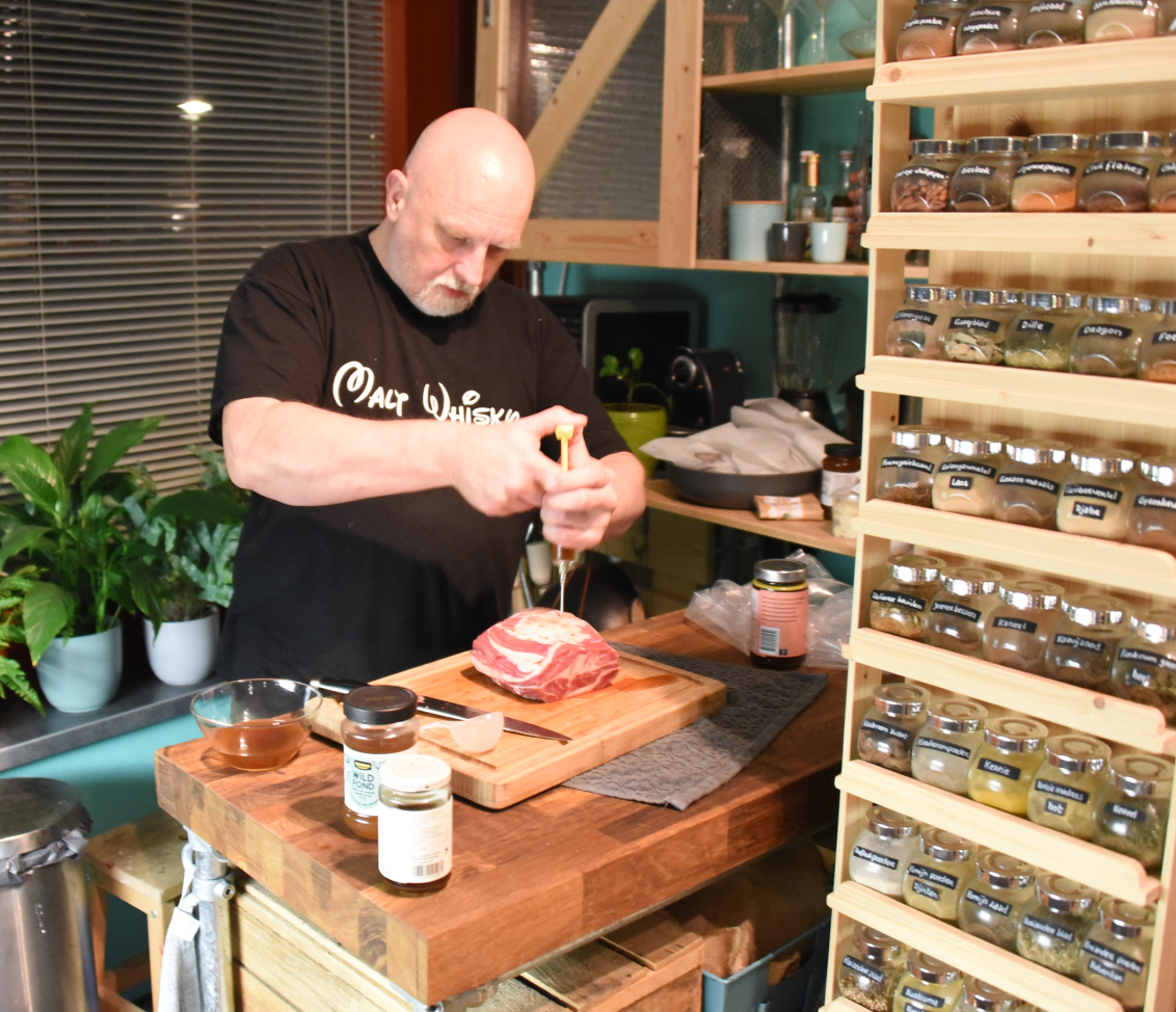
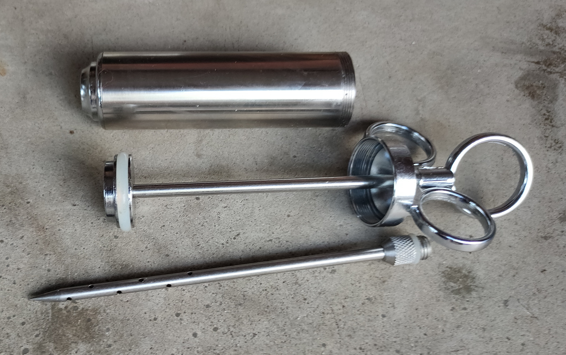
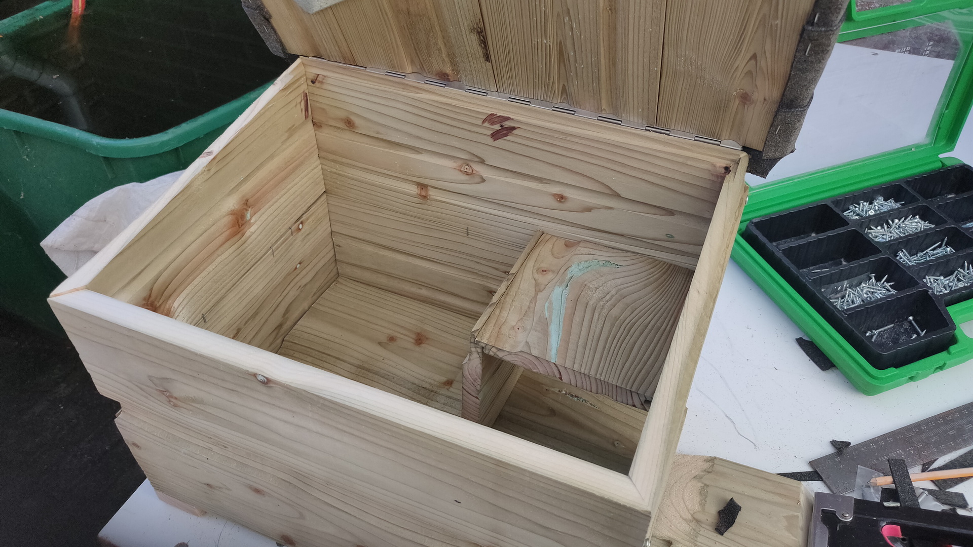
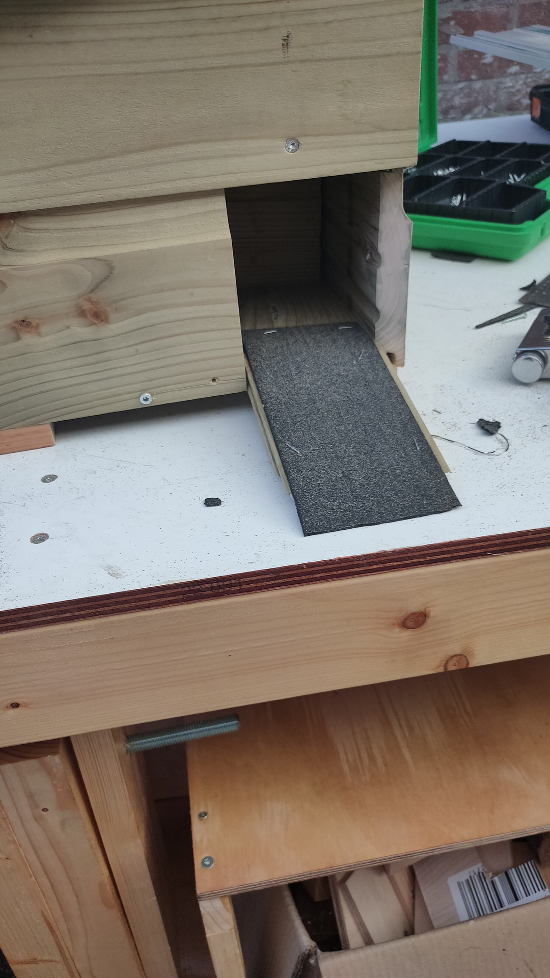
Injecting:
Injecting game stock into meat. Right a spices cabinet i build which can be turned almost 180 degrees.
Injecting meat will give it a nice flavor and tenderness.
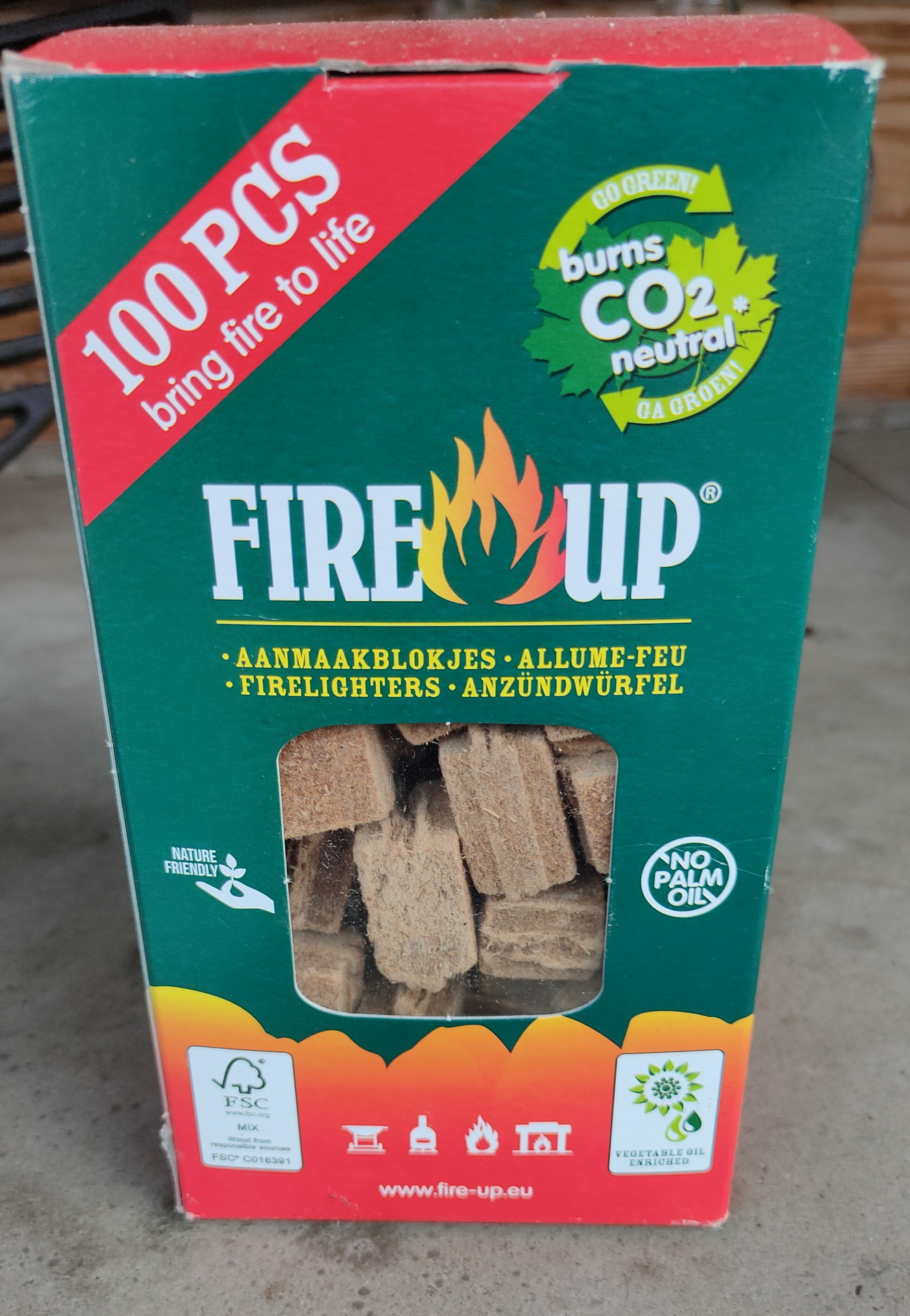
Fire starters:
Use a starter which burns clean .. no smoke no odor
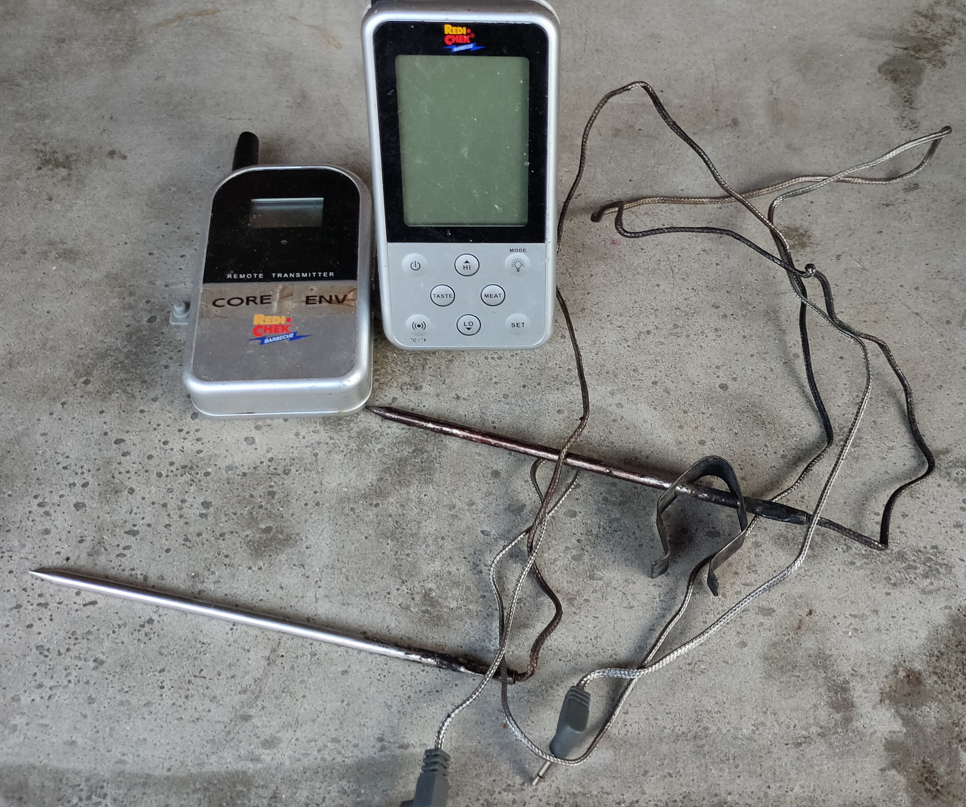
Temperature:
Dual temperature sensor
Use a wireless dual temperature sensor, one for the meat (core) and one for the temperature in the Bbq.
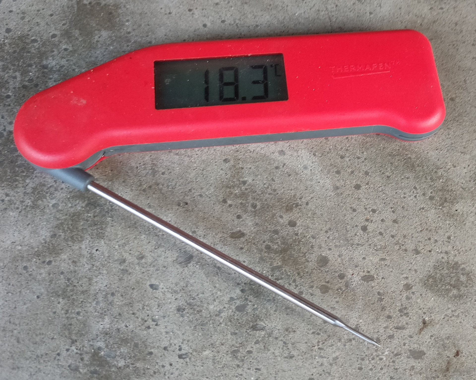
For a fast reading, for example in ribs, i use below speed sensor
Reads temperature in 2 seconds
Use pin for testing tenderness
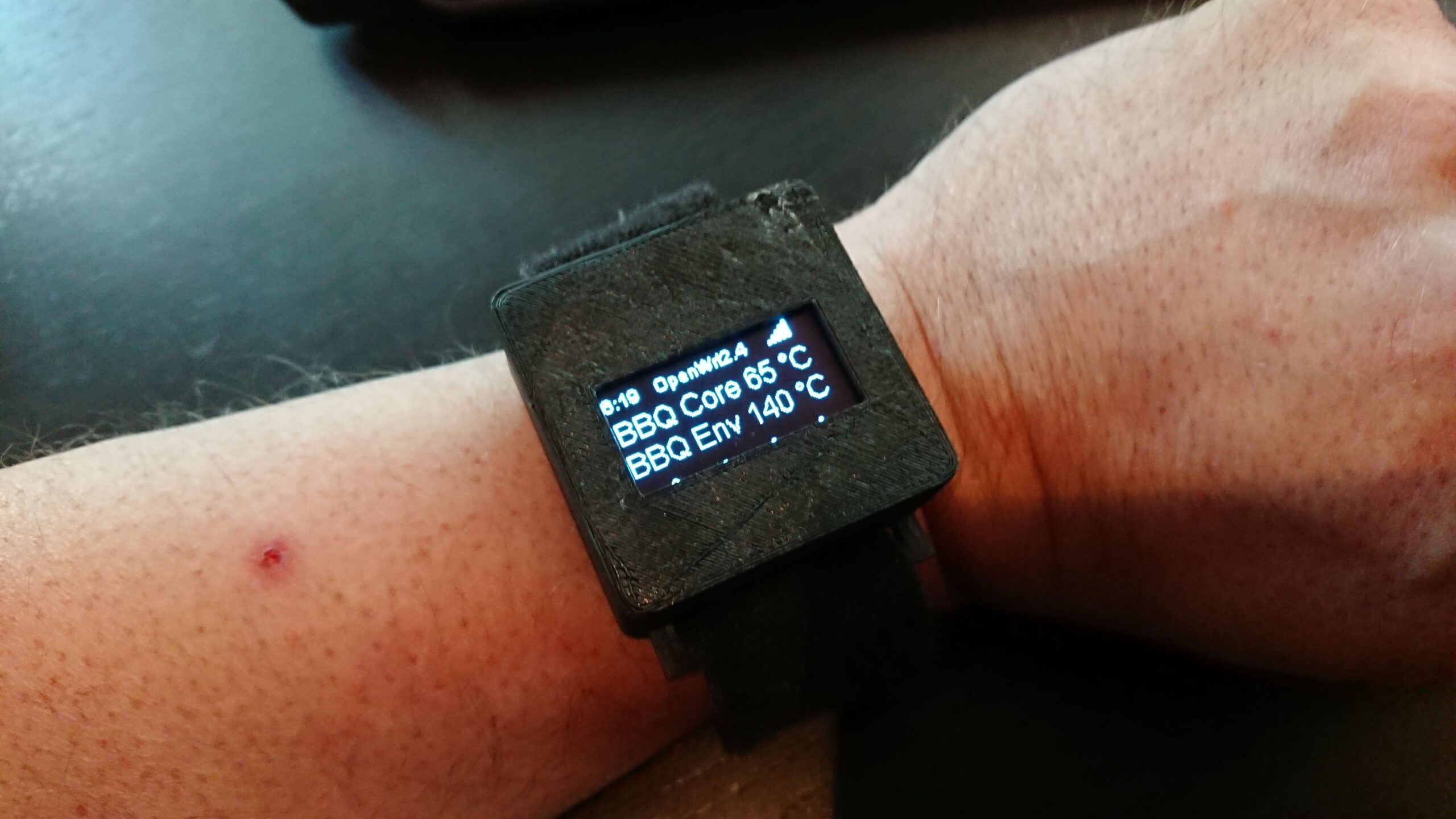
Or … going fancy with my own build bbq watch .. (separate post)
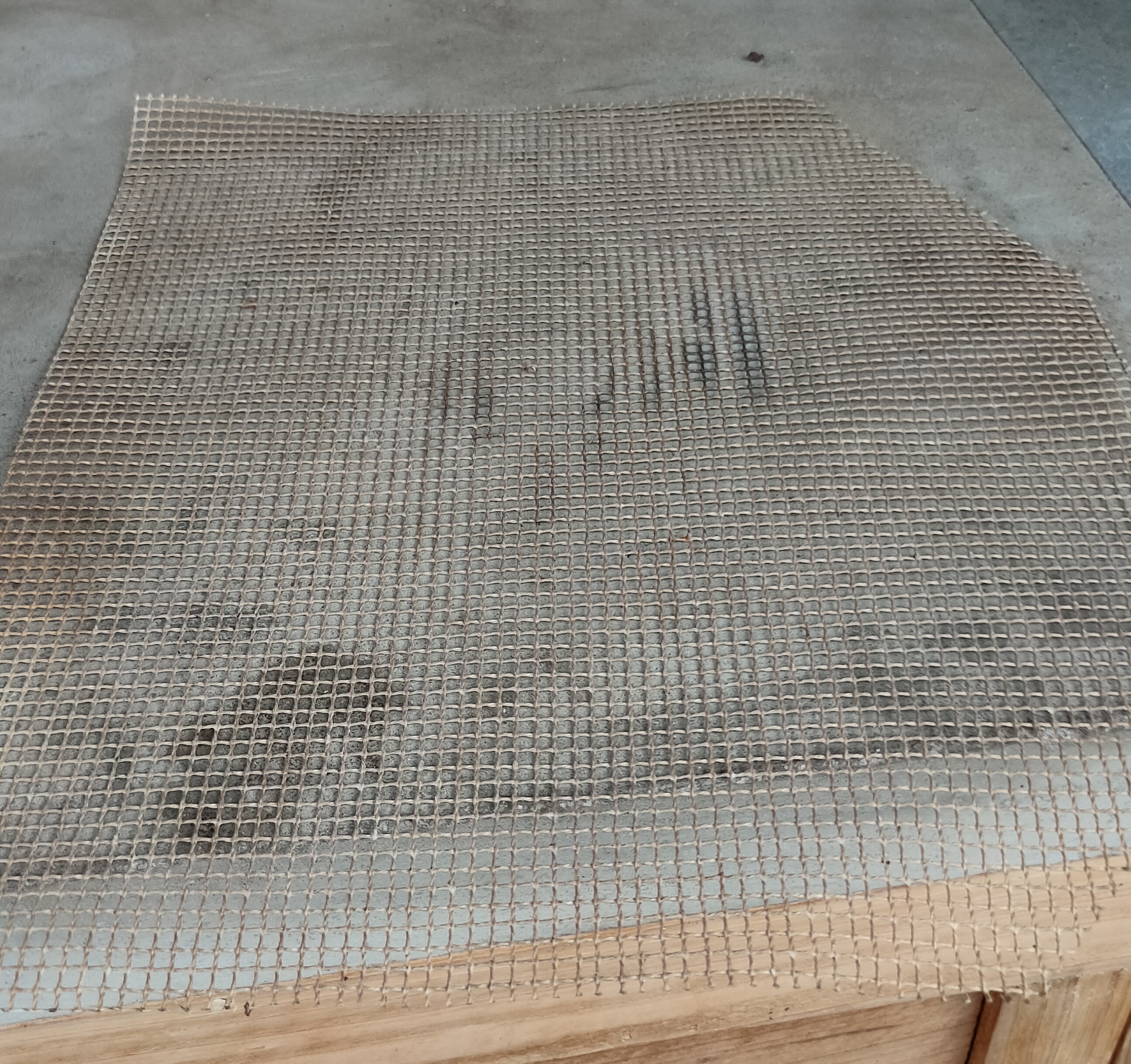
Small pieces of meat? Use a fine mazed mat like this
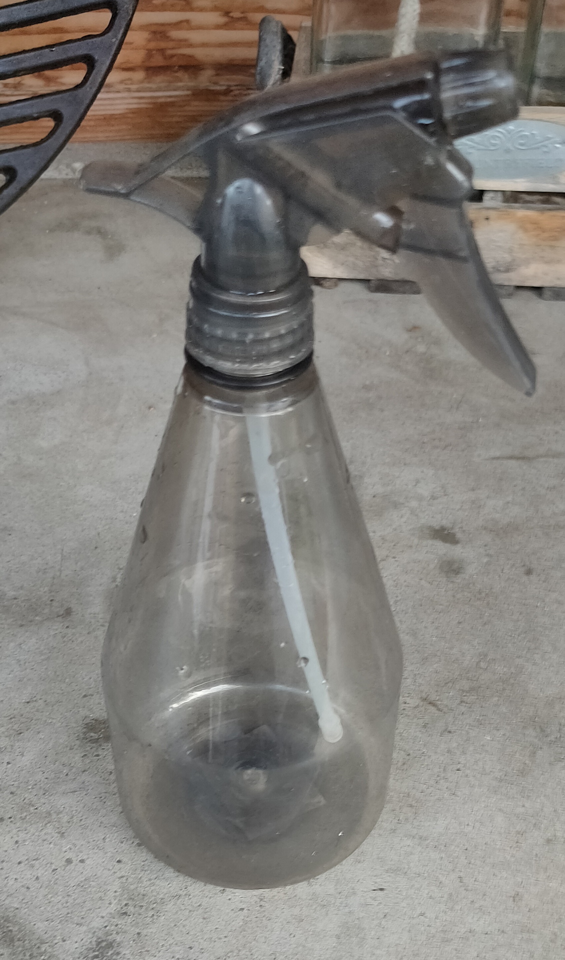
To moisturize your meat or apply seasoning like apple juice, use a plant spay
At last .. some tips for you to try:
(No links to recipes on the internet, just google there are many .. i will post recipes i’ve tried myself)
Ribs 3-2-1 method
Got a nice steak with a fat cap? Try argentina style. Just do a 3-minutes per site. (Even better .. use a pre-heated iron cast grate to get some nice lines. At the end press the meat on the grate, so the fat melts and drips onto the coals. These wil burn and give big flames. Those burning flaming fat wil give your beef a taste to remember!
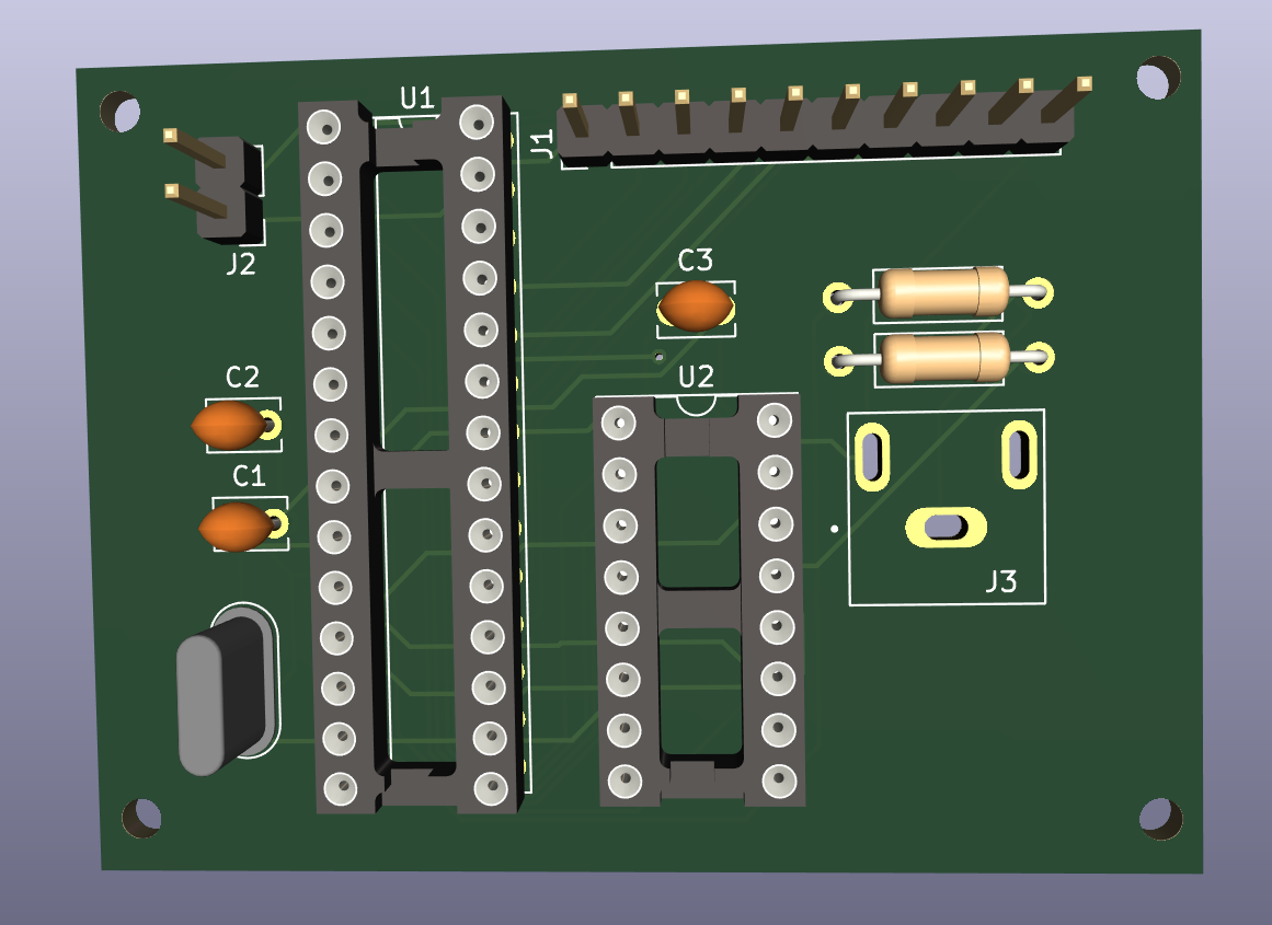
Composite video print designed and ordered from china.
Changed some vlans in my network. I need to think of a way to extract/migrate domoticz 433 info into a new instance. For example .. i’ve got some instances in my device list which are only being controlled by domoticz, there is no remote i can reuse.
Tried welding again, because i could not do it for a long time, i noticed i have to practice again after 2 years. (I’ve got a dedicated power outlet outside now .. 🙂
Last 8mm films work done. (Converted all of my dad’s old 8mm reels)
Designed a hidden remote cabinet, holding remotes out of sight for the occasions when automation doesn’t work.
Designed also a wooden wall with hidden cabinets in our bedroom.
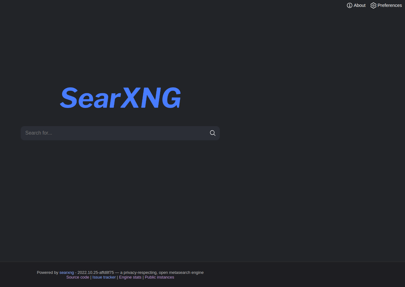
Searx is a free and open-source metasearch engine, available under the GNU Affero General Public License version 3, with the aim of protecting the privacy of its users. To this end, Searx does not share users’ IP addresses or search history with the search engines from which it gathers results.
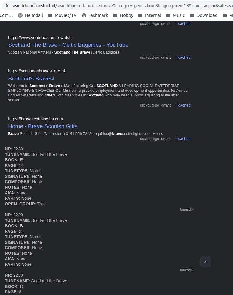
It’s easy to install using docker, but i wanted to add my own mysql server data. ( pipetune search engine data in below example ) There are many search plugins and quite hackable. But there was a missing python module in a docker image.
ModuleNotFoundError: No module named ‘mysql’
So i build a new docker image based on the original
# Install docker and docker-compose

cd /usr/local
git clone https://github.com/searxng/searxng-docker.git
cd searxng-docker
Edit the .env file to set the hostname
Generate the secret key sed -i "s|ultrasecretkey|$(openssl rand -hex 32)|g" searxng/settings.yml
Edit the searxng/settings.yml file according to your need
Check everything is working: docker-compose up
Run SearXNG in the background: docker-compose up -d
I’ve changed the docker-compose.yaml
Changed
<     image: searxng/searxng:latest

into
>     build: .

And
changed the listen address
<      - "127.0.0.1:8080:8080"
into
>      - "8080:8080"
Created a Dockerfile
FROM searxng/searxng:latest
RUN pip install mysql-connector-python
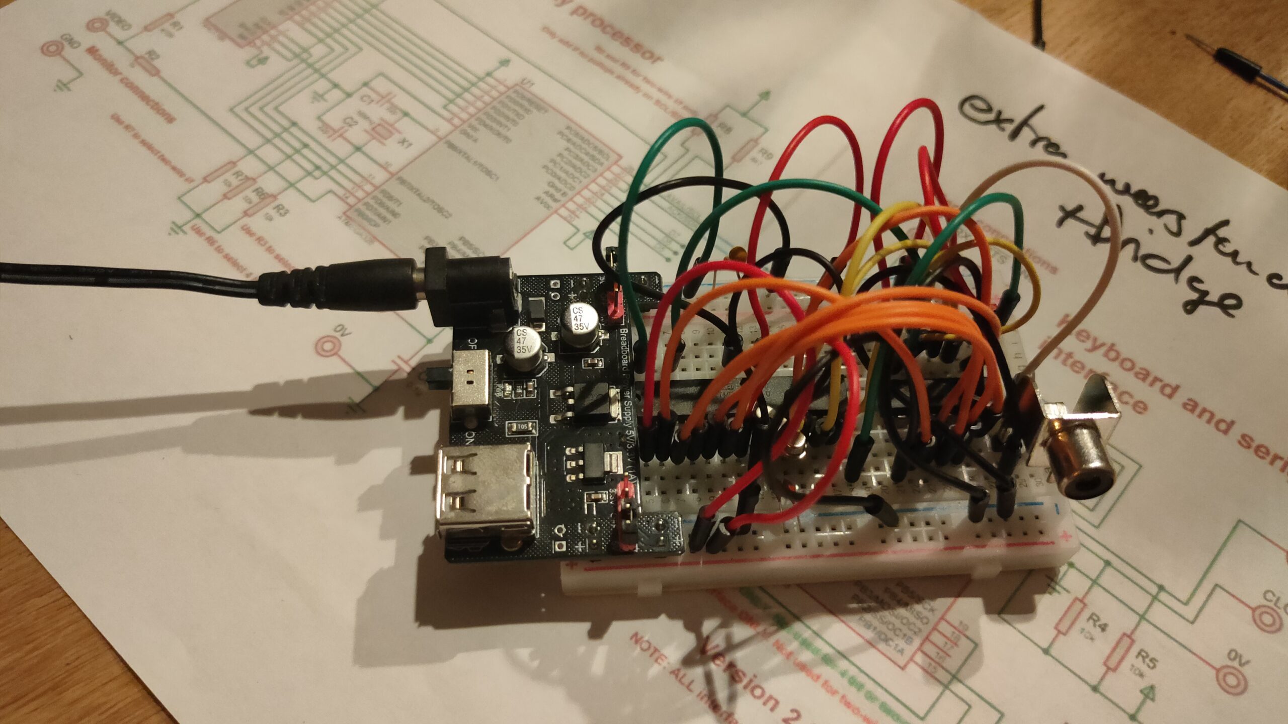
I started to get some composite video generated with a arduino for my 6502 project.
UPDATE: 20221021
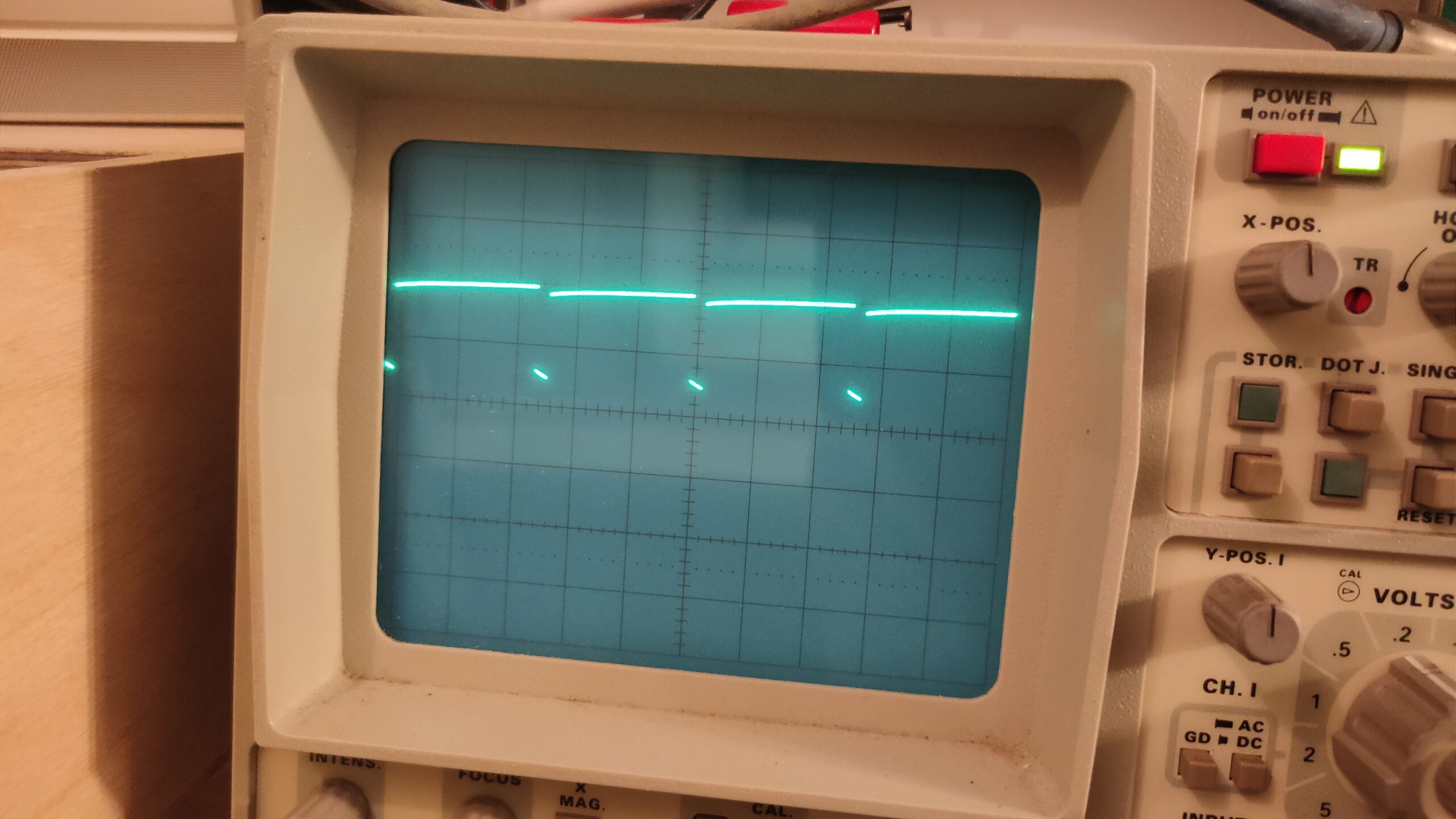
It is based on Grant Searle’s design, and yesterday I had some signals on my scope which looked like a screen with a character. But my monitor would not recognize a usable signal.
Today I tried a second version and another set of chips and crystals.
It looks like a signal, but I can’t see a clock pulse from the crystal?! So .. how?
Maybe I used a bad power supply. And killed something?
UPDATE: 20221021
After switching to another power supply, and checking the atmega328p fuses again (also wrong) .. at least SOME success!
Still a little sync problem, but i’ve got a blinking cursor!
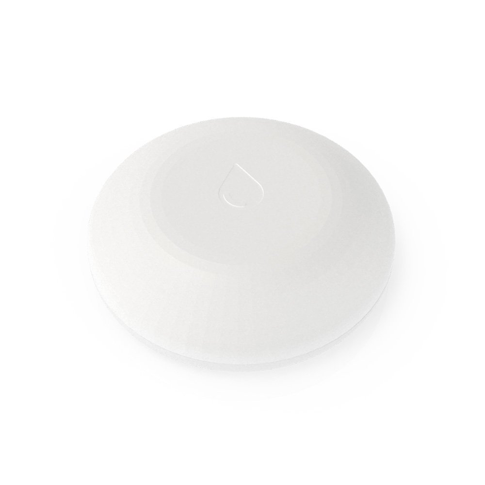
I’ve had this Shelly sensor for a long time. But never posted anything about this. Last weekend we had a -situation- in our kitchen, so what better time to test this device again!
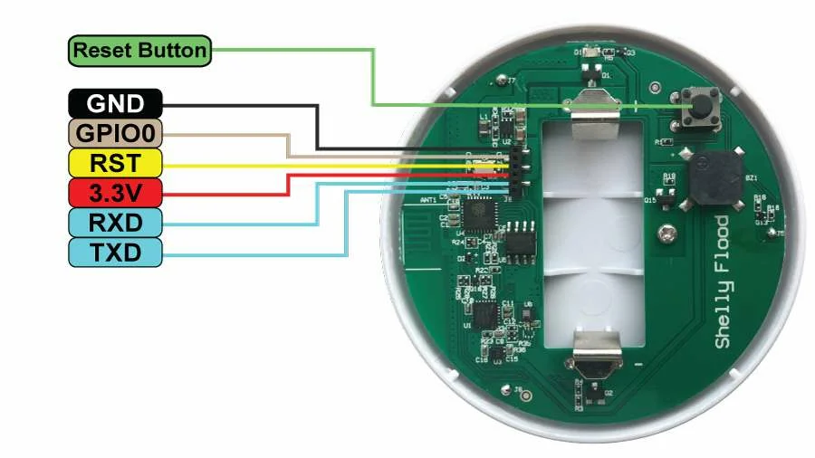
This little disc shaped device has three metal points on its bottom side, those are the flood (water) sensors. It stay’s in sleep mode when all’s good. It does several things when it detects water.
Emits a alarm signal
Wakes-up wifi
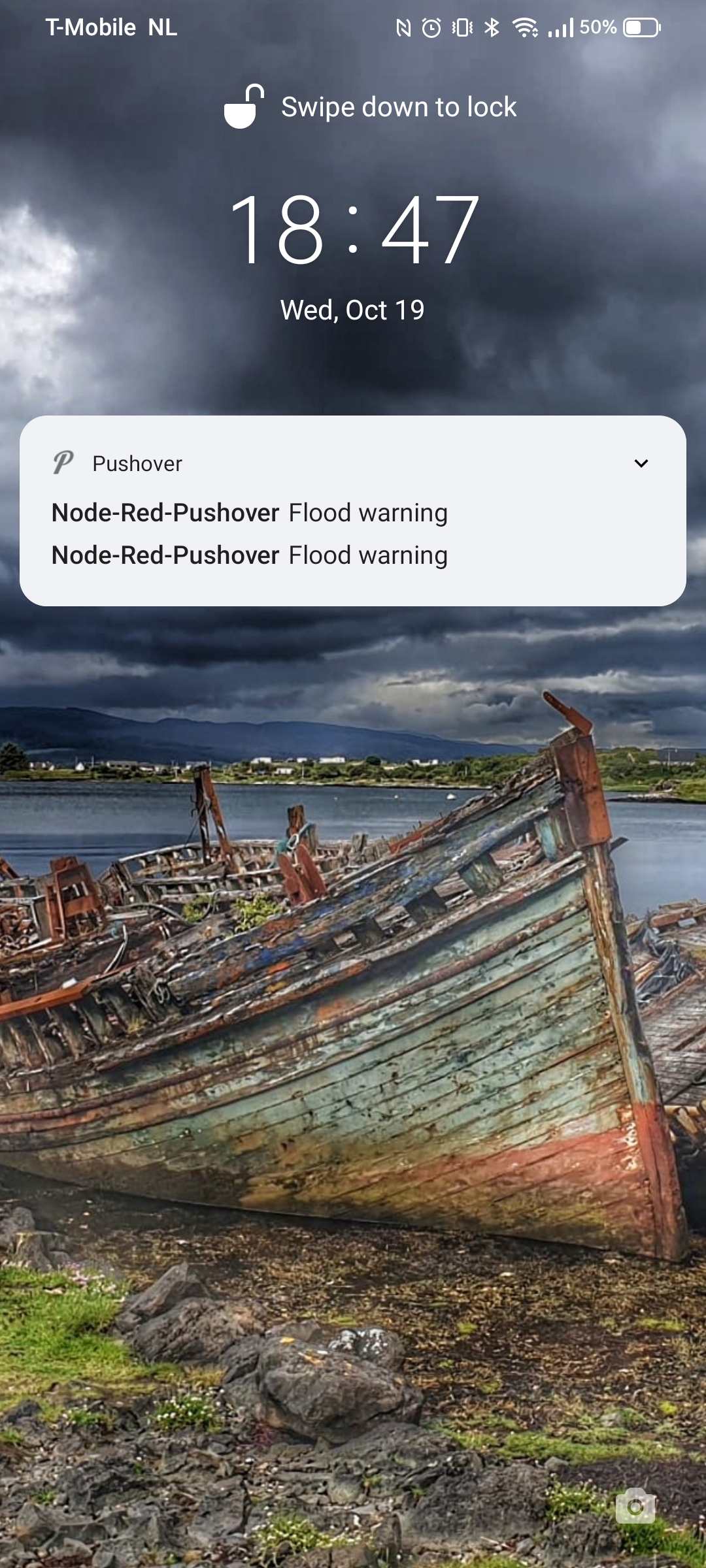
Sends a MQTT message (when not connected to the cloud like i have) MQTT is a alarm message AND it wil send the temperature of the device!
After a while (when dry) goes back to sleep
There are connection point on the print you can use .. happy hacking!
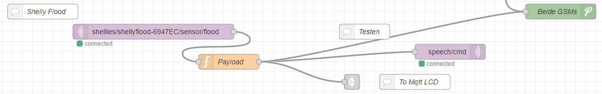
My node-red configuration
Above is the part where the mqtt messages gets processed by Node-Red Sending it to PushOver and my little MqttLcdNotifier
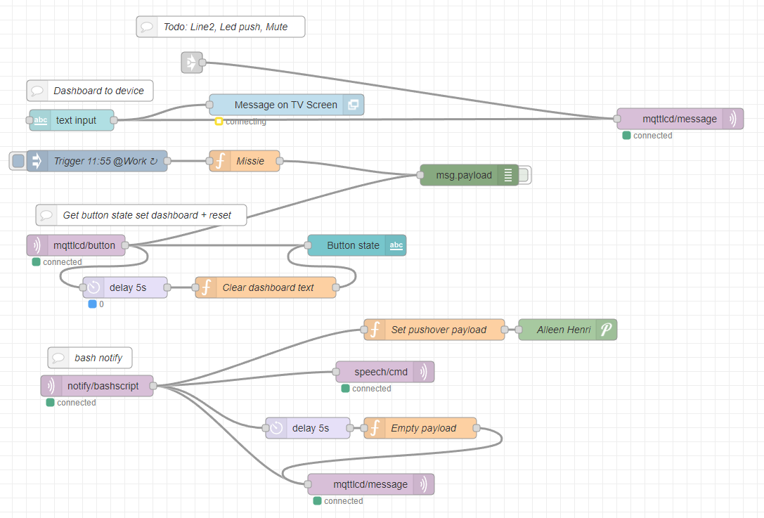
Above is the MqttLcdNotifer .. there are several parts to this
Top line is from shelly flood and other notifications
Text input puts text from the NR GUI on my TV and the LCDDisplay
same parts are being used by my 3D printer when the print tool is getting TO hot, or printing is finished
Trigger at work WAS a notification for work .. nonfunc
mqttlcd-button is the mqtt message send from the display (the one that i was pushing) to stop the beeping and clears the display
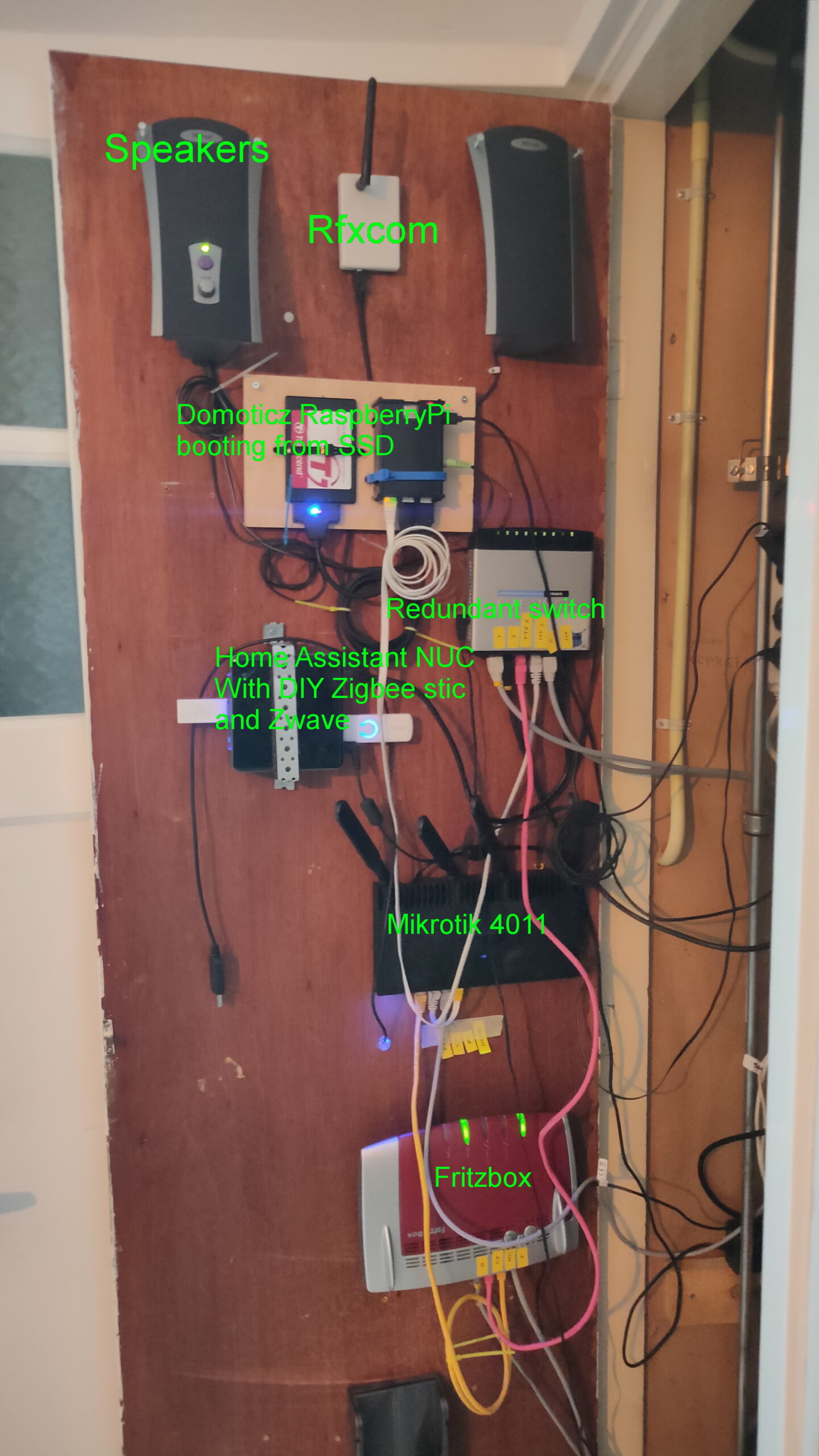
Bash notify, is as previously posted a flow which i can control from my linux machines notify “compiling complete” for example. This is also being broadcast from my livingroom using speakers. (See separate post about this)
Wellll, put this in place 2 years ago, never looked at it again .. still works
Volume is low, due to alarm sounds 🙂
"If something is worth doing, it's worth overdoing."