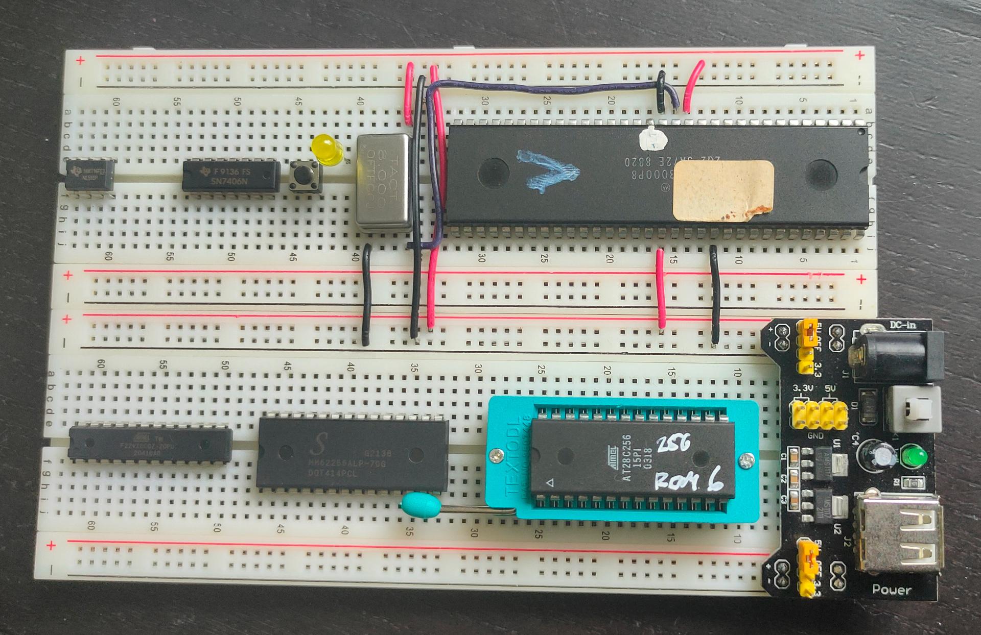
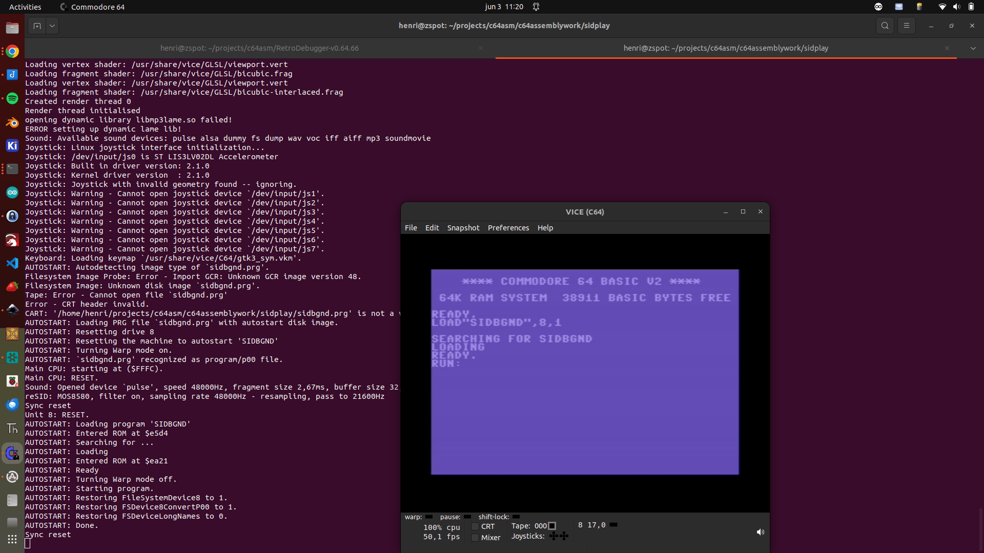
For my new SBC I’ll need a machine code build environment.
This is what I’ve setup now.
My main workstation is Linux based. While this setup is Linux based, vasm should work on other operating systems also.
Getting and compiling vasm for 68k
wget http://sun.hasenbraten.de/vasm/release/vasm.tar.gz
tar xzvf vasm.tar.gz
cd vasm
# Building
make CPU=m68k SYNTAX=oldstyle
# Using
./vasmm68k_oldstyle -m68000 -Fbin -dotdir -no-opt source.asm
# this generates a.out
# Dumping the file (byte separated and with a offset of 0x8000)
xxd -g 1 -o 0x8000 a.out | head
00008000: 30 3c aa aa 4e f9 00 00 80 04 00 00 00 00 00 00 0<..N...........
00008010: 00 00 00 00 00 00 00 00 00 00 00 00 00 00 00 00 ................
00008020: 00 00 00 00 00 00 00 00 00 00 00 00 00 00 00 00 ................
00008030: 00 00 00 00 00 00 00 00 00 00 00 00 00 00 00 00 ................
00008040: 00 00 00 00 00 00 00 00 00 00 00 00 00 00 00 00 ................
00008050: 00 00 00 00 00 00 00 00 00 00 00 00 00 00 00 00 ................
00008060: 00 00 00 00 00 00 00 00 00 00 00 00 00 00 00 00 ................
00008070: 00 00 00 00 00 00 00 00 00 00 00 00 00 00 00 00 ................
00008080: 00 00 00 00 00 00 00 00 00 00 00 00 00 00 00 00 ................
00008090: 00 00 00 00 00 00 00 00 00 00 00 00 00 00 00 00 ................
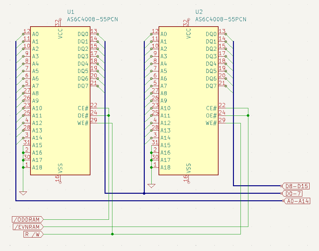
# But my 68k needs an ODD EVEN eeprom
# so I used another tool - romsplit
git clone https://github.com/ullman/romsplit
cd romsplit
make all
# Using romsplit
./romsplit -s a.out odd.rom even.rom
# Split into 4? Split the splits using above
# Output
xxd -g 1 -o 0x8000 odd | head -1 ; xxd -g 1 -o 0x8000 even | head -1
00008000: 30 aa 4e 00 80 00 00 00 00 00 00 00 00 00 00 00 0.N.............
00008000: 3c aa f9 00 04 00 00 00 00 00 00 00 00 00 00 00 <...............
# Burn these with minipro
Disassemble
m68k-linux-gnu-objdump --disassemble-all --target=binary --architecture=m68k a.out
68030 example for friend
# Compile vasm with
make CPU=m68k SYNTAX=mot
------------
vasmm68k_mot  -Fbin  ./edk.asm
-------------
.68030

	ORG $0

*****
* exception table (256 x 4 bytes)
*****
	dc.l $400	; Program Counter na reset (startadres)
	dc.l $20000	; stackpointer (ram locatie)
	dc.l 0,0,0,0,0,0,0,0,0,0,0,0,0,0

	dc.l 0,0,0,0,0,0,0,0,0,0,0,0,0,0,0,0
	dc.l 0,0,0,0,0,0,0,0,0,0,0,0,0,0,0,0
	dc.l 0,0,0,0,0,0,0,0,0,0,0,0,0,0,0,0
	dc.l 0,0,0,0,0,0,0,0,0,0,0,0,0,0,0,0
	dc.l 0,0,0,0,0,0,0,0,0,0,0,0,0,0,0,0
	dc.l 0,0,0,0,0,0,0,0,0,0,0,0,0,0,0,0
	dc.l 0,0,0,0,0,0,0,0,0,0,0,0,0,0,0,0
	dc.l 0,0,0,0,0,0,0,0,0,0,0,0,0,0,0,0
	dc.l 0,0,0,0,0,0,0,0,0,0,0,0,0,0,0,0
	dc.l 0,0,0,0,0,0,0,0,0,0,0,0,0,0,0,0
	dc.l 0,0,0,0,0,0,0,0,0,0,0,0,0,0,0,0
	dc.l 0,0,0,0,0,0,0,0,0,0,0,0,0,0,0,0
	dc.l 0,0,0,0,0,0,0,0,0,0,0,0,0,0,0,0
	dc.l 0,0,0,0,0,0,0,0,0,0,0,0,0,0,0,0
	dc.l 0,0,0,0,0,0,0,0,0,0,0,0,0,0,0,0

	org $400	; hier starten
	move.l #$0,d0
loop1:
	add.l #$1,d0
	cmp.l #$10000,d0
	bne loop1

	move.l #$0,d0
loop2:
	add.l #$1,d0
	cmp.l #$10000,d0
	bne loop2

	nop
	nop
	nop
-----
vasm 1.9f (c) in 2002-2023 Volker Barthelmann
vasm M68k/CPU32/ColdFire cpu backend 2.6c (c) 2002-2023 Frank Wille
vasm motorola syntax module 3.18 (c) 2002-2023 Frank Wille
vasm binary output module 2.3a (c) 2002-2023 Volker Barthelmann and Frank Wille

org0001:0(acrwx1):	           0 bytes
org0002:0(acrwx1):	        1024 bytes
org0003:400(acrwx2):	          30 bytes
-----
-rw-rw-r--  1 henri    henri       1054 aug 27 11:45  a.out