Tag Archives: retro

Old mystery motherboard and Bios hacking

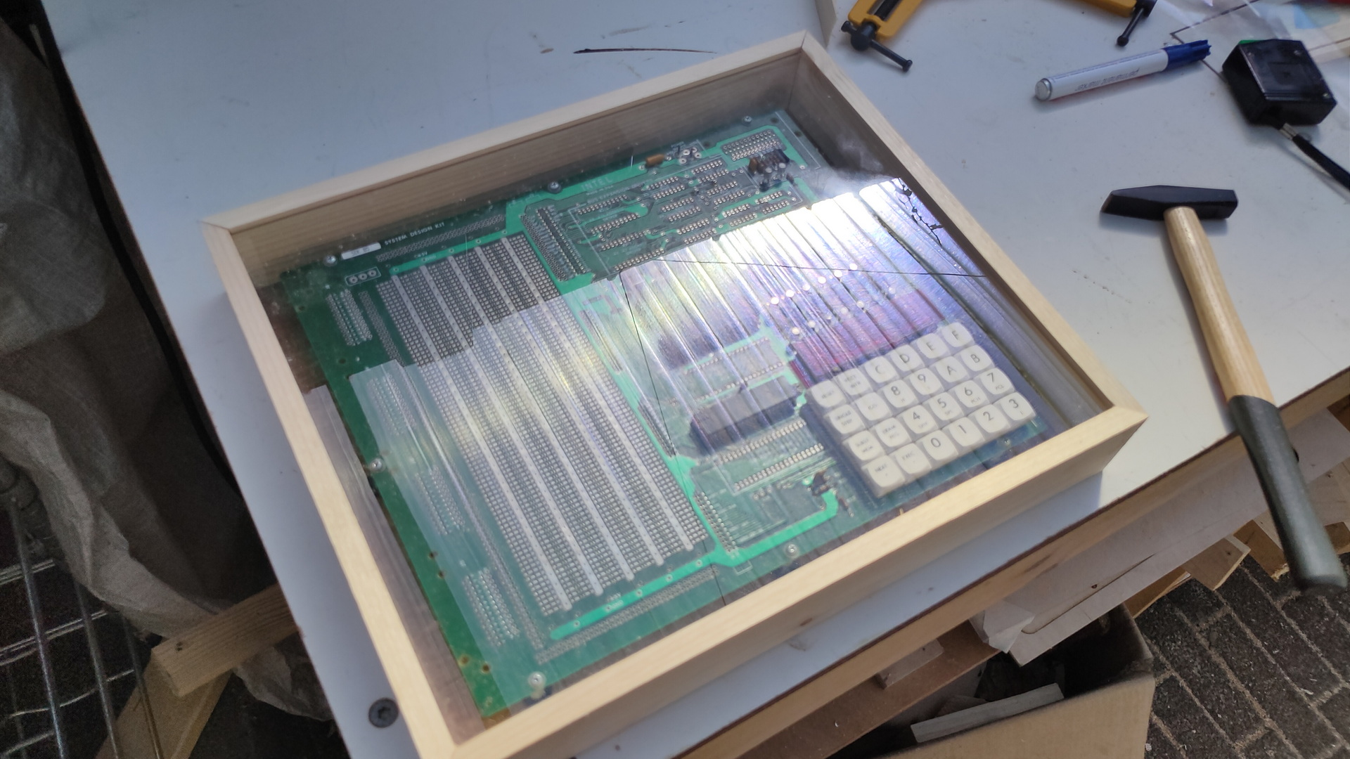
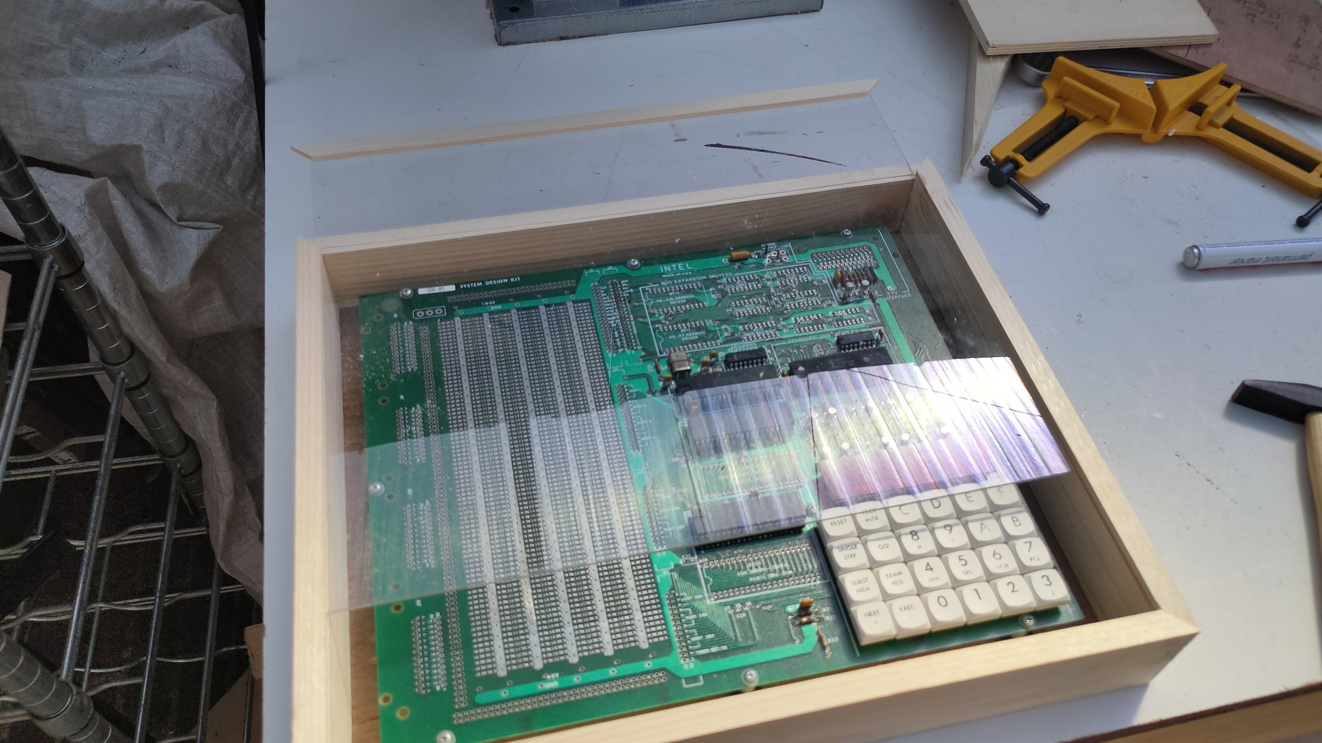
When selling a large part of my computer collection I kept a few odd pieces.

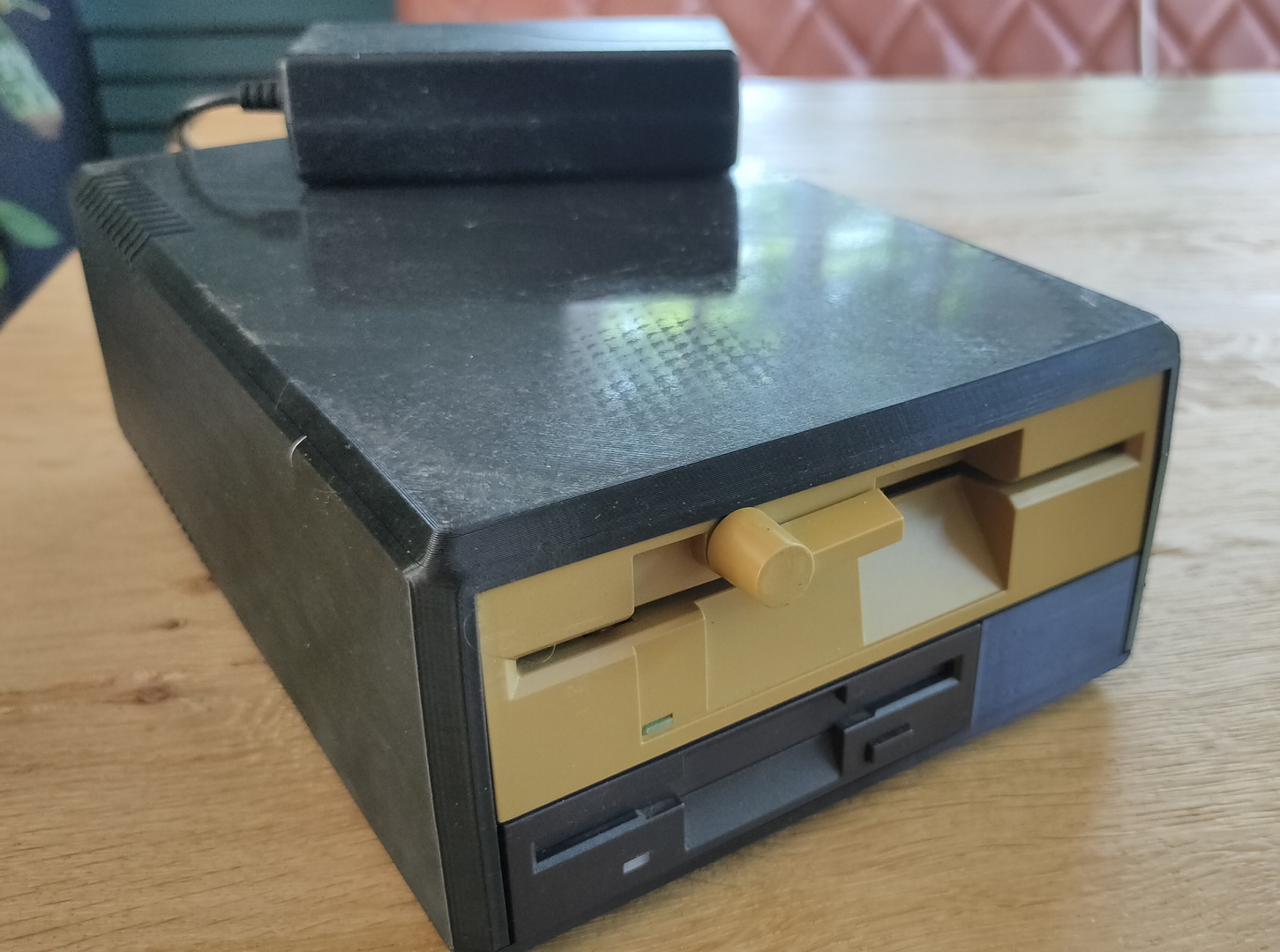
Amongst those was a 8088 DIY machine.

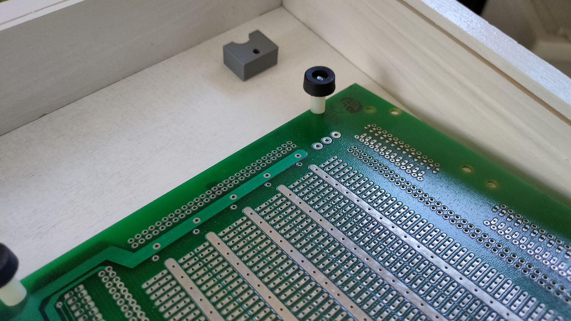
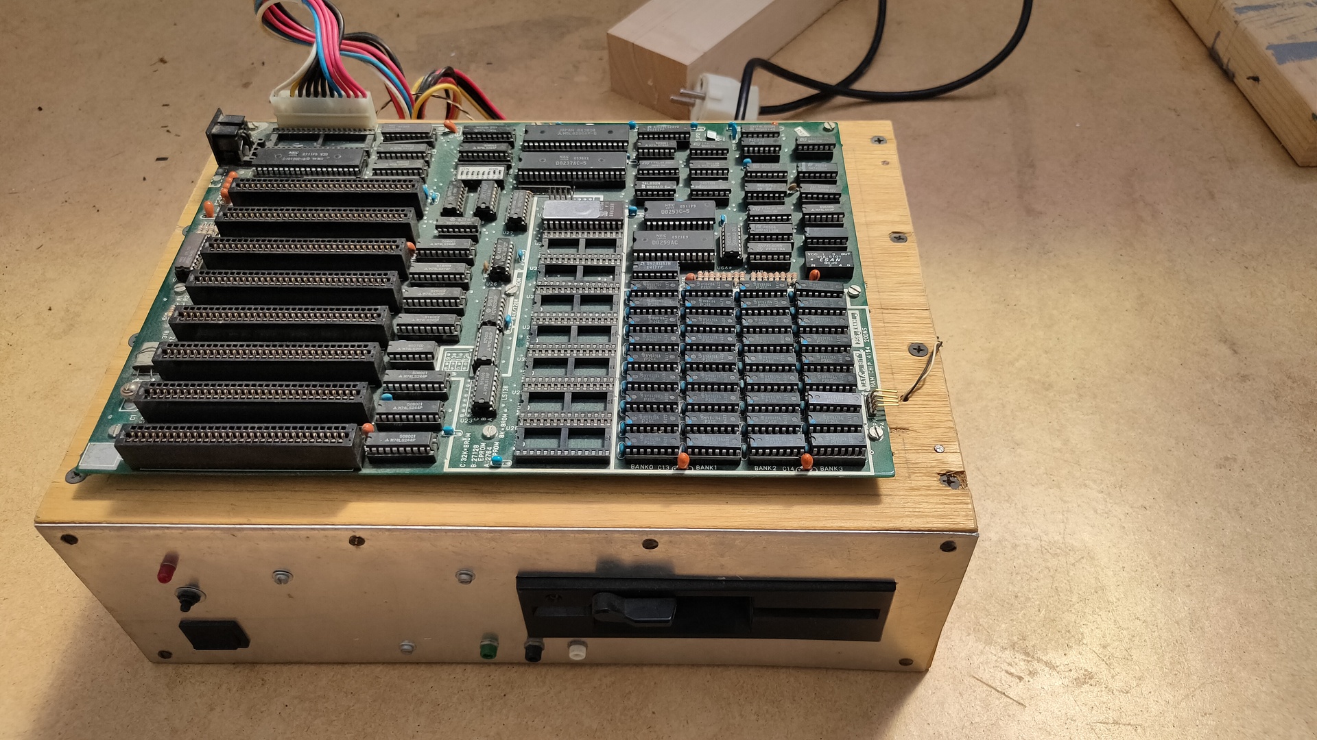
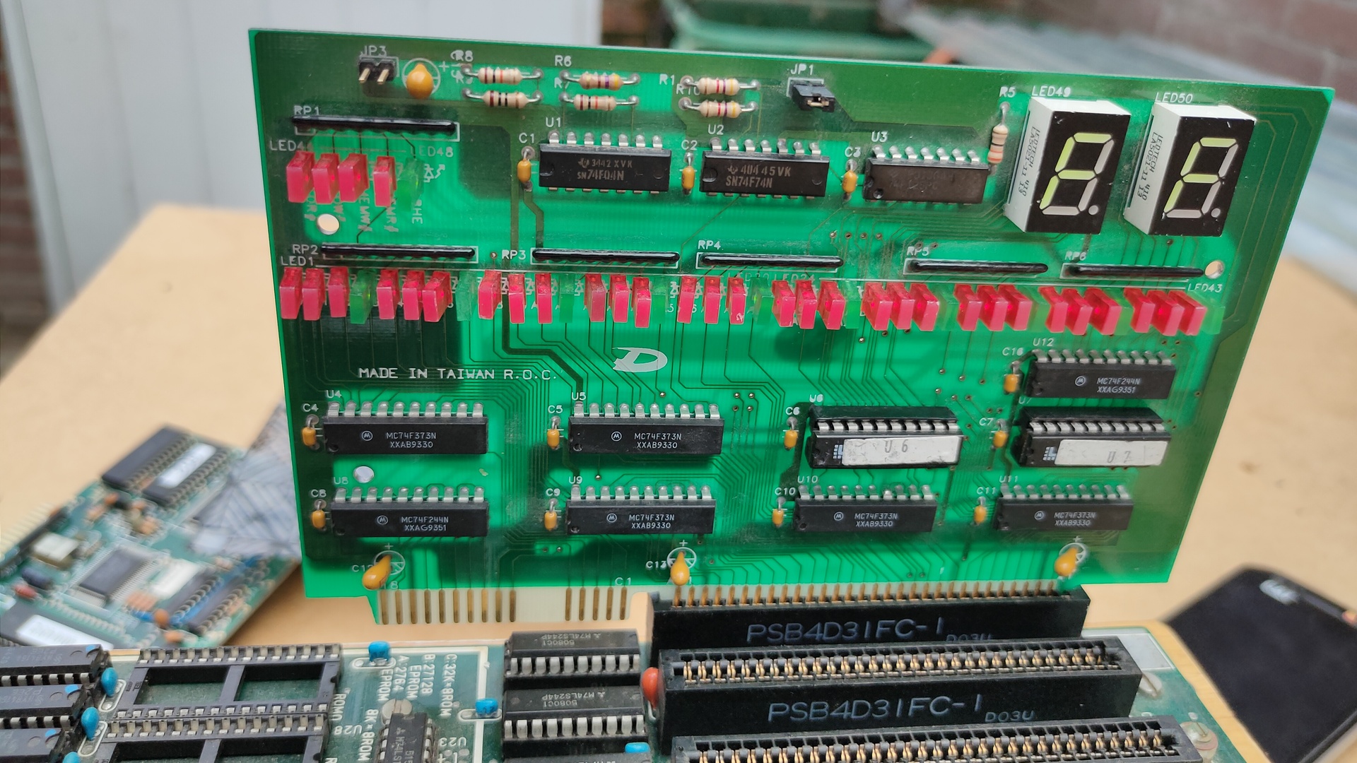
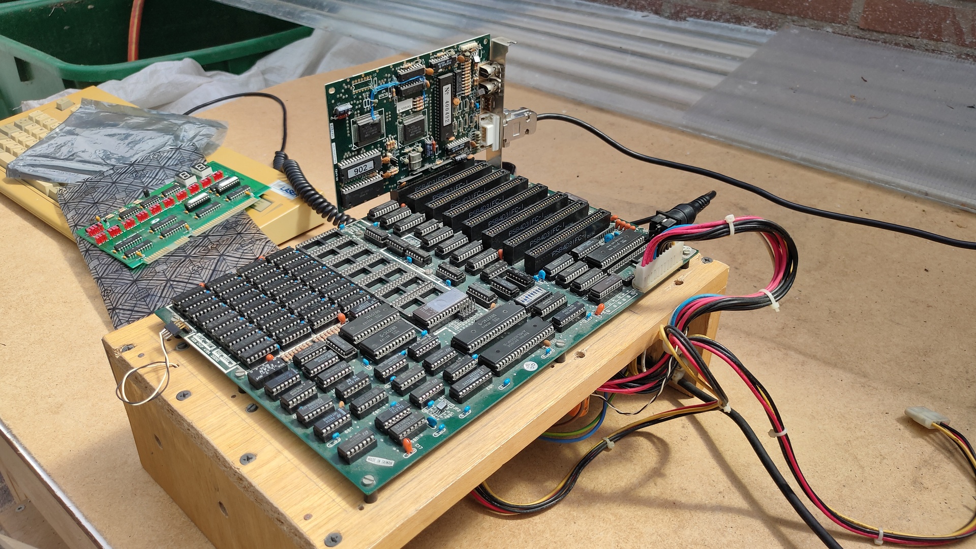
It is a 50PTX3 motherboard with a 8088 compatible CPU

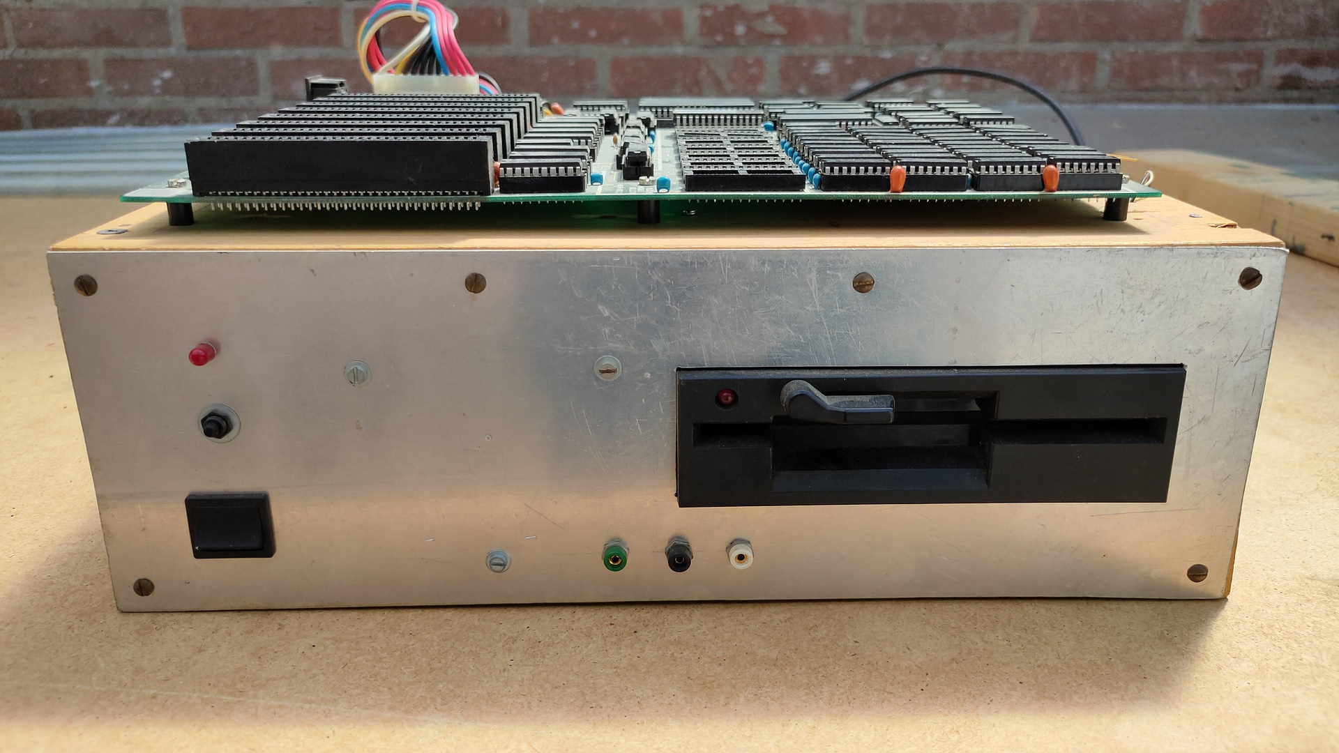
  • Power light (Not LED) and connected to power adaptor, not motherboard
  • Reset button??? not connected
  • Power switch
  • Mid center, 5v gnd and 12v
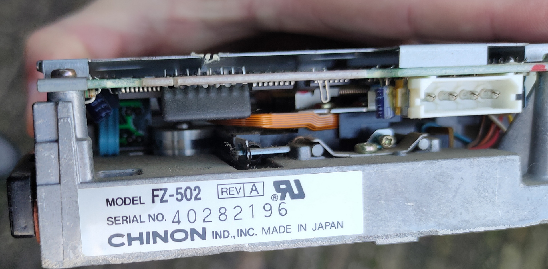
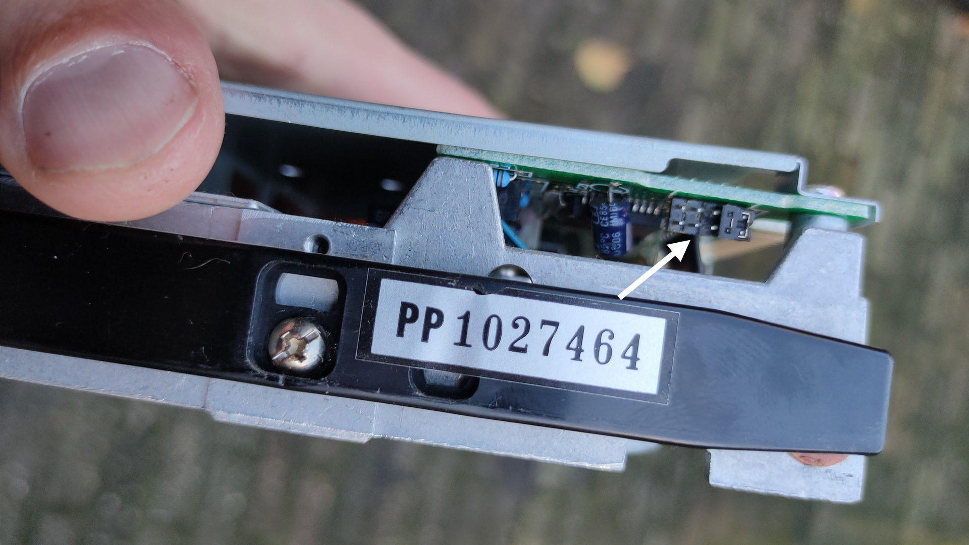
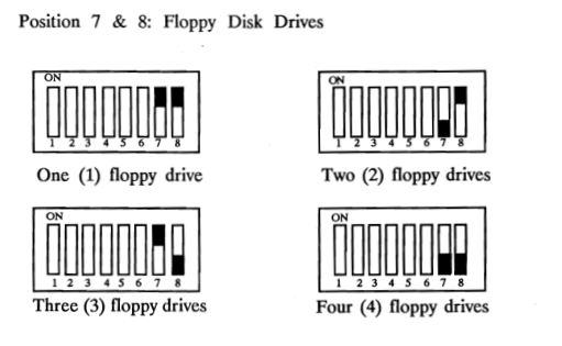
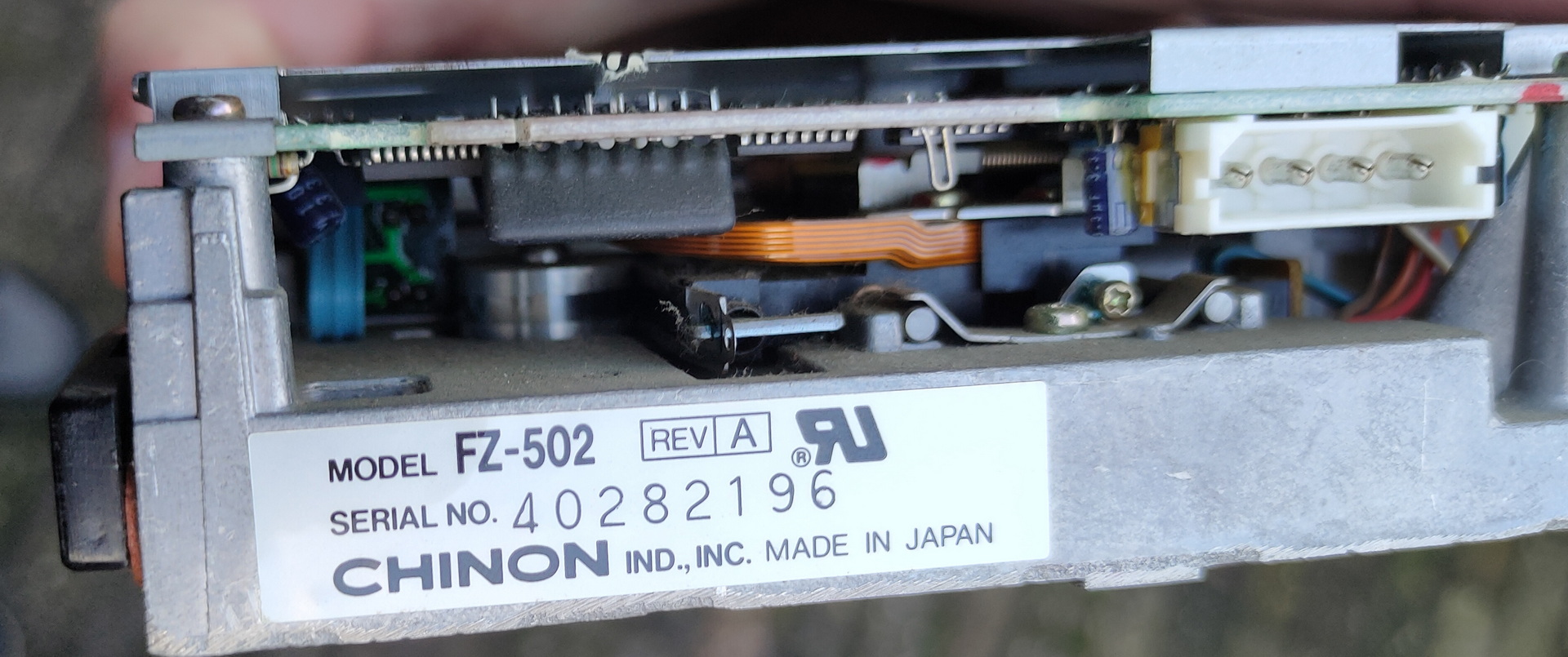
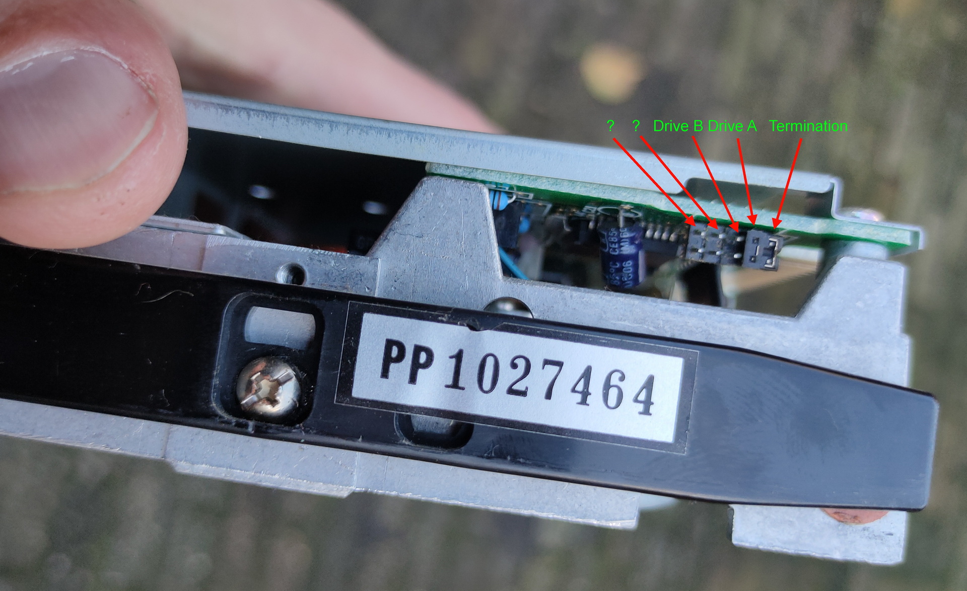
  • 5.25″ drive not connected
Bottom

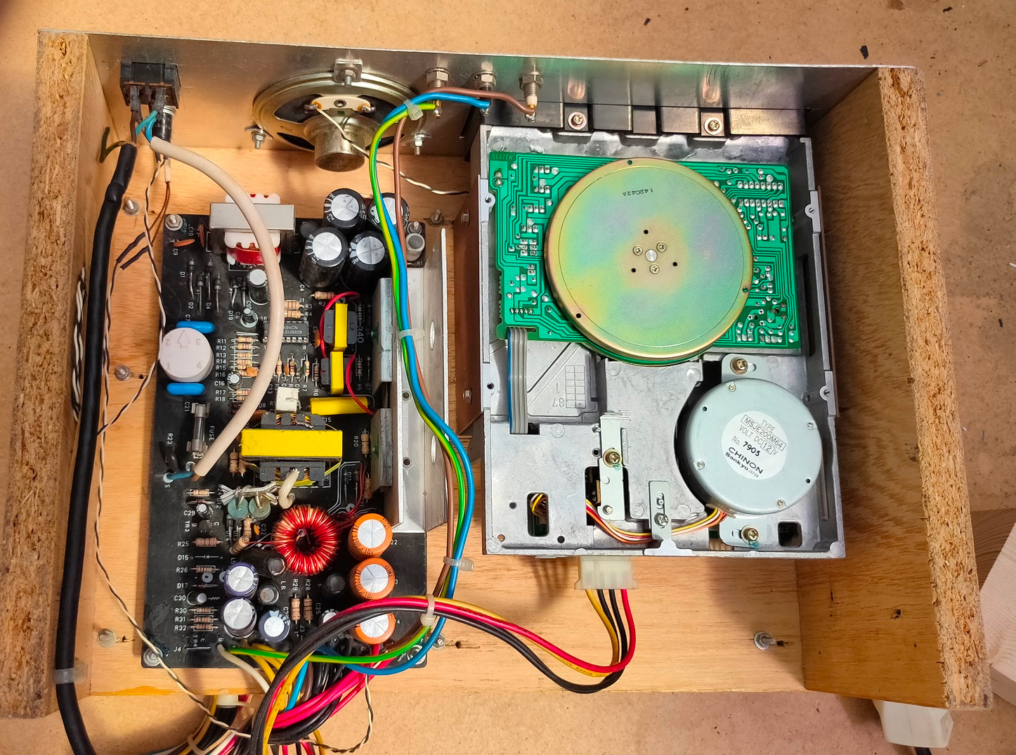
Tested the power adapter first, a nice 5V and 12V.
Then I plugged the power in the Motherboard add plugged a test ISA card in the slot.
After turning the machine on I saw the Address leds flashing

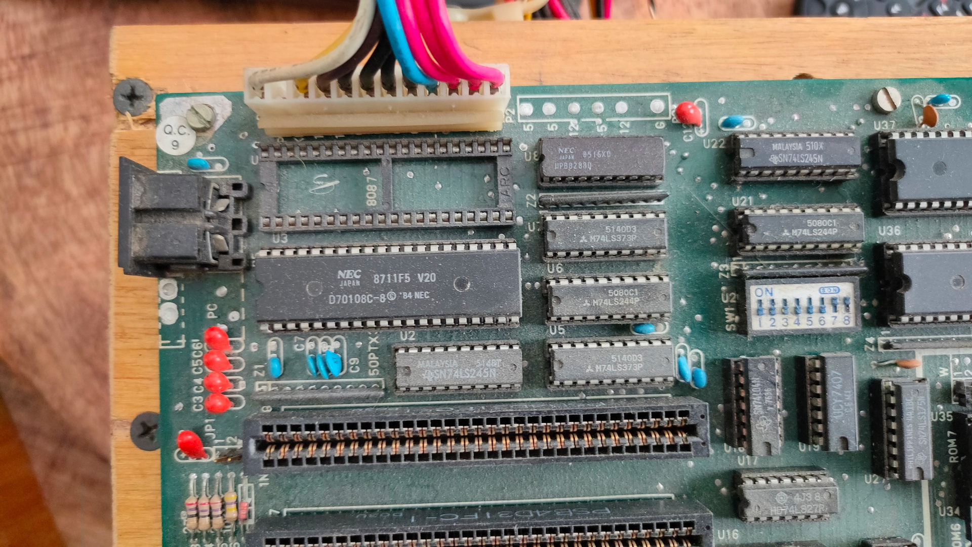
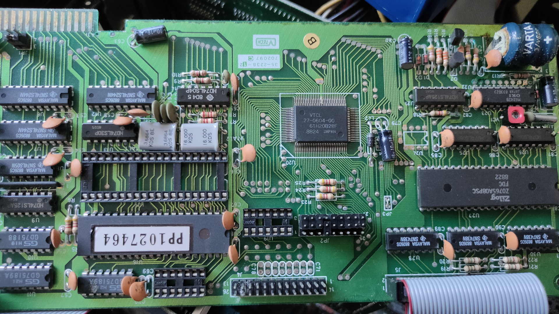
A NEC D70108C from 1984, which is 8088 pin compatible with Intel 8088 but faster, and has some extra functionality.
The empty socket is for the 8087 Co-processor.

Nec V20 versus 8088

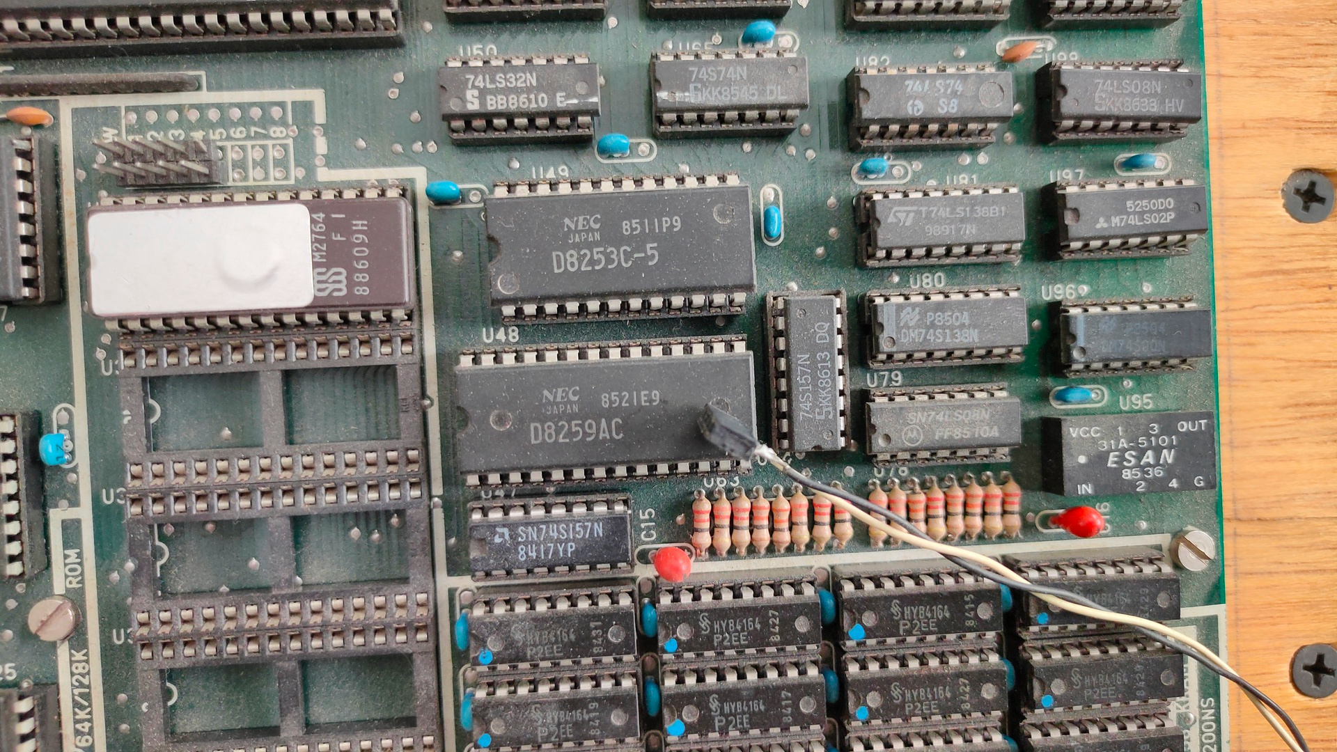
Everything pretty dirty

Rom 2764 (8Kb) and a disconnected speaker wire.

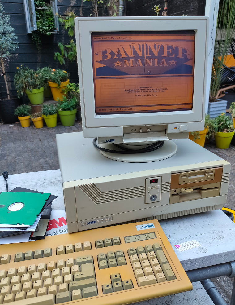
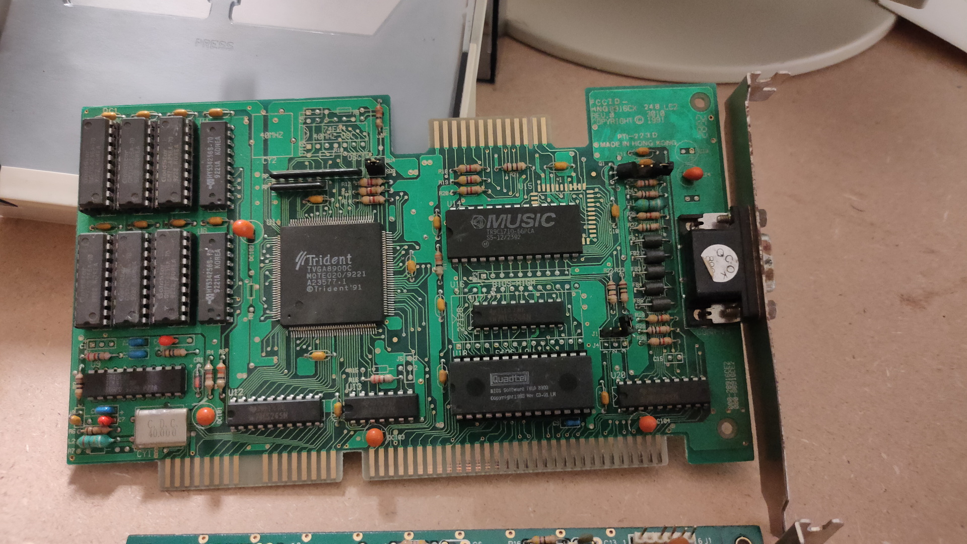
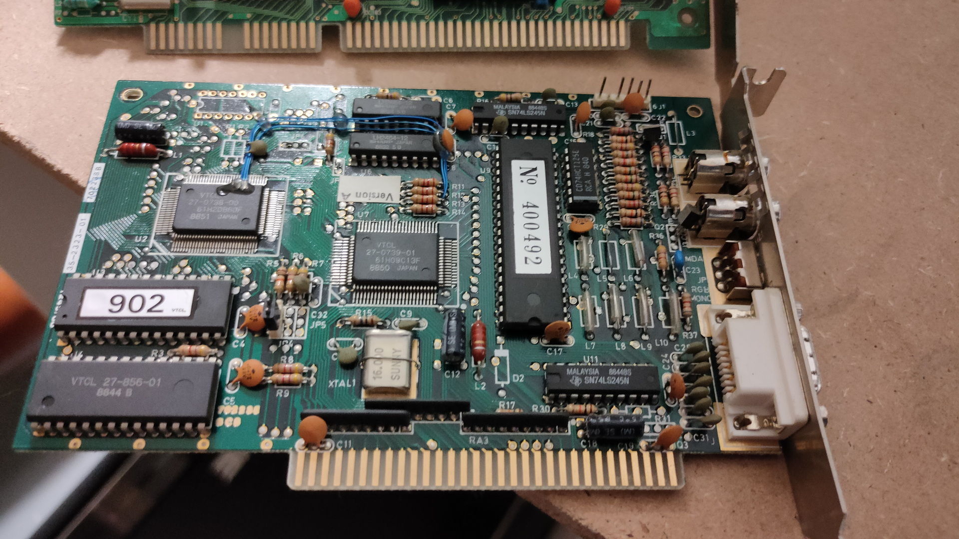
Adding an 8bit Isa hercules/CGA card.

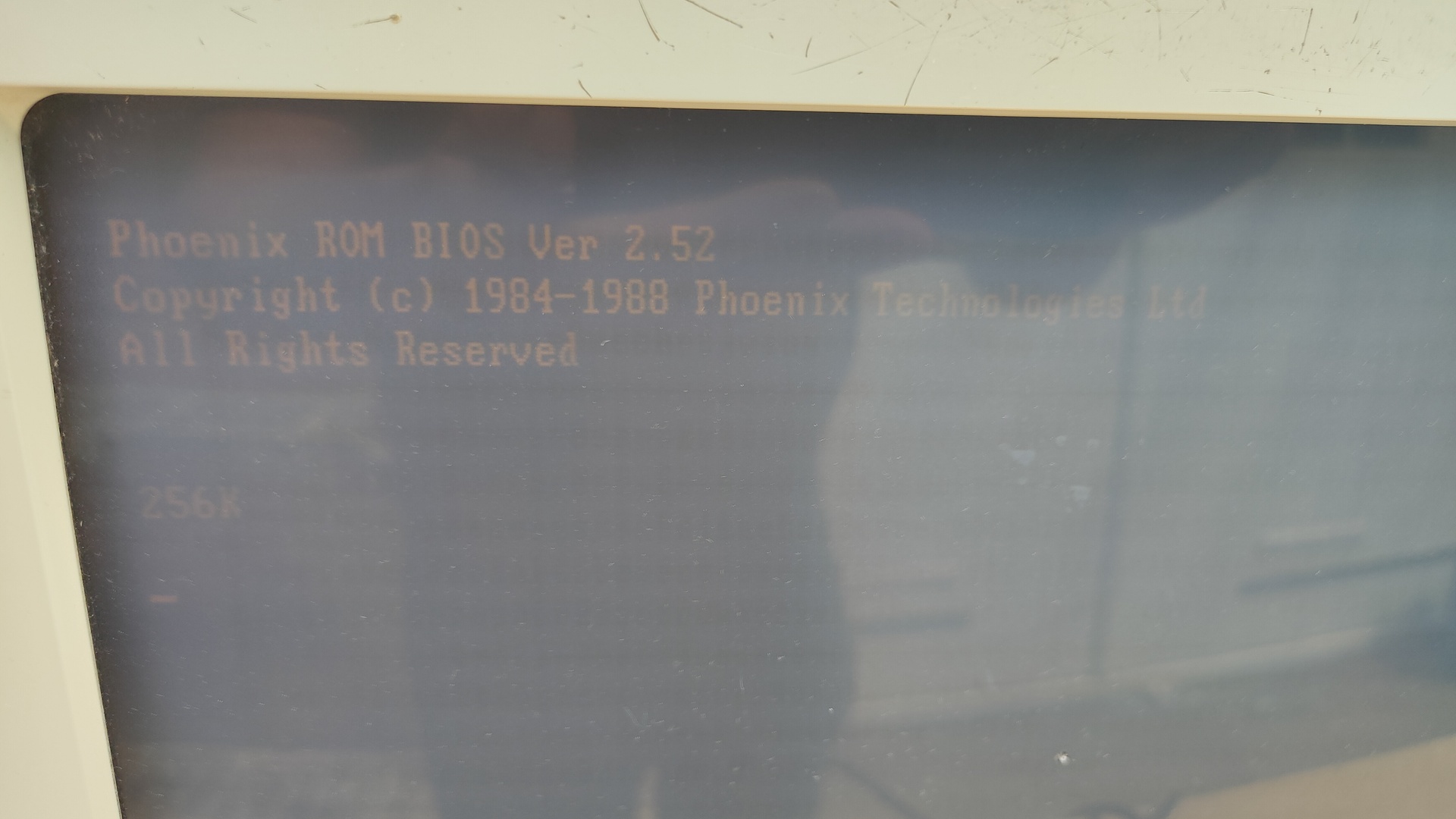
It starts! .. But there is no Floppy controller (yet)

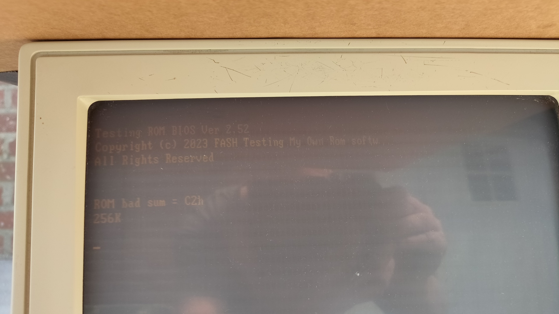
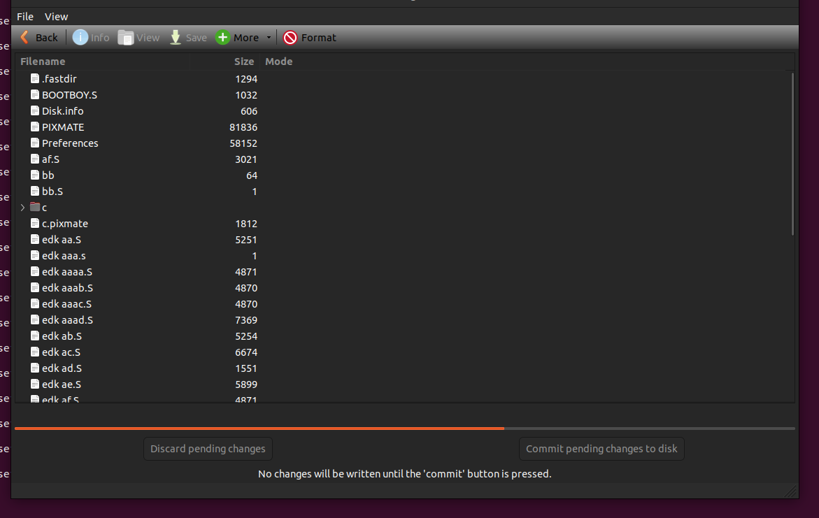
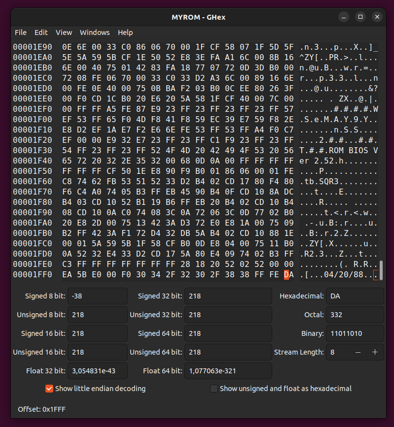
I’ve dumped the Bios to a file and used a hexeditor to play around.
So that’s why there is a bad checksum.

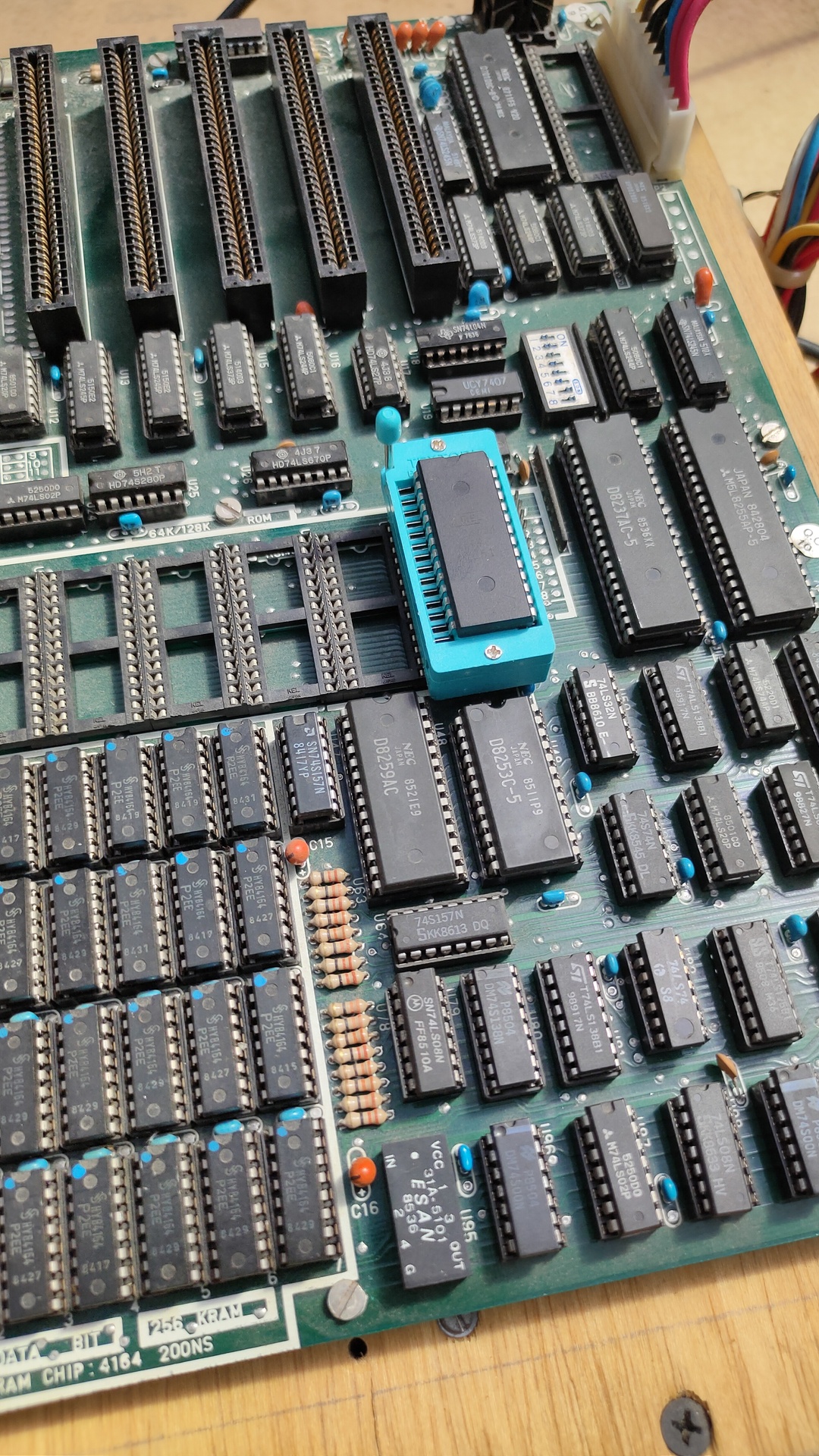
Installing a ZIF socket (Zero Insertion Force) to make things easier to modify.

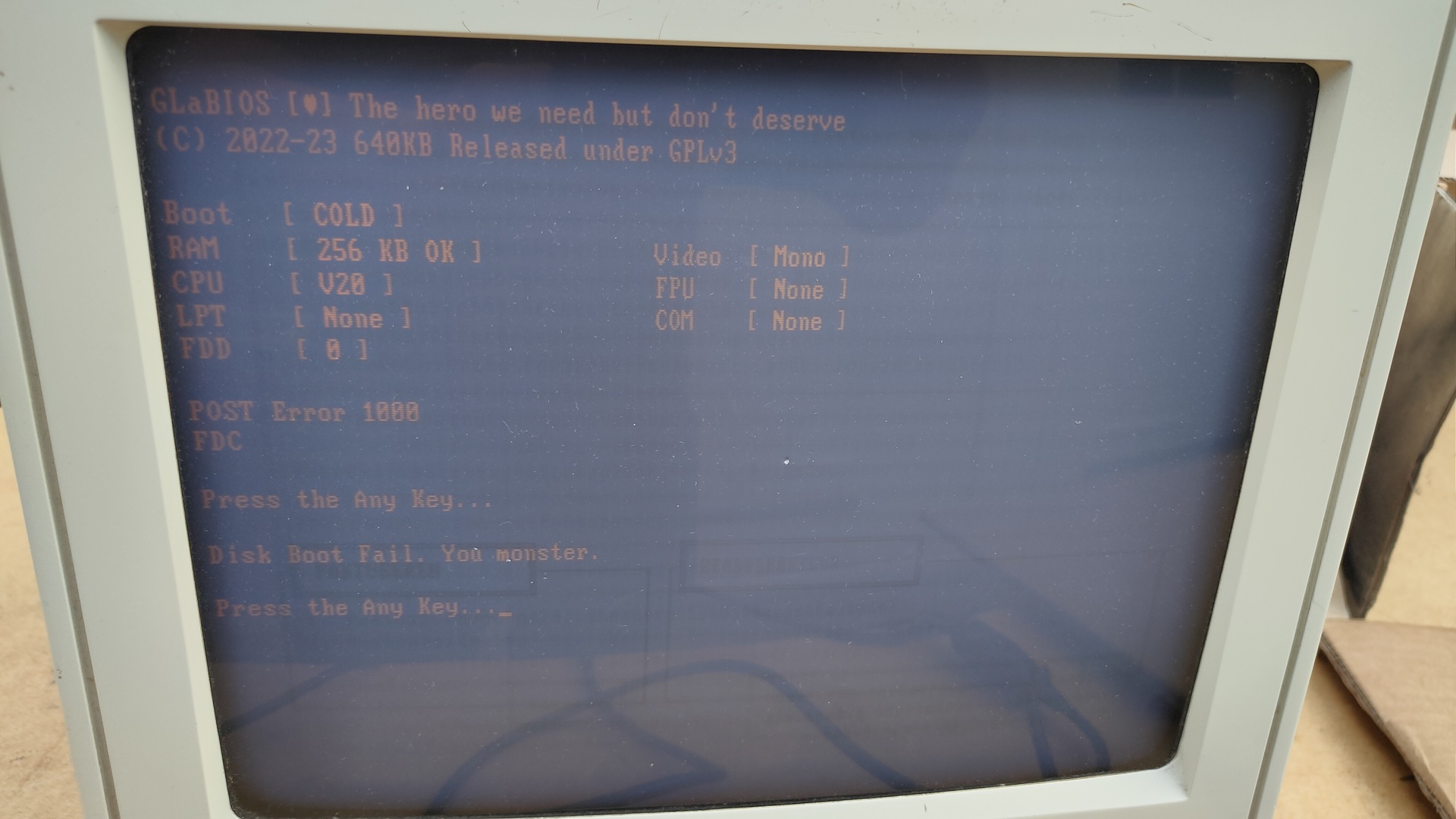
Burned GlaBios on the Eprom and now I can continue to play around.

So why? Why this all ..

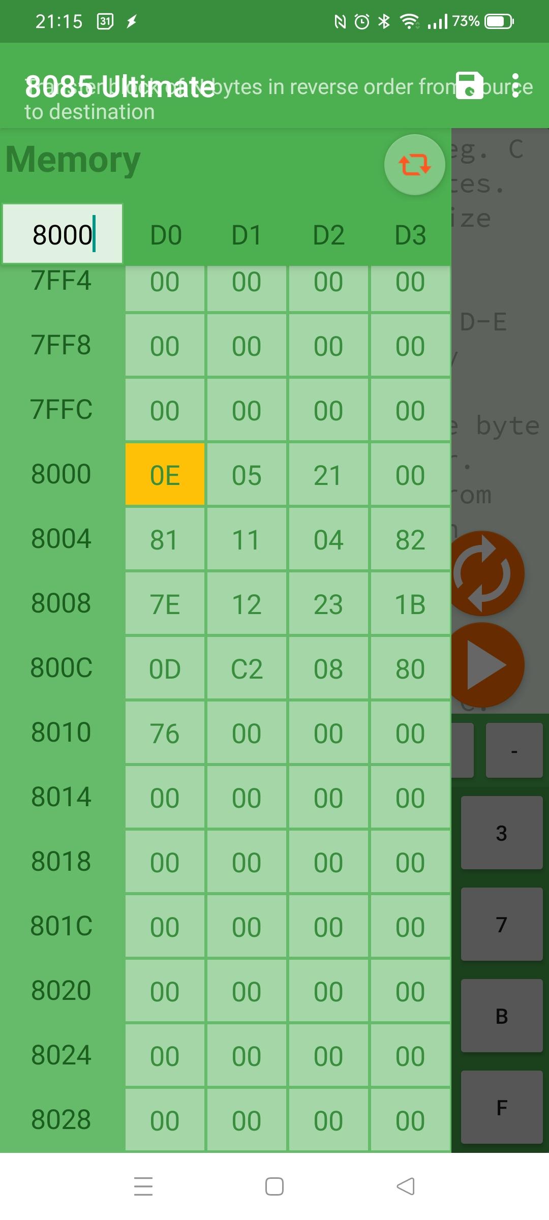
I want to play around with old 8088 assembly code again, but not as I did before using a Dos machine, but hardcoded into Eproms.
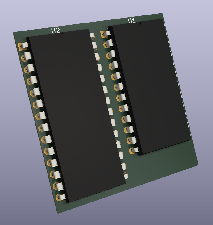
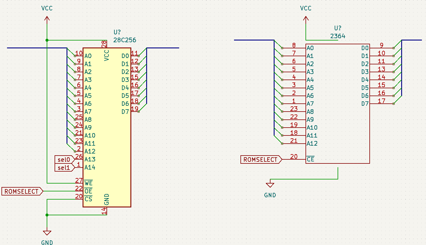
I’ve got 8 banks for ROMs and the source code for GlaBios is available.

In the past Edk and me wrote a boot demo, so it was not utilizing Ms-Dos functions. Maybe i can get some graphical and sound stuff working straight from the Bios.

Some commands:

# Dump the bios to file
minipro -w original.rom -p AT2764A@DIP28

xxd and hexdump to view the dump

I've used ghex to alter the ROM

# Write a new bios to a 28C64 (same Eeprom i've used for the C64 Cartridges)
minipro -w /home/henri/Downloads/MYROM -p AT28C64
 

GlaBios source code:
https://github.com/640-KB/GLaBIOS/blob/main/src/GLABIOS.ASM

I was planning to disassemble the Phoenix Bios, but it’s quite hard to differentiate between code and data, there are no named pointers and you have to interpret every line of code.

So GlaBios it is ..

First code to look at:

This is after the whole post reset.
There is a reset pointer at ffff:fffe
Which points to the bootstrap routine, which ends in below machine code.
I'm going to plug my own code over here.

(See the funny remark about Monster as being displayed in one of above pictures)

;----------------------------------------------------------------------------;
; INT 18 - Unbootable IPL
;----------------------------------------------------------------------------;
; Display a disk boot failure message and wait for a key to cold reboot.
;
; This may be re-vectored to ROM BASIC, if present.
;
; Size: 18 bytes
;----------------------------------------------------------------------------;
INT_18 PROC
		ASSUME DS:_BDA_ABS
	PRINT_SZ  BOOT_FAIL			; print boot failure string
	XOR	AX, AX				; AH = 0 (wait for key)
	MOV	DS, AX				; DS = 0000
	MOV	WARM_FLAG_ABS, AX			; do a cold boot
	INT	16H					; wait for key press
	JMP	BOOT					; reboot
INT_18 ENDP

BOOT ENDP

;----------------------------------------------------------------------------;
;
; END OF BIOS POST/BOOTSTRAP
;
;----------------------------------------------------------------------------;

		ASSUME DS:_BDA
STRINGS PROC
;----------------------------------------------------------------------------;
; Banner Strings
;
BANNER_STRINGS PROC

					IF POST_GLADOS EQ 1
BOOT_BEGIN		DB	CR, LF
			DB	'Starting GLaDOS...'
NL2_Z			DB	LF				; two NL's, null term'd
					ENDIF
NL_Z			DB	CR, LF, 0			; one NL, null term'd
BOOT_FAIL		DB	'Disk Boot Fail.'
			DB	' You monster.'
NL2_ANY_KEY		DB	LF
NL_ANY_KEY		DB	CR, LF
ANY_KEY		DB	'Press the Any Key'
			DB	'...'

Assembly stuff

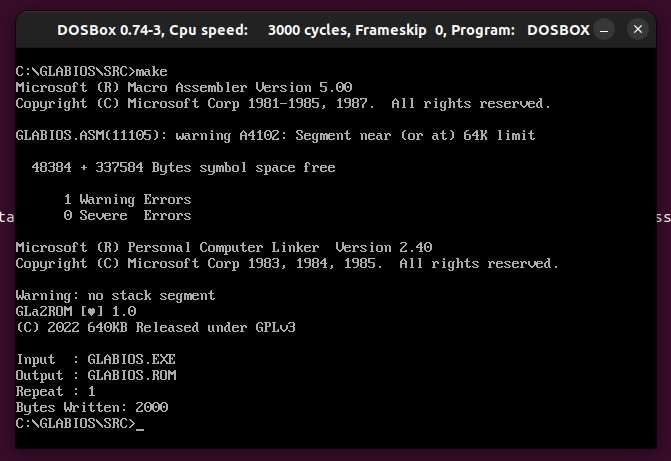
I’ve got Dosbox installed on my machine.

git clone https://github.com/640-KB/GLaBIOS.git
I copied MASM.EXE and LINK.EXE in the GLaBios src directory.

edit make.bat

change
MASM GLABIOS;
into
MASM /DVER_DATE=”05/24/23″ /DARCH_TYPE=”T” /DCPU_TYPE=”V” GLABIOS;
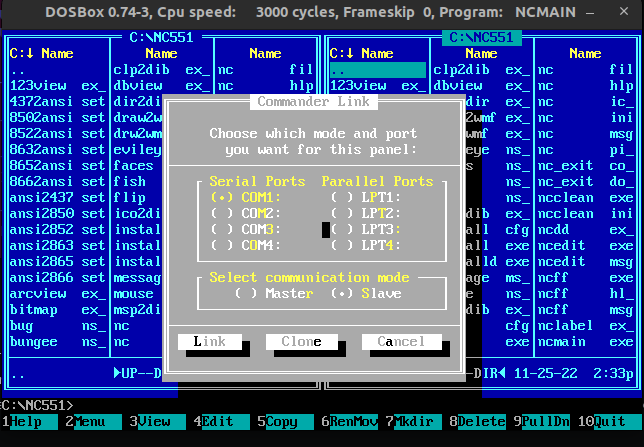
start dosbox

mount c: /home/henri/projects/

c:

cd glabios/src

make.bat

SDK-85 Cassettes

Started drawing a Cassette interface in Kicad.
This so i can read back my old cassettes with programs.
(And write some new stuff)

I’m planning to buy a small micro cassette player.
With schematic below, I’m going to use it as save/load device.
But also with the same player, I’m going to convert the tape to a wave file, and try to decode the program using python.

While I’m at it, reading the old manuals, a RS-232 interface would be nice also!

UPDATE 20231016

This is the final version

Information about the 7655A.
A eprom WITH IO ports! Amazing piece of history hardware.

Testing some sims on Linux and Android

JiffyDos notes (work in progress)

JiffyDOS is an enhanced DOS for the C64. The software is programmed onto ROM chips that replace the Kernal ROM chip on the motherboard and the DOS ROM chip in the disk drive. JiffyDOS is intended to provide greater speed, commands and convenience than on stock systems.

The 1541 drive is a computer on its own, using a 6502 and VIA chips.
(See other pages) (C64 uses a 6510, that is the same slightly modified version of the 6502)
A cool example of the drive being an OS/computer on its own:
https://www.youtube.com/watch?v=zprSxCMlECA

Some notes:

  • I want to use a larger rom and using the higher address lines as kernal selector. Address line A13 and A14 can be used as selector
  • There is a schematic out there using runstop at boottime to do de selection of the rom part

Did I misspell kernel? NO
(Below from Wikipedia)

The KERNAL was known as kernel inside of Commodore since the PET days, but in 1980 Robert Russell misspelled the word as kernal in his notebooks. When Commodore technical writers Neil Harris and Andy Finkel collected Russell’s notes and used them as the basis for the VIC-20 programmer’s manual, the misspelling followed them along and stuck.

Original Kernal: 901227-03
8-kilobyte 2364 ROM 4K * 8 bits PROM

28C265 = 32K * 8bits

Diffference in ROM size AND there are some other pin placements.
V0.1

Romselect should be /(a15 * a14 * a13) depending on ram/rom switch.


SEL0SEL1
00rom0
01rom1
10rom2
11rom3

$E000-$FFFF – ROM
57344-65535

KERNAL ROM or RAM area (8192 bytes); depends on the value of bits #0-#2 of the processor port at memory address $0001
$FFFA-$FFFF – hardware vectors

%x0x: RAM area.

%x1x: KERNAL ROM.

3D printing problem and Fluxengine

3D printed a case for my fluxengine.

Last week I got my 1.2MB 5.25″ drive.
And tested it with the fluxengine.
Now i can read old 5.25″ disks again. And convert these to disk images.
Amiga/Atari ST/C64 (single side) and my old MSDos disks.
(That’s what I’m using, the fluxengine can read many more)

Why single side C64? you ask?
Those are flippy disks, that means they are single sided and you flip the disk in the drive to read the other side.

Why can’t the fluxengine read those?

  • There is only one sensor in my drive.
  • Reading side 2 without turning the disk won’t work, the sectors are in reverse!
    (Maybe there is a trick to read in reverse? Fluxengine is reading and decoding raw disk sectors, but i have to read into this)

Note: The 1541 Drive for the commodore’s is a complete 6502 computer with 2x 6522 VIA and ram/rom chips! (2016-15 2K x 8 bit Static RAM / 27128 16kb x 8)

see: https://www.henriaanstoot.nl/tag/6502/

And this amazing trick:

https://www.youtube.com/watch?v=zprSxCMlECA

Maybe i’m going to modify my 5.25 drive with another index sensor.

So i downloaded a diskdrive case from thingiverse, which can hold 2 drives. 3.5″and 5.25″.
https://www.thingiverse.com/thing:3089895

I started printing the bottom, no problem there. But because of the large size of bottom and top. (Both about a day of printing) I had to change the filament.
But I didn’t have a good look at what I took!
Below is what you get when printing PLA and switch to PETG!

Temperatures for PLA:
Tool: 200 and bed 50
Temperatures for PETG:
Tool: 240 and bed 70


So 12 hours printing and I had to start again.

I could not remove the knob, else I would have removed the beige front and spray painted this black.

Finished a display case for the SDK-85

So i made a nice display case for this SDK.

I made some designs and came up with this:

I just took a 12mm x 60mm piece of wood, and made a slit for the acrylic plastic using a circular saw, and removed a part for the back-plate using a wood router. I found a piece of acrylic in my shed, cut it to the right size using the circular saw. Slapped some paint on the wood.

I want to be able to use the sdk whenever i want, so i made a sliding window thingy. ( With wooden handle so the frame looks intact when closed. )

Then I 3D printed some holders, which I designed using Openscad.

Openscad code

difference(){
difference(){

    translate([0,8,1])
    cube([20,15,10],center=true);
union(){
    cylinder(h=9, d1=9, d2=9, center=true);
translate([0,0,3])
cylinder(h=9, d1=15, d2=15, center=true);
}
   
}
$fn=100;
 translate([0,12,0])
 cylinder(h=30, d1=3.5, d2=3.5, center=true);
}

I will probably add a powerconnector and lasercut a hole for the keypad at a later stage.

Serial link between MSDos and Linux troubles

In post https://www.henriaanstoot.nl/2022/11/25/disk-troubles-or-missing-old-skool-hardware/ i mentioned the serial connectors i’ve bought to connect the Laser XT to my Workstation to transfer files.

The null modem i’ve made is like mentioned on https://en.wikipedia.org/wiki/Null_modem

I’ve used the loopback handshaking using 3 wires. ( Only using a DB25 and a DB9 on the other end )

So i configured the Linux side as follows.

I’ve tried two usb to serial converters.

Both when trying on windows 10 are not supported any more

Dec 14 17:34:40 zspot kernel: [ 1082.299607] usb 1-4: pl2303 converter now attached to ttyUSB0

sudo stty -F /dev/ttyUSB0 9600

Then i start dosbox.
To enable a com port i have to enter:

serial1=directserial realport:ttyUSB0

Starting Norton Commander and selecting COM1

After a few seconds i got this ..

What else is there to check?
At least i’ve still got the Flux Engine!

Fluxengine disk reader

I’ve build a drawbridge disk reader in the past:
https://www.henriaanstoot.nl/2022/04/26/started-to-build-a-drawbridge/
I found an even more interesting project.

I was looking for a solution to my XT laser problem.
https://www.henriaanstoot.nl/2022/11/25/disk-troubles-or-missing-old-skool-hardware/

And found this! The fluxengine
https://github.com/davidgiven/fluxengine

An open source project using a small controller board.
“Flashing” some software on the board and soldering a pinheader was easy.
When connecting a flat cable and a floppy drive, you end up with a device which can read many formats. Including dos 1.44/720 and amiga.

Nice package it came in

Using the power from a sata/ide harddisk adaptor

Reading and writing a MSDOS disk, no problem.
Imaging an amiga disk .. easy!

You need to compile some software, but it was well documented

Disk troubles or missing old skool hardware?

I bought a XT Laser/3 a while ago.
And i wanted to get my old programs running on it again.

One of the disk i found was a 5.25 inch boot disk which should contain a boot demo i’ve made in the past with Edk.
But it is the secondary drive in this system. Those old machines lack a bios you can change.
And change A: for B: for example.
Some machines had a program which could alter boot settings. (not this one)
So i was playing with jumpers and dipswitches on the motherboard.
( Drive select / Termination / drive before or after the twist in the flatcable. )

Dipswitches on the motherboard

Wellll leave the boot order for now, i needed to get software on the machine using floppy’s.
I could not find empty HD disks (1.44MB which i wanted to use)
So i took a DD disk and a drill ..

(Image from the internet)

I bought an external usb floppy drive.

Now i have everything to get my programs on the msdos machine.

EXCEPT ….

Diskette didn’t work in the drives.
So i bought new old stock diskettes online.

Now i have everything

WRONG again

Formatted 1.44 disk in USBfloppy drive .. OK
Read in 3.5 drive on the MSDOS machine .. NOT OK
Check drive in MSDOS machine .. is 1.44MB .. OK
… check floppy controller in MSDOS machine .. NOT OKAY
(720kb is 300kbits per second and 1.44 HD 500kbits per second)
So i’m limited to 720kb due to the controller ..


Can the USB Floppy drive read/write 720kb disks .. NO!
( A cheap series made with drives only supporting HD disks )

Alternatives? .. Serial maybe, there is Norton Commander on the MSDOS machine so i could use “link”

Do i still have a USB-RS232 sub-d cable ? YES!
Nullmodem cable? NO
Make a null modem cable .. i’ve made those before .. BUT no sub-d connectors.

I’ve been throwing away too much in the past.

Now i have to buy those things again:

VGA – 8bit ISA – have 2 now
Floppy drive – have one for 1.44
8bit soundblaster compatible – TODO
Nullmodem – well i’ve bought connectors for those

Hercules to VGA

While playing with MuseScore….
(Typesetting some scores for Pipes and Flute)

This came in: WOOOT

Trident 8900C (1024 x768 max 512Kb)

This is a Trident VGA card. While having a 16bit ISA connector, it can work in a 8bits ISA slot.

A while ago i bought a Laser XT/3, that’s the one my parents had.
This is where i did a lot of assembly programming on.
It’s a 8086 cpu, 640K and has a Hercules/CGA graphics card.

I found loads of assembly files and i want to see if i can get it running again.
While some code was written for hercules, ( That’s the monochrome image you see in the example above ) and a few for EGA (4 colors).

Most of it was written for VGA. Probably on a later machine like a 80386?

But i know there are vga cards for 8 bit msdos computers, and i found one. ( This one is even autodetect, so no jumpers to figure out)

So i’ve put this card in the machine, turned it on, and it works!
I’ve got only 2 examples living on the harddisk of the machine, both black and white … 🙂
I have to search for interesting code in hundreds of files.

Some friends of mine, picture was taken from an amiga genlock digitizer
The intro pages of a “amiga emulator” WHERE is the rest??? (end is a cga starfield demo)

Hercules Card

There is not much info available about this card:

  • Max resolution (Hercules) : 720×348
  • 15 pin analog monitor port (CN1)
  • BIOS enabled JP1 Pins 1 & 2 closed
  • BIOS disabled JP1 Pins 2 & 3 closed
  • CGA selected SW1 On
  • MDA (Hercules) selected SW1 Off

Floppy drive boot

My friend EDK and I made some demo’s like

And a boot demo, which was able to start from a bootsector, went into a graphic mode and ran a demo with sound. Edk wrote a sector loader for this.
I have some 5.25 inch floppy disks, labelled boot demo. So i wanted to try this today …
I needed to change the boot order, so i went online to search for jumper settings.

I see a led when it tries to boot, but my disks are probably formatted 720Kb instead of 360Kb, which this drive is.

So …. TODO!

Find a 720Kb floppy drive (5.25 inch), and sort through my code!
There is a 8bit soundblaster compatible soundcard that i bidding on online, hopefully i’ll get it

Assembly and modes

I wasn’t sure how to sort the assembly code into Hercules and VGA compatible, but i used this table (There are also extended modes for higher resolutions)

mode 0x00text 40×25 gray
mode 0x01text 40×25 16 colors
mode 0x02text 80×25
mode 0x03text 80×25 16 color
mode 0x04graphics mode (CGA) 320×200
mode 0x05graphics mode (CGA) 320×200
mode 0x06graphics mode (CGA) 640×200 (B/W)
mode 0x07text 80×25 Hercules
mode 0x0Fgraphics mode 640×350? gray
mode 0x10graphics mode 640×350?
mode 0x11graphics vga 2 colors
mode 0x12graphics vga 16 colors
mode 0x13graphics 320×200 256 colors
# Set VGA mode
    mov ax,13h
    int 10h         ;screen 320x200 256 colours

# Exit VGA mode
    mov ax,3
    int 10h         ;screen  80x25 text
    mov ax,4c00h
    int 21h         ;back to DOS